When it was time to schedule our blower door test we considered using Eco Achievers, but we only knew about them because they’ve worked extensively on projects for our original builder, Evolutionary Home Builders. We decided the potential awkwardness, or even a possible conflict of interest, wasn’t worth pursuing their services. An example of guilt-by-association I suppose, one that is probably unfounded but, nevertheless, the strong affiliation with our original builder made it difficult for us to reach out to them for help. They also hired one of Brandon’s former employees (this employee was nothing but nice and professional towards us as we were deciding to part ways with Brandon), which would’ve only added another layer of awkwardness to the situation.
Unsure how to proceed, I looked online and found Anthony from Building Energy Experts. He was able to come out and do a blower door test for us, helping me hunt down a couple of small leaks, so that we ended up at 0.34 ACH@50 for this initial test.
Here’s a Hammer and Hand video discussing the use of a blower door:
On a side note: all of the Hammer and Hand videos, along with their Best Practices Manual, were incredibly helpful as we tried to figure out all the Passive House details related to our build. It’s no exaggeration to say that without Hammer and Hand, the Green Building Advisor website, BSC, and 475 HPBS, our build would’ve been impossible to accomplish on our own. I owe an incredible debt of gratitude to all of these great resources who invest valuable time sharing such a wealth of information.
Below is a Hammer and Hand video noting the importance of properly detailing corners to avoid air leaks:
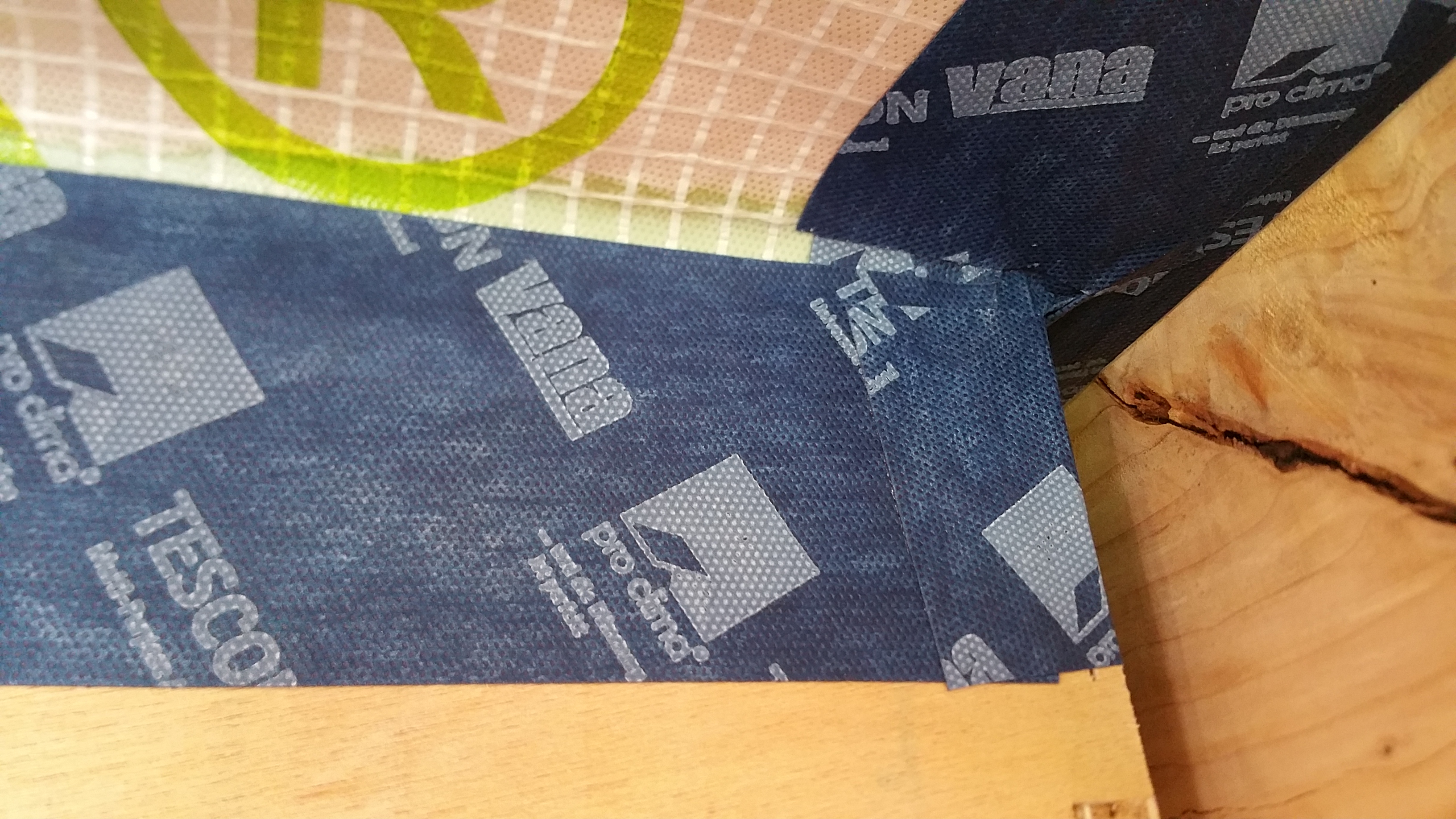
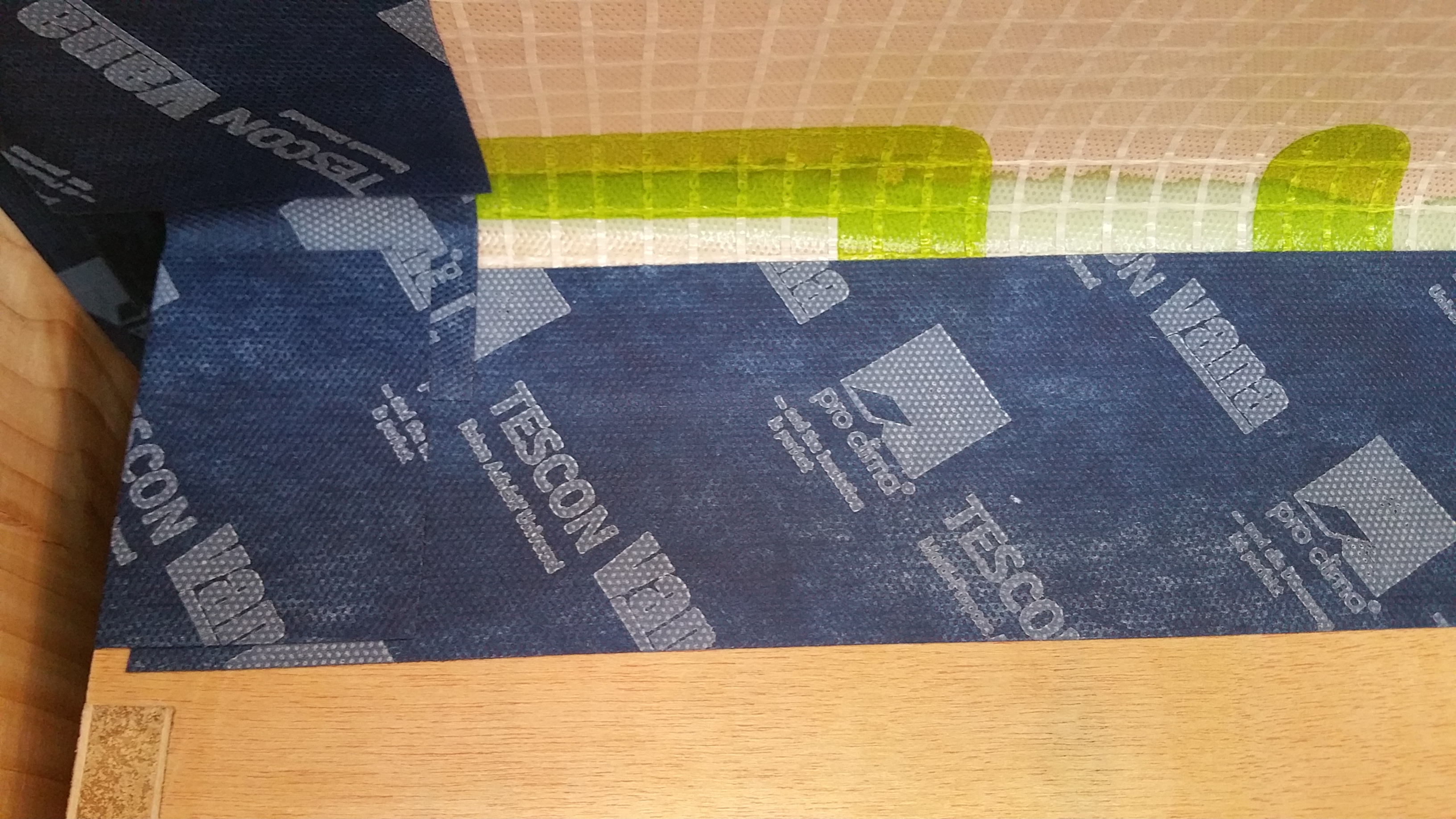
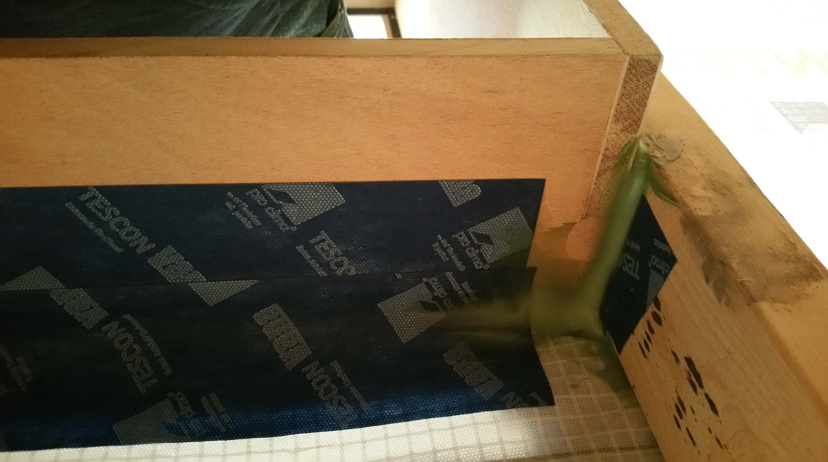
Because of this video, I sealed all of my corners for the windows and doors like this:
Adding Pro Clima HF Sealant after completing taping of the corner, just for added insurance against potential air leakage.
I also added some HF Sealant to the lower portion of the windows, since some air leakage showed up in this area with Anthony where components of the window itself come together in a seam.
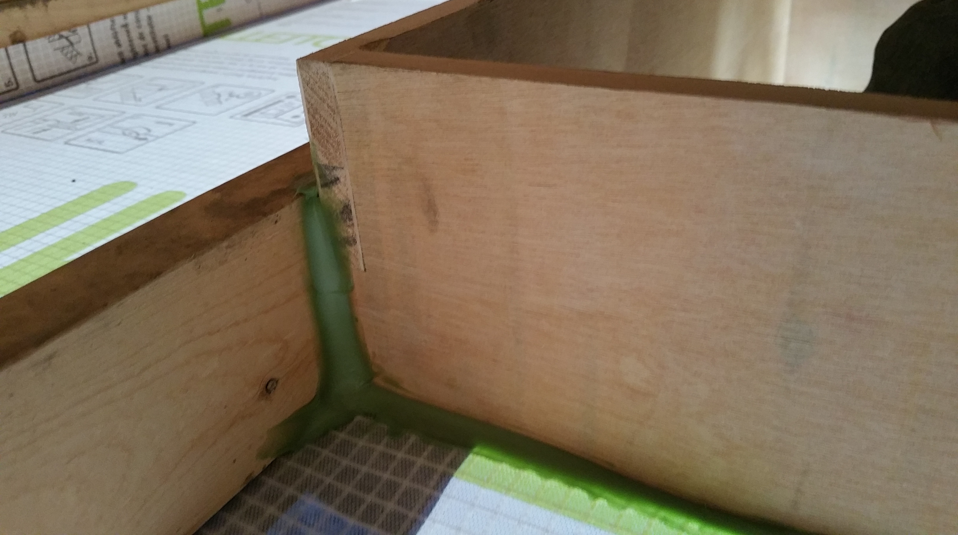
Seam near bottom of window where components meet — sealed with HF Sealant.
The areas where components come together often need special attention.
Close-up of this same area — seam in components sealed, along with the bottom corner of the window and the gap between window buck and window.
Even with layers of redundancy in place, in the picture below there was a small air leak still present at the bottom plate – sub flooring connection. A coating of HF Sealant easily blocked it.
Once the stud bays were insulated (after most of the siding was up), the interior walls would eventually be covered with Intello (I’ll cover the details in a future post on interior insulation), adding yet another layer of redundancy for mitigating potential air intrusion.
Area of kitchen sill plate leakage.
Anthony didn’t have any previous experience with a Passive House build, so it occurred to me that it might be beneficial to reach out to Floris from 475 High Performance Building Supply (he had already done our WUFI analysis for us), and Mike Conners from Kenwood Property Development to see if there was someone locally who did. Mike is a Passive House builder in Chicago who had already helped me out with some Rockwool insulation when we came up short earlier in our project (the two GC’s we fired repeatedly struggled with basic math), and he was very nice to take the time to answer some other technical questions for me as well.
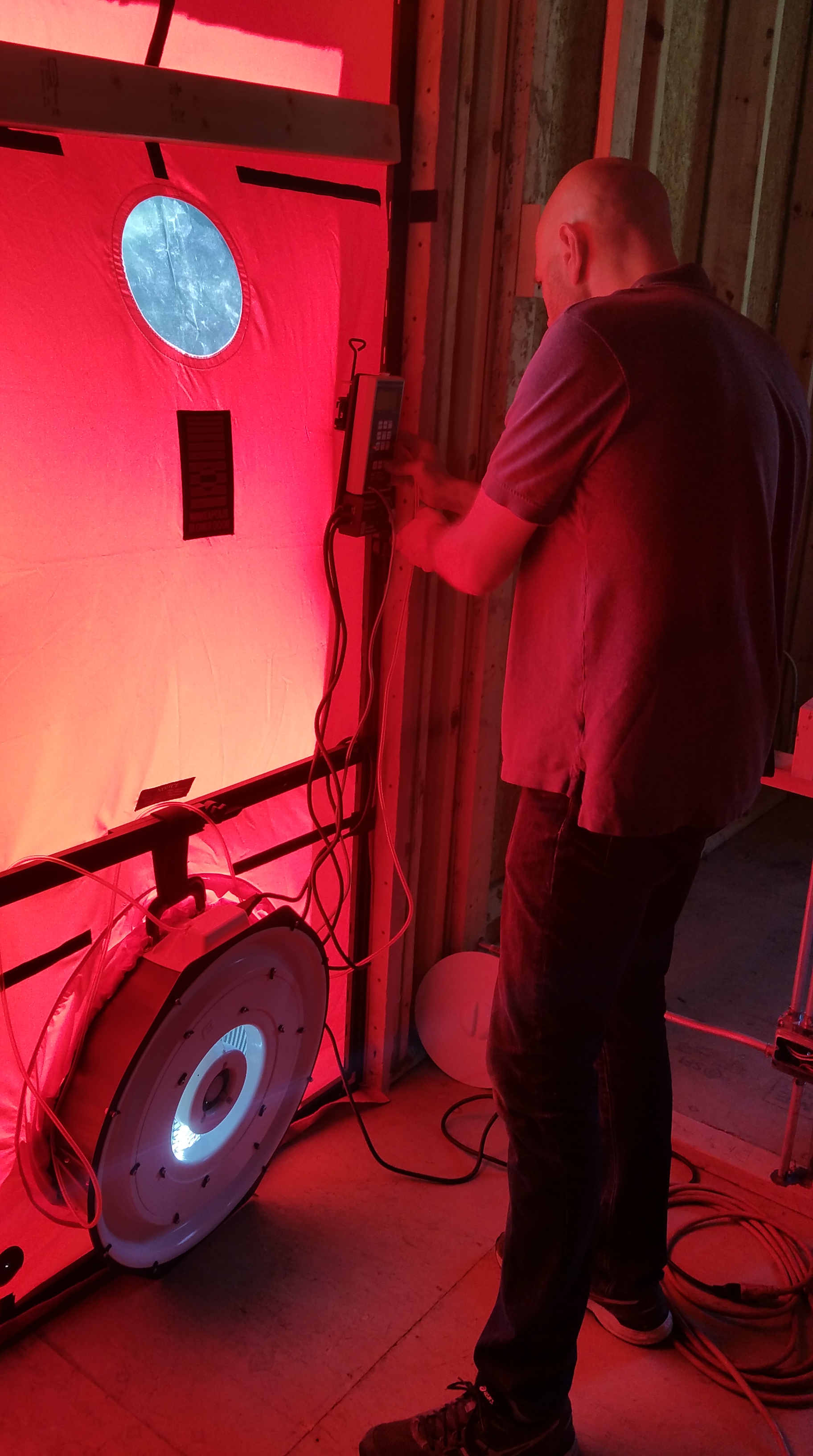
Steve would eventually make three trips to the house, doing an initial blower door test after the structure was weather-tight and all the necessary penetrations had been made through our air barrier, a second test after exterior continuous insulation was installed, and a final test after drywall was up to ensure there hadn’t been any increase in air leakage during the final stages of construction.
Steve setting up the blower door for his first test.
Following Passive House principles for our build, we also followed the same protocols for the blower door tests: Blower Door Protocol
With the structure under pressure from the blower door fan, Steve and I walked around the house while he used a small smoke machine in order to try and find any leaks that I could then seal up.
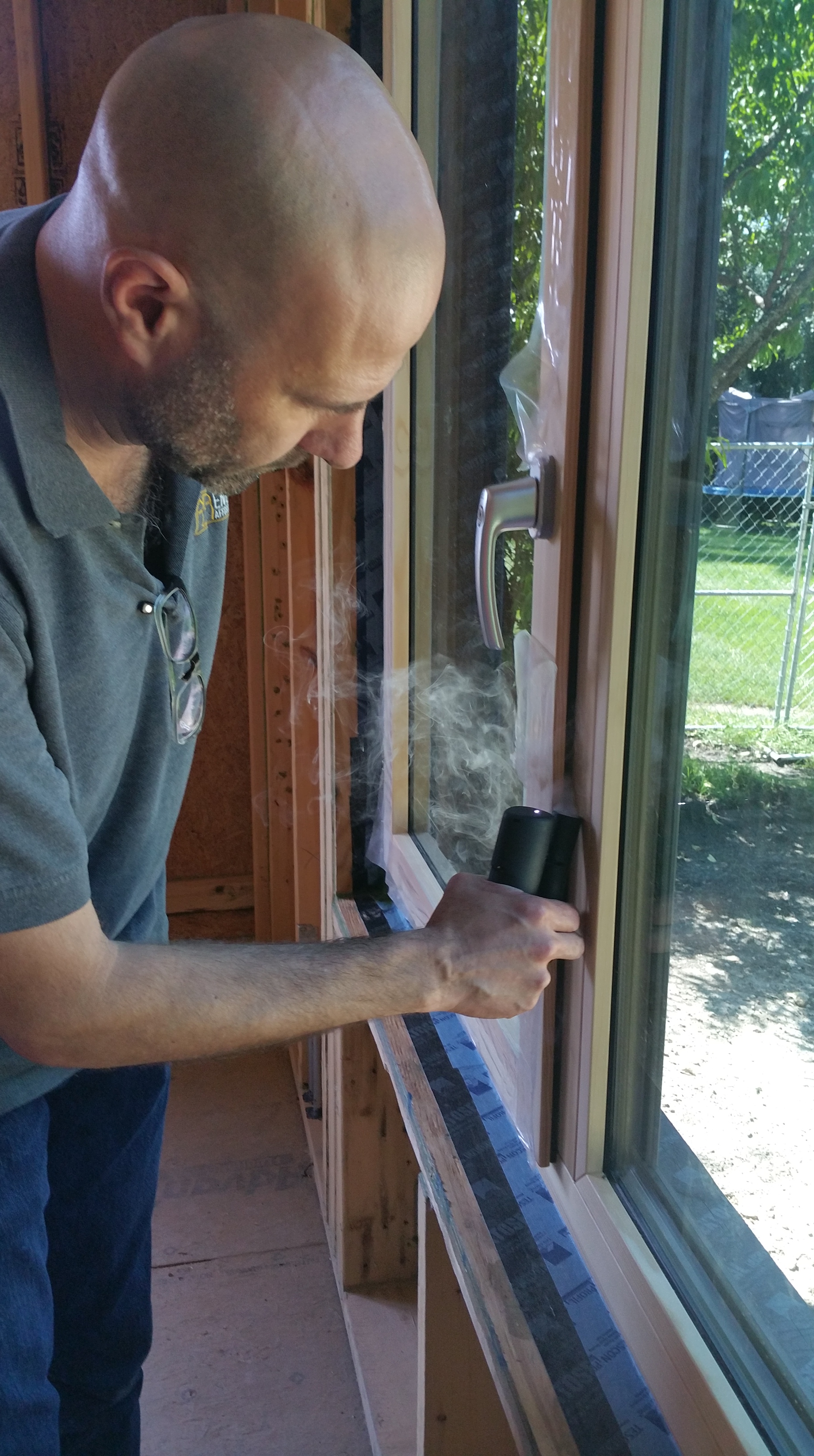
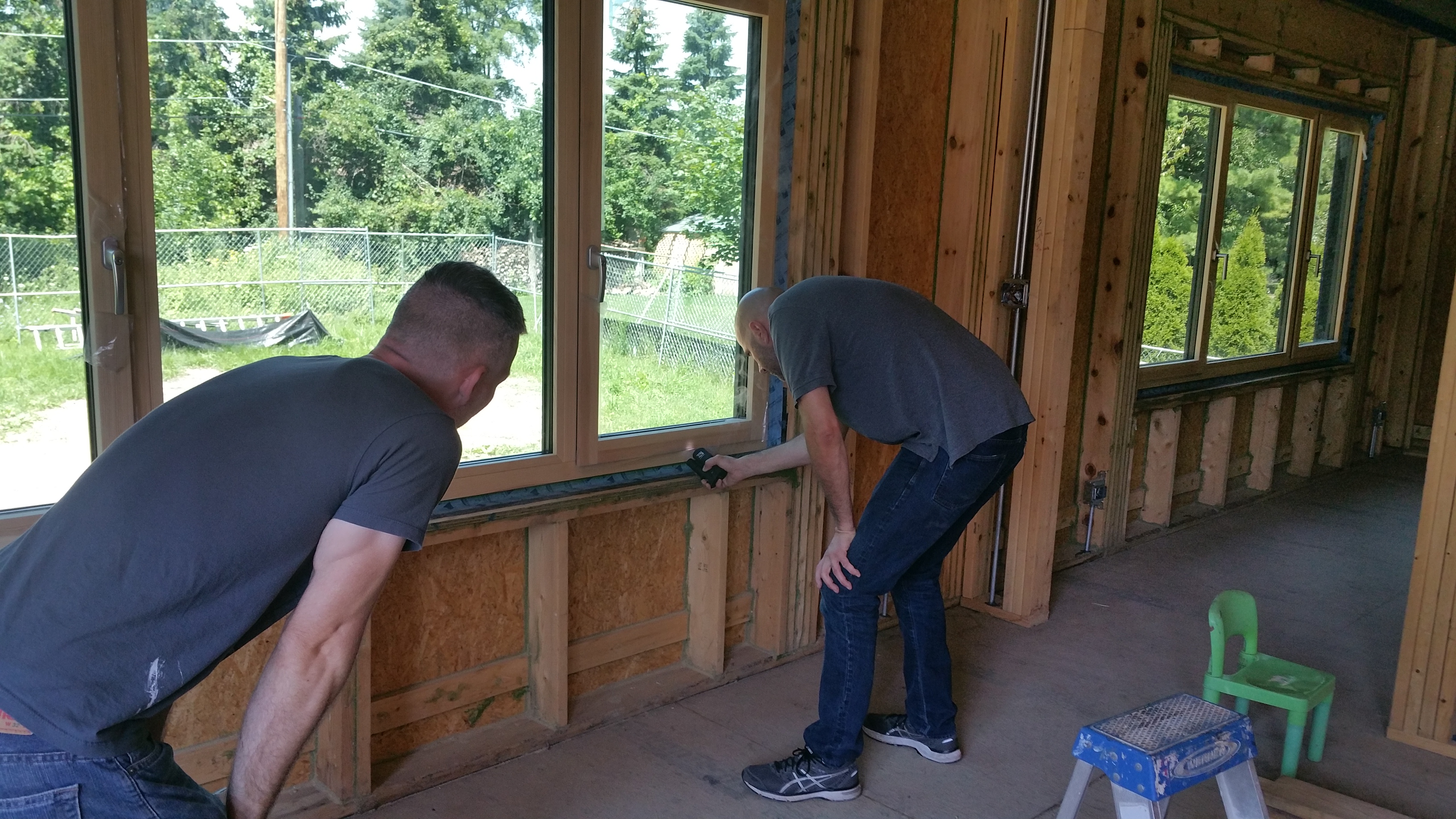
Steve starting at the windows. Here testing a window gasket for air leakage.
The gaskets around our windows and doors proved to be some of the weakest areas in the house although, comparatively speaking, it was inconsequential since the overall air tightness of the structure was fairly robust (favorite word of architects).
Steve showing me the impact a window in the unlocked position can have on air tightness. The gasket, ordinarily squeezed in the locked position, works to bring the sash and the frame tightly together.
Looking for areas around the windows that might need adjusting or additional air sealing.
For instance, even though no substantial air leakage showed up around this kitchen door, during our first winter this same door eventually had ice form outside at the upper corner by the hinges, on the exposed surface of the gasket where the door meets the frame.
After figuring out how to adjust the door hinges, there was no longer any ice showing up this winter, not even during our Polar Vortex event in late January.
Much the same thing occurred around our front door as well, with the same solution — adjusting the hinges to get a tighter fit at the gasket between the door and the frame.
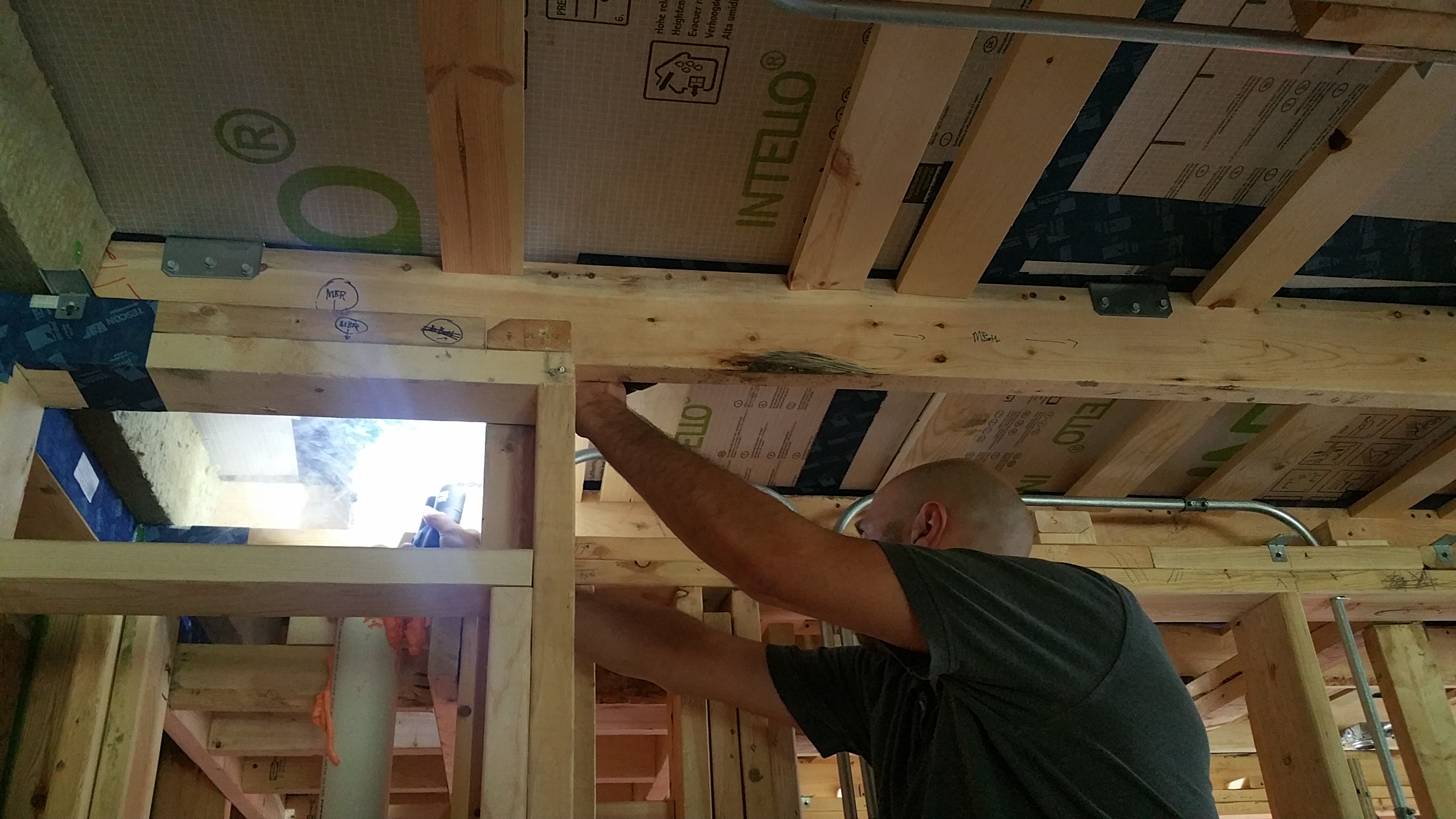
Steve testing the attic hatch for any air leakage.
Steve was nice enough to go around and methodically check all the penetrations in the structure.
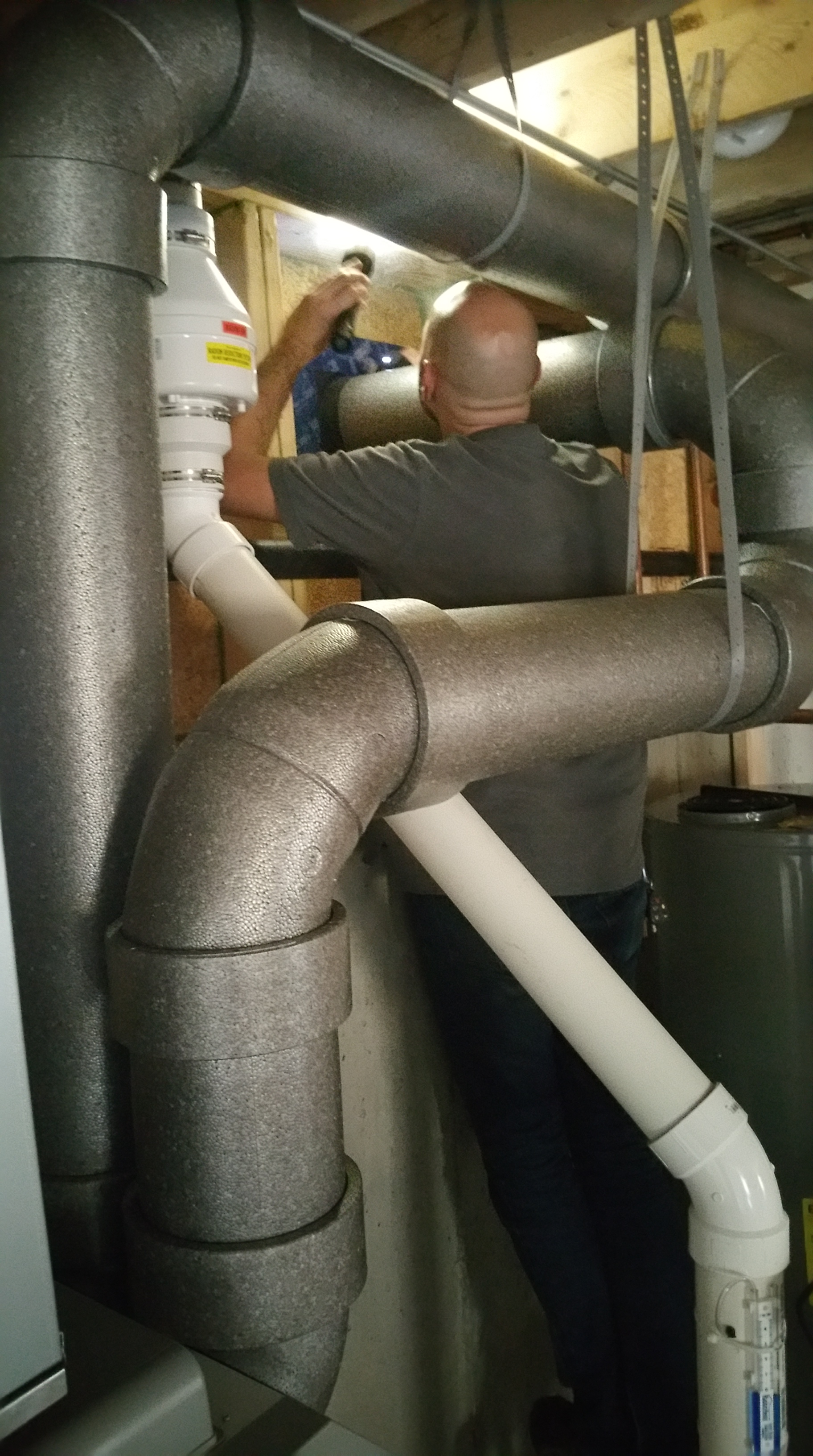
Steve testing for air leaks around the kitchen plumbing vent and some conduit.
Steve testing for air leaks around the radon stack.
Close-up of radon stack during smoke test.
There was one area in the guest bathroom where the Intello ended up getting slightly wrinkled in a corner during installation. With Tescon Vana and some HF Sealant I was able to address it so nothing, thankfully, showed up during the smoke test.
Steve testing area of Intello that I inadvertently wrinkled during its installation.
After looking around on the main floor, Steve moved down into the basement.
Checking for leaks at the main electrical panel.
Checking for leaks at the conduit as it exits the structure.
Looking for air leakage around the sump pit lid.
The lids for the sump pit and the ejector pit were eventually sealed with duct seal putty and some Prosoco Air Dam.
Testing the ejector pit for air movement.
Checking for air leakage around one of the Zehnder ComfoPipes as it exits the structure.
Looking for air leaks around the heat pump refrigerant lines as they exit the structure.
Checking around the penetration for our sump pump discharge to the outside.
Before the second blower door test, I was able to add some duct seal putty to the lids of the sump and ejector pits.
Ejector pit lid with some duct seal putty.
Below is a copy of Steve’s blower door test results, showing the information you can expect to receive with such a report:
For the last two tests Steve used a smaller duct blaster fan in order to try and get a more precise reading for air leakage.
With Steve just after the initial blower door test was complete.
Steve would be back two more times — once before drywall, and once after drywall — just to ensure we had no loss of air tightness develop in the interim stages of the build (especially after continuous exterior insulation with furring strips were installed).
Here are the final figures noting where we ended up:
We are well below Passive House requirements (both PHI and PHIUS), so there was a great sense of relief knowing that all the time and effort put into air sealing had paid off, giving us the tight shell we were looking for. Even so, it was still pretty exciting news, especially for a first build.
And here’s an interesting article by 475 HPBS regarding the debate over how air tightness is calculated for PHI vs. PHIUS projects, and the potential ramifications:
Our attic is designed mainly to hold our blown-in insulation (a future post will go over the details), as opposed to a place for running HVAC equipment, conduit for electric, or as a potential area for carving out additional storage space.
Nevertheless, in order to have access to our attic for future maintenance or repairs, I installed a well-insulated attic hatch in our master bedroom closet ceiling.
Following Passive House and Pretty Good House principles required trying to protect the thermal envelope, even in this relatively small area, in order to avoid what can be a notorious point of air leakage and heat loss (i.e., the stack effect).
There were two main products I considered using for this:
They also have a product that allows for a built-in ladder for easier access to the attic (you won’t need to drag your ladder in from the garage) while also maintaining a high R-value:
We ended up going with the Battic product, which I purchased through the Home Depot website (this saved me a trip to the store since it was delivered to site).
Some other products that I’m aware of include:
475 High Performance Building Supply used to sell a Passive House certified version with a fold-down ladder included, but I don’t currently see it listed on their website:
Because the Energy Guardian hatch is made out of rigid foam, I thought the Battic door was the better choice since it seemed like it would be a little sturdier and more durable. To be honest, once the product arrived and I unpacked it, I realized it was something I, or anyone with basic carpentry skills, could put together themselves (assuming you have the time).
Following the directions, I cut an X in the Intello on the ceiling between two roof trusses (and our 2×6 service core below each truss) in order to establish the opening for the Battic frame.
I folded the cut edges of Intello up into the attic for the two long sides of the Battic frame. For the two shorter sides of the Battic frame it was easier for air sealing to push the Intello down into the living area.
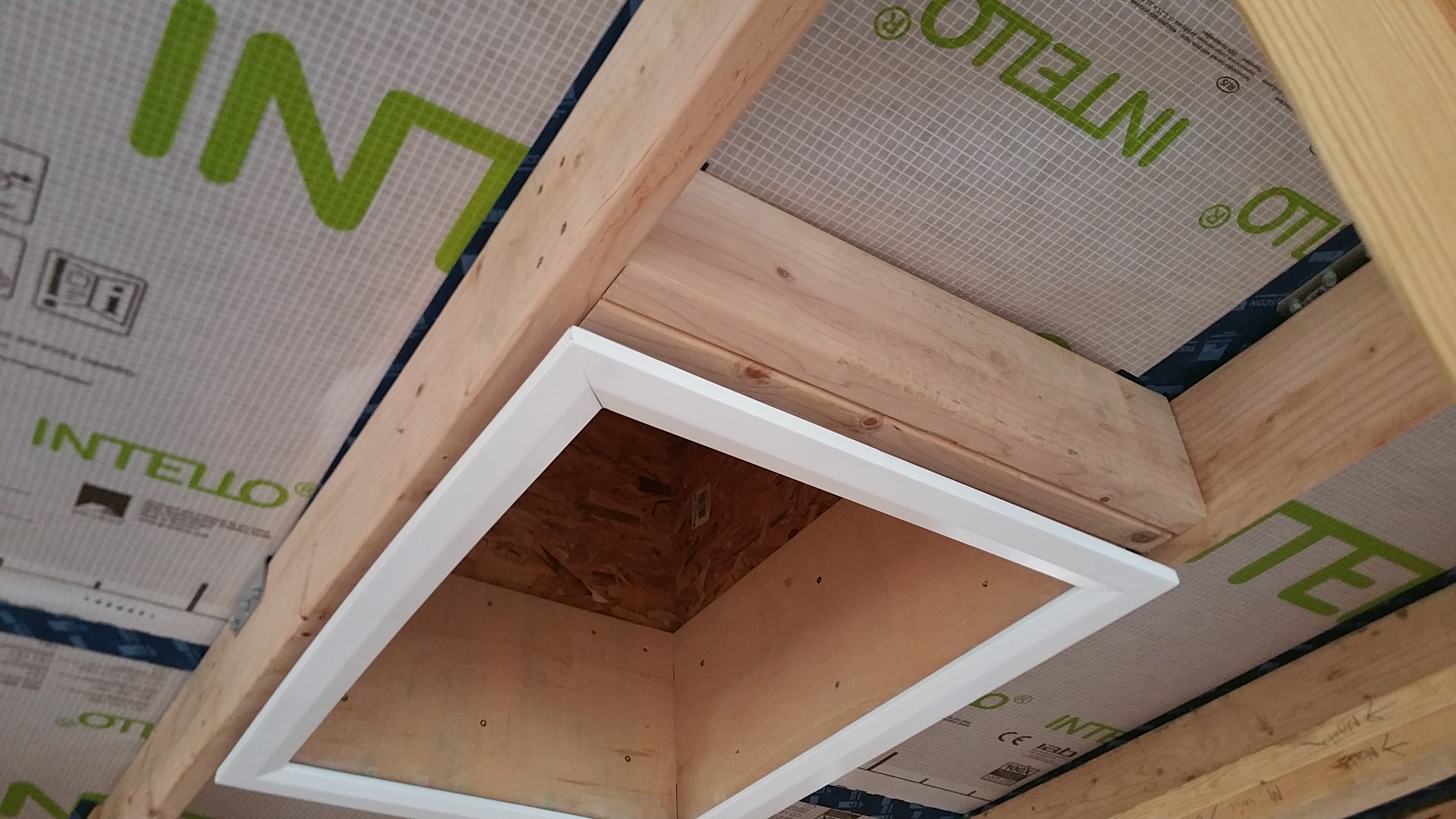
At this point I was able to screw the Battic frame into place.
Battic frame initially installed between roof trusses and 2×6 service core.
Air sealing the Intello to the Battic frame (short side between trusses).
Another view of the Intello sealed to the Battic frame.
View of the installed Battic frame from the attic.
Air sealing the connections between the Intello, the Battic frame, and the roof trusses in the attic.
Using HF Sealant to make the connections as air tight as possible.
Once the outside perimeter of the Battic frame had been air sealed to the Intello, the only place left for air infiltration was where the lid would meet the frame of the Battic hatch once it was installed (more on this later when I discuss my first blower door test).
There was some additional framing required, but it was just a couple of “headers” between the roof trusses to add structural integrity to the two shorter sides of the Battic frame.
Battic frame with additional 2×6’s on one of the short sides.
Since we were using a significant amount of blown-in insulation in the attic, it made it necessary to build up the sides of the Battic frame in the attic with some plywood to get the top of the opening above where the insulation would eventually stop.
Here’s another view of the 3 sides of plywood installed:
The fourth and final side of plywood was installed just prior to blowing in the insulation — in the interim this made getting in and out of the attic much easier.
After a couple of practice attempts, it quickly became apparent that raising and removing the lid once in place, and fighting to get it back down into the master bedroom closet, wasn’t worth the trouble. Instead, I built a small bench in the attic next to the Battic frame so I could push the lid up above the level of blown-in insulation, this way it could have somewhere to safely sit while dealing with any issue in the attic.
Battic lid resting on the bench.
It’s very easy to grab the lid off the bench and bring it back down into position while slowly walking down the ladder in the master bedroom closet to make the final connection/seal.
Although the installation process was fairly straightforward and headache free for the Battic product, if I had it to do over, I think I would have the attic access point on the exterior of the structure, for example, on the gable end of the house in the backyard.
Putting the access point above the air barrier would make meticulously air sealing the entry point for the attic less important, so keeping water out of the attic would be the main goal. An additional plywood buck would’ve been necessary, replicating what I did for our windows and doors (more on this later), but I think it still would’ve been the better option overall.
Putting the attic access on the exterior of the house would also mean avoiding an ugly hole somewhere in our drywalled ceiling. No matter how nicely trimmed out, these attic access points on the interior of a home never look right to me. We’ve tried to hide ours as much as possible by sticking it in our master bedroom closet, which has worked out well, but not having one at all on the interior of the house would make for a cleaner, better solution in my opinion.
If granted a do-over, I would also add a cat walk in the attic through the roof trusses. This would make getting to any point in the attic much easier to navigate. It would also help to avoid disturbing the blown-in insulation too much.
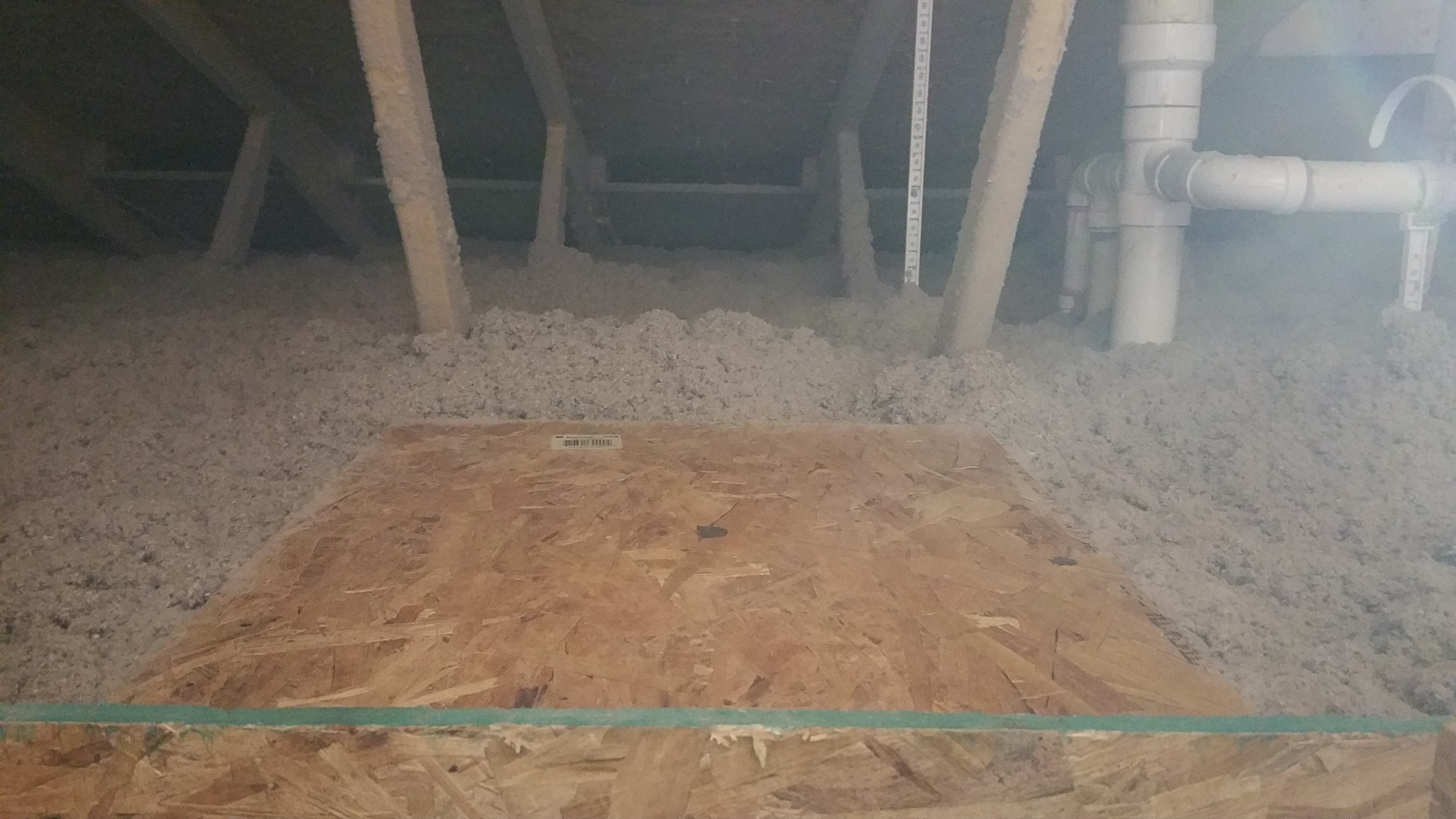
And here’s a photo of the bench in the attic, next to the opening for the Battic attic hatch, after the blown-in insulation was installed:
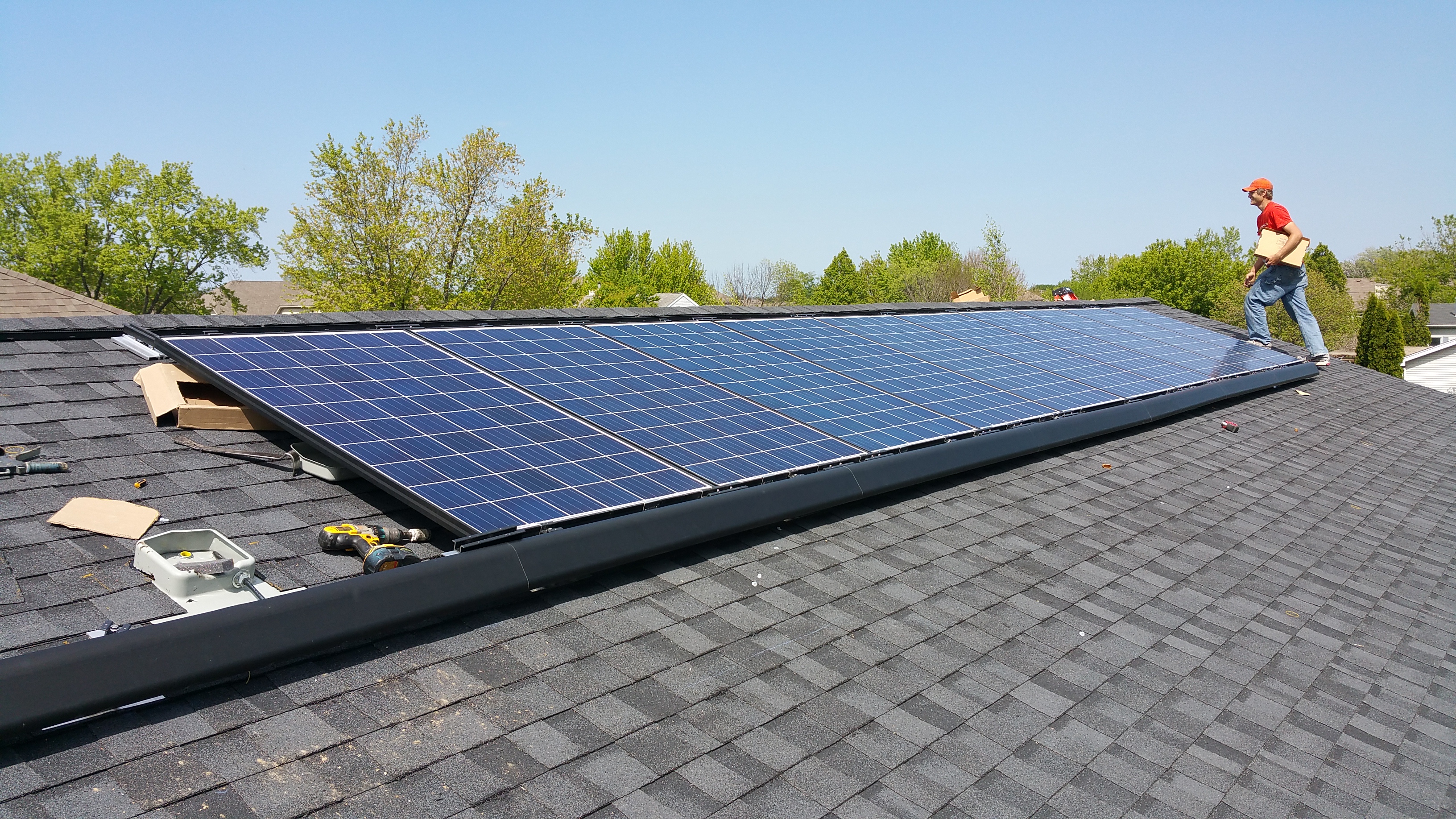
After deciding to pursue a combination of Passive House and The Pretty Good Houseconcepts, which entail careful planning and attention to air sealing, along with a significant amount of insulation, we knew we could have a shot at Net Zero, or Zero Net Energy (ZNE) — meaning we could potentially produce as much energy as we use by utilizing solar panels on the roof.
To find an installer in our area, we utilized the website Energy Sage. In addition to useful articles and information about solar, they also work with installers who can provide consumers with competitive bids. It didn’t happen overnight, but in about a week or two, we ended up with 3-4 bids before deciding to go with Rethink Electric.
The guys from Rethink staging the panels on the garage roof.
The System
Based on the suggestions from Energy Sage and Rethink, we ended up going with the following system:
2.915 kW DC System
4,059 kWh of system production
11 Canadian Solar panels
265W Module Enphase M250 (Microinverter)
Also includes web-based monitoring of the system’s production
In theory, this system could produce more energy than we use (it’s just my wife, my daughter, and myself who will be living in the house), particularly if we stick to all LED lighting, use Energy Star rated appliances, the heat pump water heater works as advertised, and we’re careful about avoiding using electricity when it’s unnecessary (e.g. turning off lights after leaving a room, or trying to address phantom loads).
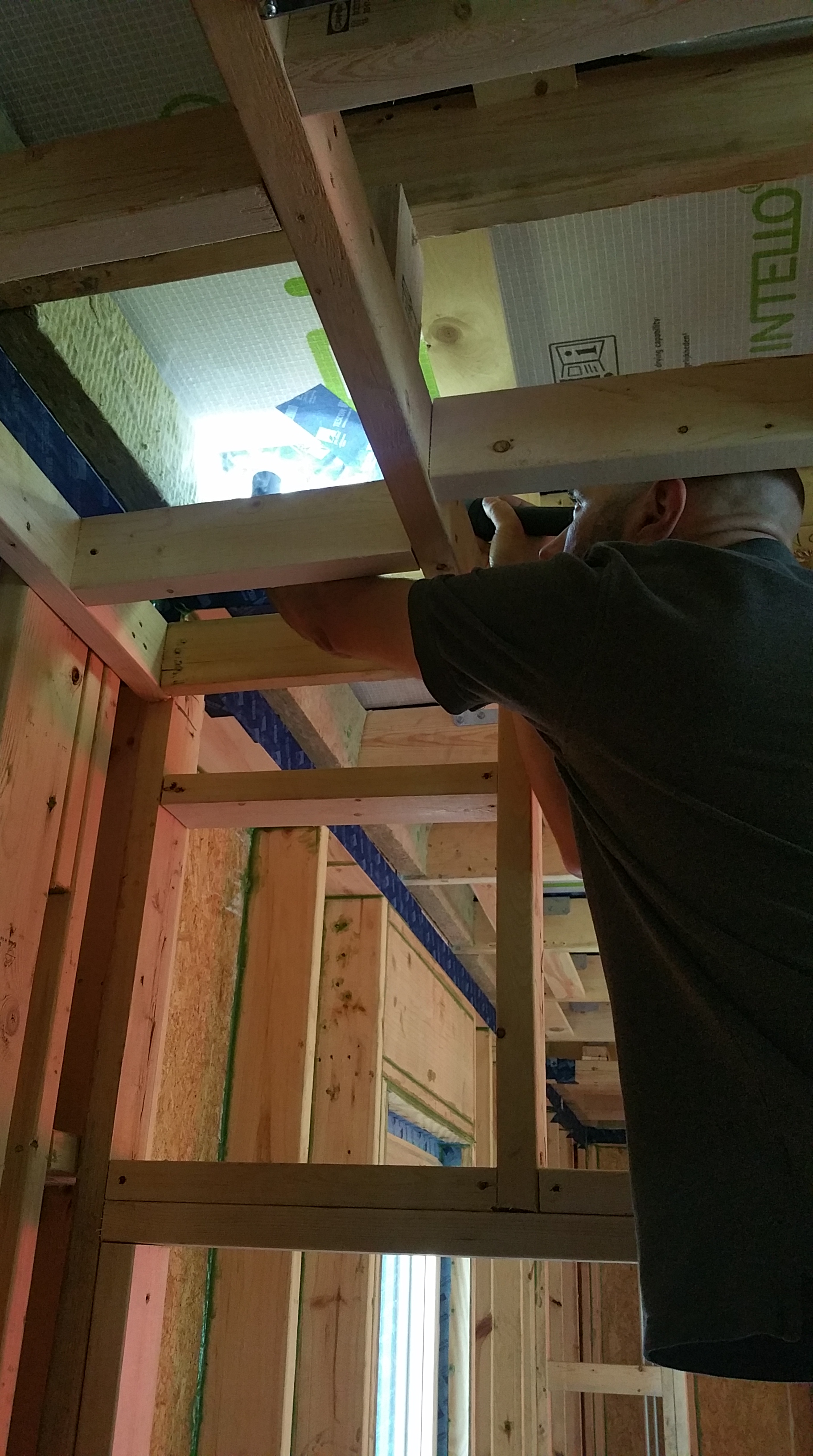
Anthony, from Rethink, air sealing the penetration through the Intello, our ceiling air barrier, with a Tescon Vana – Roflex gasket before sending his 3/4″ conduit into the attic.
Based on other projects I’ve read about, even homes initially built to the ZNE standard sometimes fail, in terms of overall performance, based on actual occupant behavior, so only time will really tell what impact our solar array will have on our utility bills. It looks like worst case scenario would be needing to add 4-6 more panels to get to ZNE or even carbon positive.
Anthony’s conduit entering the attic, sealed with a gasket from below.
Installation by Rethink went really well, and they were happy to work with me on properly air sealing the conduit that runs from the basement at the main panel before going up into the attic, where it eventually terminates on the roof when connected to the panels.
3/4″ conduit sealed for a second time on the attic side of the Intello.
The guys setting up the racking system for the panels.
Close-up of the base that’s holding the solar panels.
Anthony, Dan, and Cherif completing the install on the roof of the house.
The low profile racking system has a very sleek look.
Marking another big leap in the progress of the build:
The view of our 11 solar panels from our neighbor’s driveway.
Another view of the solar panels installed on the roof.
It was only after the installation that I realized what’s wrong with the following picture:
My screw up.
I was so worried about getting the air sealing details right on the interior, from the main floor to the attic, I completely forgot to let Anthony know about extending out his disconnect box 6″ to what will be our finished surface (once two layers of Roxul and two layers of 1×4 furring strips, along with cedar siding are installed). The day after they installed, I came walking around the corner of the house, saw this, and literally slapped my forehead (while spitting out a few choice expletives), as I realized my screw up.
Thankfully, Anthony was able to come back out and make the necessary adjustment:
The Cost
Here’s the cost breakdown on our system (if trends continue, a similar system should be less expensive in the future):
$12,519.50 Initial Investment
$(-3,755.85) Federal Tax Credit (ITC) 30%
$8,763.65 Net Cost of First Year
$(-3,816.00) Solar Renewable Energy Credits(SREC’s)
$4,947.65 Net Cost After All Incentives
It will be interesting to follow the performance of the solar panels over the course of a calendar year or two, just to find out exactly how well they perform. I’ll come back here and post monthly utility statements, noting output of the panels and our use, to give people a better sense of actual performance — hopefully this will help others in the planning stages of their own project to decide if solar (and how much of it) is right for them.
{January, 2021 Update: For actual energy demand and costs, please check out this post: Our Energy Bills}
In a conventionally built home, mudsills are typically an area of significant air leakage (if you’ve ever seen sill sealer — a thin layer of foam normally used to address this lumber-concrete connection — under an actual mudsill, you can visibly see just how poorly it performs).
In contrast, after reading about various strategies employed to reach the Passive House standard of 0.6 ACH@50 for air tightness, I decided to use the approach developed by architect Steve Baczek specifically for mudsills. There is an excellent article in Fine Homebuilding magazine that describes the details, and there is a companion series of videos available on Green Building Advisor(after the first video, membership is required, but it’s well worth it for this series of videos, as well as all the other information available on GBA).
We didn’t use the layer of poly, or the termite shield, but the remaining details we followed fairly closely. And we did make one product substitution — instead of using the Tremco acoustical sealant, we decided to go with the Contega HF sealant (less messy, lower VOC’s, and skins over and firms up enough to apply the Pro Clima tapes, all while remaining permanently flexible like the Tremco product — these products are available at foursevenfive.com).
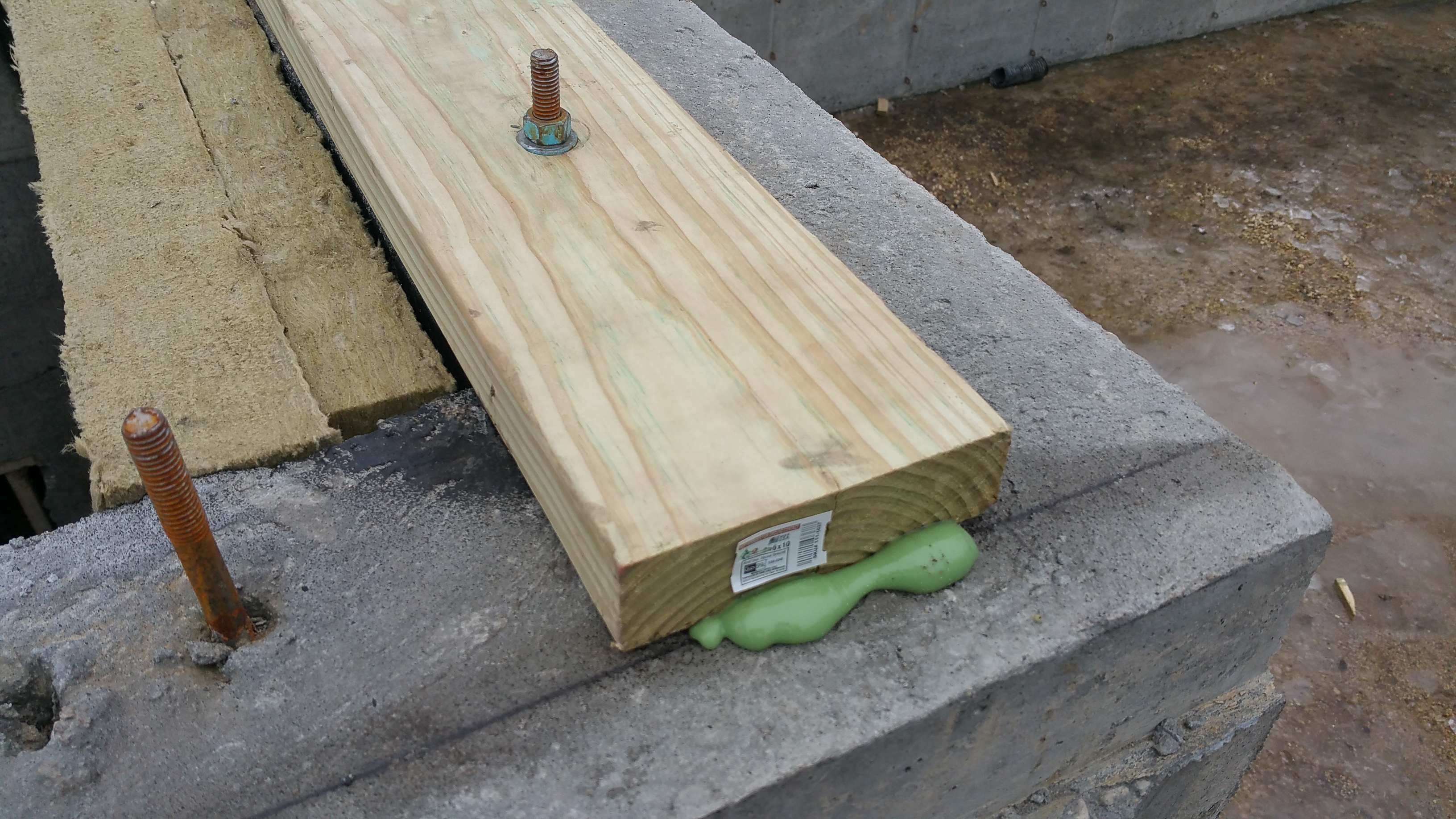
Billy and Phil setting up chalk lines for the mudsills.
Nils applying a thick, continuous bead of Contega HF sealant, including around the bolts, before the 2×6 pressure treated sill plate gets installed with a BG65 gasket underneath.
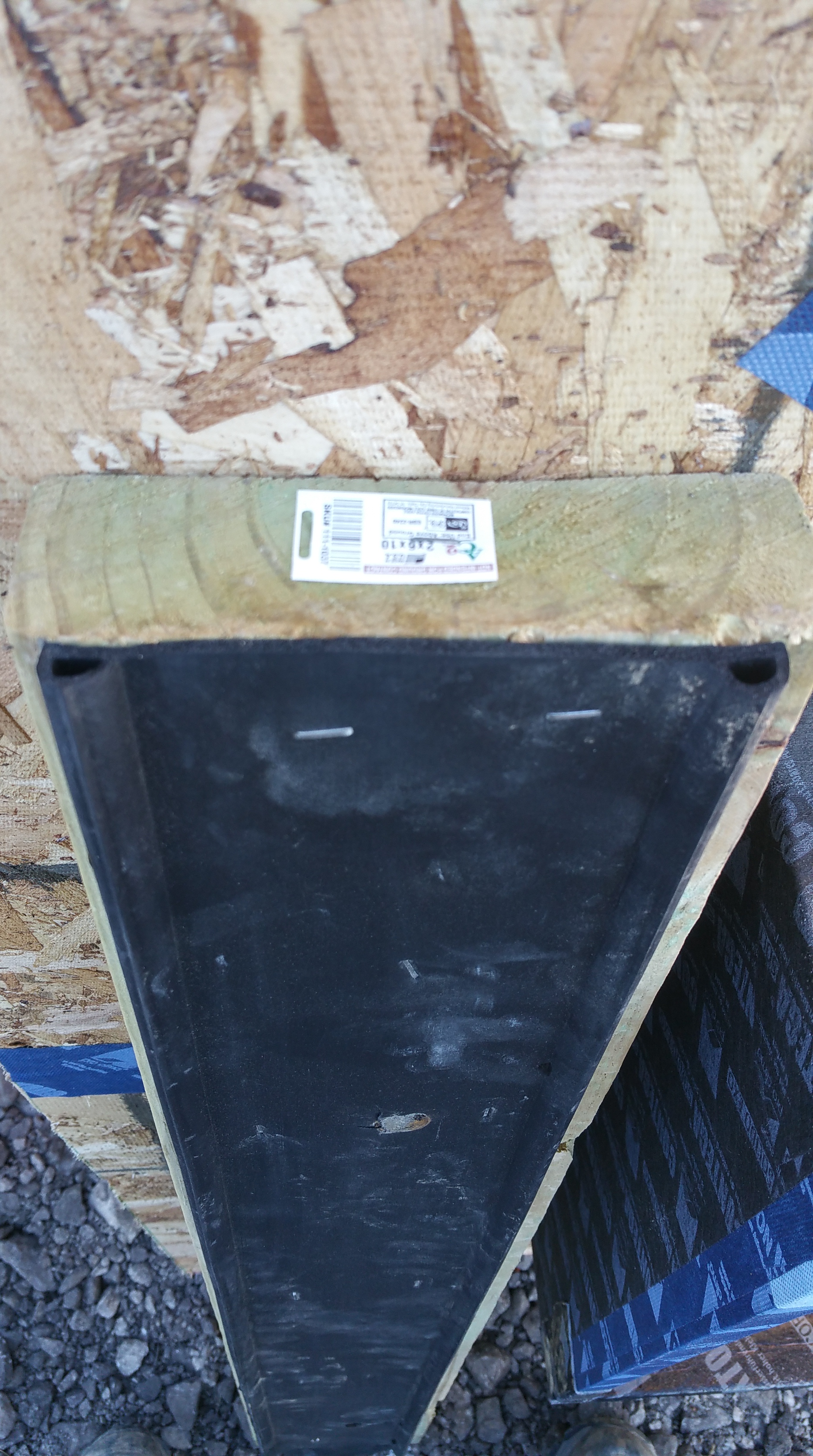
BG65 gasket from Conservation Technology stapled to the bottom of a scrap piece of sill plate.
BG65 gasket rolled up in the box it shipped in.
Sammy and Billy stapling the BG65 gasket to the sill plates before installation.
Mudsill installed with some squeeze out of the sealant.
Installing the sealant on the mudsill (interior/exterior edges, seams, and bolts/nuts/washers) required some gymnastics:
In theory, she’s helping me.
Mudsill after installation: sealant covering sill plate – BG65 gasket – concrete connection, with seams filled.
Once again, based on Steve Baczek’s design — going from exterior to interior — here is our Mudsill Air Sealing Approach:
Bead of sealant on the exterior side of the 2×6/foundation connection
BG65 gasket under the sill plate — along with a thick bead of sealant under the gasket and sill plate (including around bolts)
Bead of sealant on the interior side of the 2×6/foundation connection
And then, finally, a taped connection on the interior side of the 2×6/foundation connection as a last line of defense against air infiltration (which I’ll complete once all the trades go through the interior of the house).
The approach assumes I will make mistakes at certain points with each layer of air sealing, so I’m counting on these layers of redundancy to protect me from myself. Again, this is the first time I’ve ever done this, so the theory is that even if I make a mistake in one area, it’s unlikely that I will make a mistake in exactly the same spot with successive layers of air sealing.
Obviously I’m trying to do my best with each layer, but I like the idea of added layers of protection (a Passive House obsession), especially when accounting for the long-term life of the structure. Even if each layer could be installed perfectly, presumably each layer will fail eventually at different times and in different places (hopefully 50-100 years from now if the accelerated aging studies are accurate), so hopefully these layers of redundancy will help maintain significant air tightness far longer than if I chose to use fewer layers. Plus, I’m enjoying sealing everything up, so I don’t mind the process, which always helps.
For larger gaps (not just for mudsills, but anywhere in the building envelope), roughly 3/8″ inch or larger, I am utilizing backer rod to help fill the gap before applying sealant.
This is what it looks like:
The backer rod (readily available at any hardware store) makes life easier for caulks and sealants — less stress on the connection between materials as the inevitable expansion and contraction occurs in the gap.
Hammer and Hand’sBest Practices Manualhas the best explanation for their use that I’ve come across:
“While the humble sealant joint may be uncelebrated, it is vital to building durability and longevity. Proper installation is key to sealant joint integrity and function throughout a life of expansion and compression, wetting and drying, exposure, and temperature fluctuation.
Note: Because sealants are just as good at keeping moisture in as they are in keeping it out, placing a bead of caulk in the wrong location can result in moisture accumulation, mold and rot, envelope failure, and hundreds of thousands of dollars in repair and remediation. If we know anything, we know that building envelopes will get wet – the question is, “where will the water go?” Make sure you know the answer throughout construction, especially as you seal joints…
Diagram courtesy of Hammer and Hand’s Best Practices Manual.
… Joint Rule of Thumb: Sealant should be hourglass-shaped and width should be twice depth (shown in diagram). Backer rod diameter should be 25% larger than the joint to be filled. Joint size should be 4x the expected amount of movement (usually about 1/2” of space on all sides of the window casement). Ideal joints are within a range of 1/4” at minimum and 1/2” at maximum. Joints outside this range require special design and installation. Always use the right tool: sealant is not caulk and should never be tooled with a finger (saliva interferes with bond). Substrates need to be clean, dry, and properly prepared (primer if necessary). When dealing with thermally sensitive materials, apply sealant under average temperature conditions because joints expand and contract with changes in temperature…”
Example: Piece of backer rod being inserted into gap between header and 2×6.
It’s not visible, but the wood-concrete connection at the side wall has a piece of backer rod embedded between the two materials, making it easier for the sealant to bridge the gap over the long term.
Air Sealing: Rim Joist – Floor Joist – Mudsill Connections
Since there was time between completion of the rim joist/floor joist installation and the installation of the sub flooring (a weekend), I took the opportunity to seal up all the visible connections.
Billy and Johnny installing the floor joists.
Once the subfloor goes in, these connections are still accessible from inside the basement, but the space to work in would be really cramped and uncomfortable (at least I thought so).
Rim joist – floor joist – mudsill connections prior to sealant being applied.
The same areas after applying the sealant:
I found the silver Newborn sausage gun (photo below) worked great for thick beads under the mudsills, but the blue gun worked even better for all other seams. Because the blue gun utilizes disposable tips, it was easy to cut the tip to exactly the size I needed, thus using (wasting?) less material (and hopefully saving a little bit of money).
An added benefit of the disposable tips is less time required for clean up at the end of the day (always a good thing). Both guns work great, and appear to be really well-made, although I would probably only buy the silver one again if I consistently needed a fat bead of sealant.
Newborn sausage guns I found on Amazon. The blue one works great for thin beads, the silver for thicker beads (e.g., under mudsills).
In the photo below, I filled larger gaps with either backer rod, or in the case of the largest gap, bits of pulled apart Roxul Comfortboard 80, before applying the sealant. Since this is the first time I’ve done this, these are the kind of connections that I failed to anticipate beforehand. They are definitely worth planning for.
The temptation is to just fill these kinds of voids with sealant, but for the long-term durability of the connection backer rod or some kind of insulation stuffed into the gap is a better solution. Filling the voids before sealing doesn’t take much additional effort, so it’s definitely worth taking the time to do it right.
Knee Walls Installed
Because our lot is sloped, the plans called for a series of knee walls:
The guys installing the knee walls (left to right: Johnny, Nils, Sammy, and Billy).
When I saw the first piece of Zip about to be installed, I realized the bottom edge, which is exposed OSB, would be sitting directly on top of the Roxul on the foundation. While it’s unlikely that water will find its way to this edge (the flashing for the wall assembly will be installed over the exterior face of the Zip at the bottom of the wall), it seemed like a good idea to tape this edge with the Tescon Vana for added protection and peace of mind (even if it only protects this exposed edge until the rest of the wall assembly is installed).
First piece of 7/16″ Zip wall sheathing installed.
Knee wall pictured below had all exposed seams in the framing lumber filled with the Contega HF sealant before also applying the Tescon Vana tape, all of which was done prior to the Zip sheathing being installed. The sealant takes about 48 hours to cure enough before you can effectively cover it with the Pro Clima tapes (something to consider when setting up scheduling goals).
Knee wall being covered in Zip sheathing.
Close-up of knee wall with Zip sheathing and sealed seams.
For the bottom, exposed edge of the Zip sheathing, I cut the Tescon Vana tape like I was wrapping a present…
Taped bottom edge of Zip sheathing over face of mudsill.
Once the Zip sheathing was installed on the knee walls, I could move into the basement and seal up the connections between the Zip and the framing members, in addition to hitting any seams in the framing itself.
Once the house gets closed in, I will go back and tape the connection between the top of the foundation and the mudsill for one last layer of protection against air infiltration.
Knee wall with Zip sheathing after sealing up all the connections.
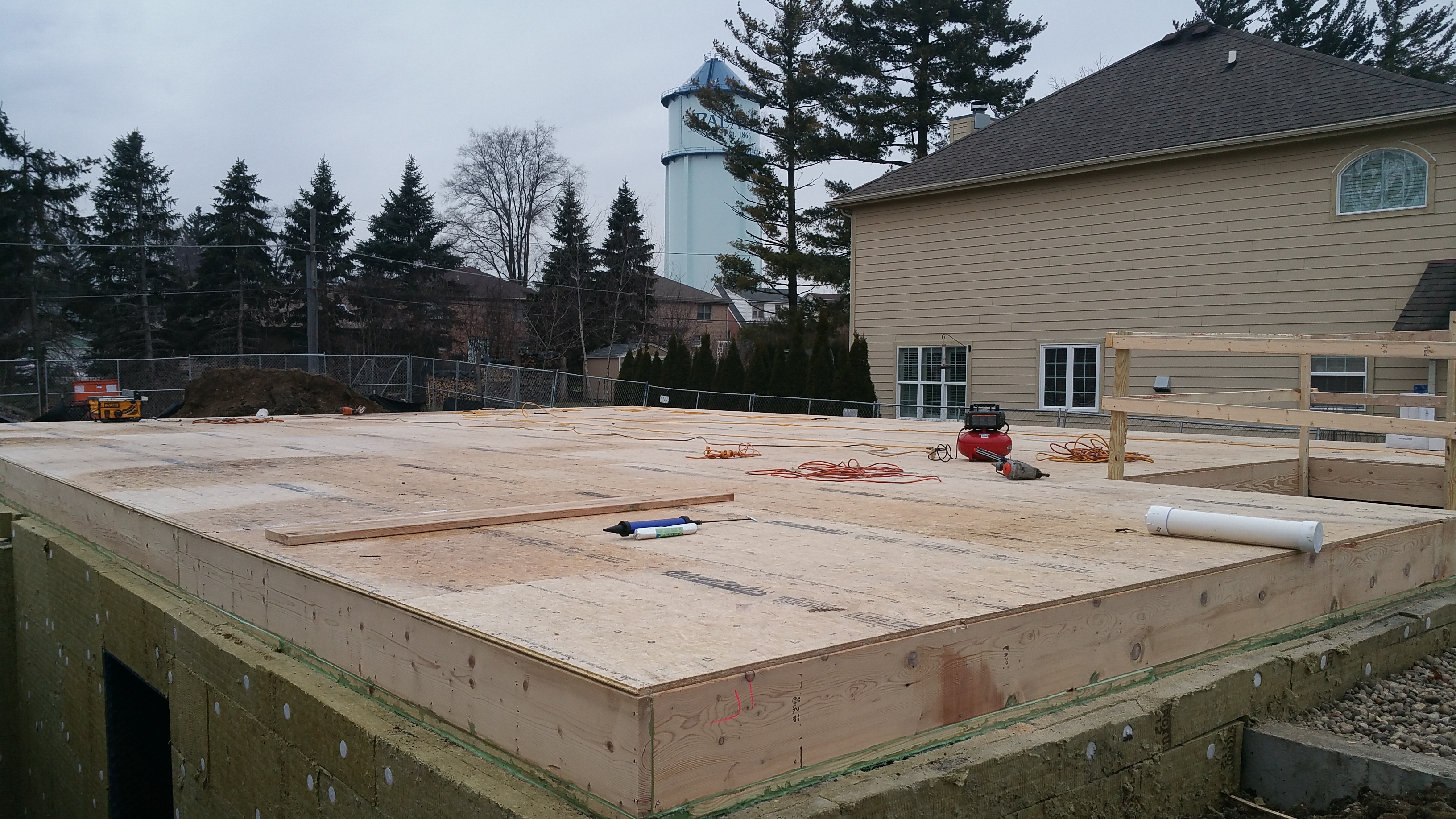
Subflooring
We decided to use Huber’s Advantech Subflooring after years of reading about it in Fine Homebuilding magazine, and based on the online comments from installers who see the added benefits that come with what is an admittedly higher price point. For instance, it’s more resistant to moisture, so it should produce more stable, flatter flooring (e.g. hardwood or tile) when the house is complete, in addition to preventing annoying floor squeaks.
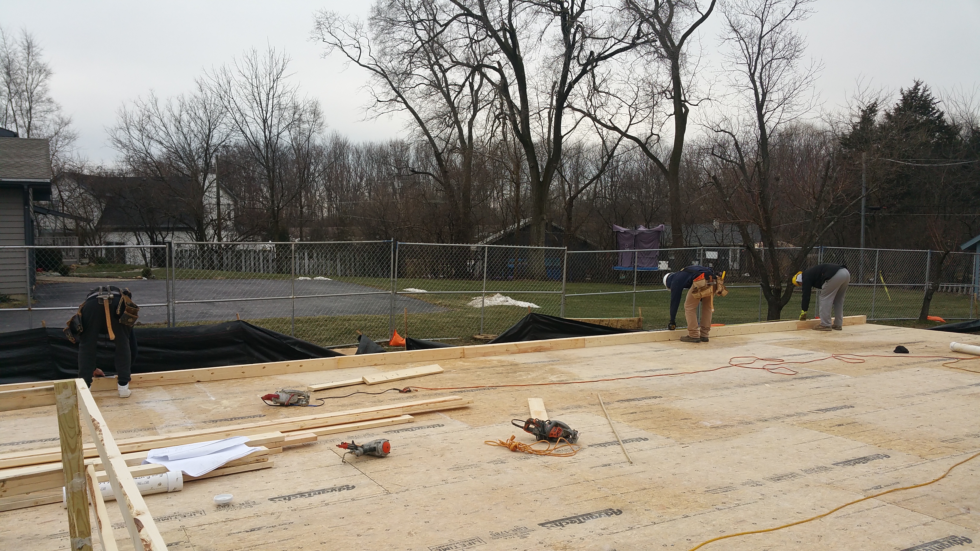
First sheets of subflooring being installed by Billy, Phil, and Nils.
In order to maintain a high level of indoor air quality (IAQ), we’ve been seeking outlow or no VOC products. So, in addition to the Advantech subflooring, which is formaldehyde-free, we chose the Liquid Nails brand of subfloor adhesive (LN-902/LNP-902) because it is Greenguard certified. Another great resource for anyone trying to build or maintain a “clean” structure is available at the InternationalLiving Future Institute website: The Red List
The product takes much longer to dry when it’s cold and wet outside — at least 2-3 days in our experience (sometimes even longer). It’s nice to see more “green” products showing up in the big box stores, rather than having to always special order them.
Standing by what will be the kitchen door. The subflooring was installed with nails and Liquid Nails subfloor adhesive.
Corner of our slowly growing wall assembly. The connection between the subflooring and the top of the rim joists was eventually sealed with the Contega HF sealant.
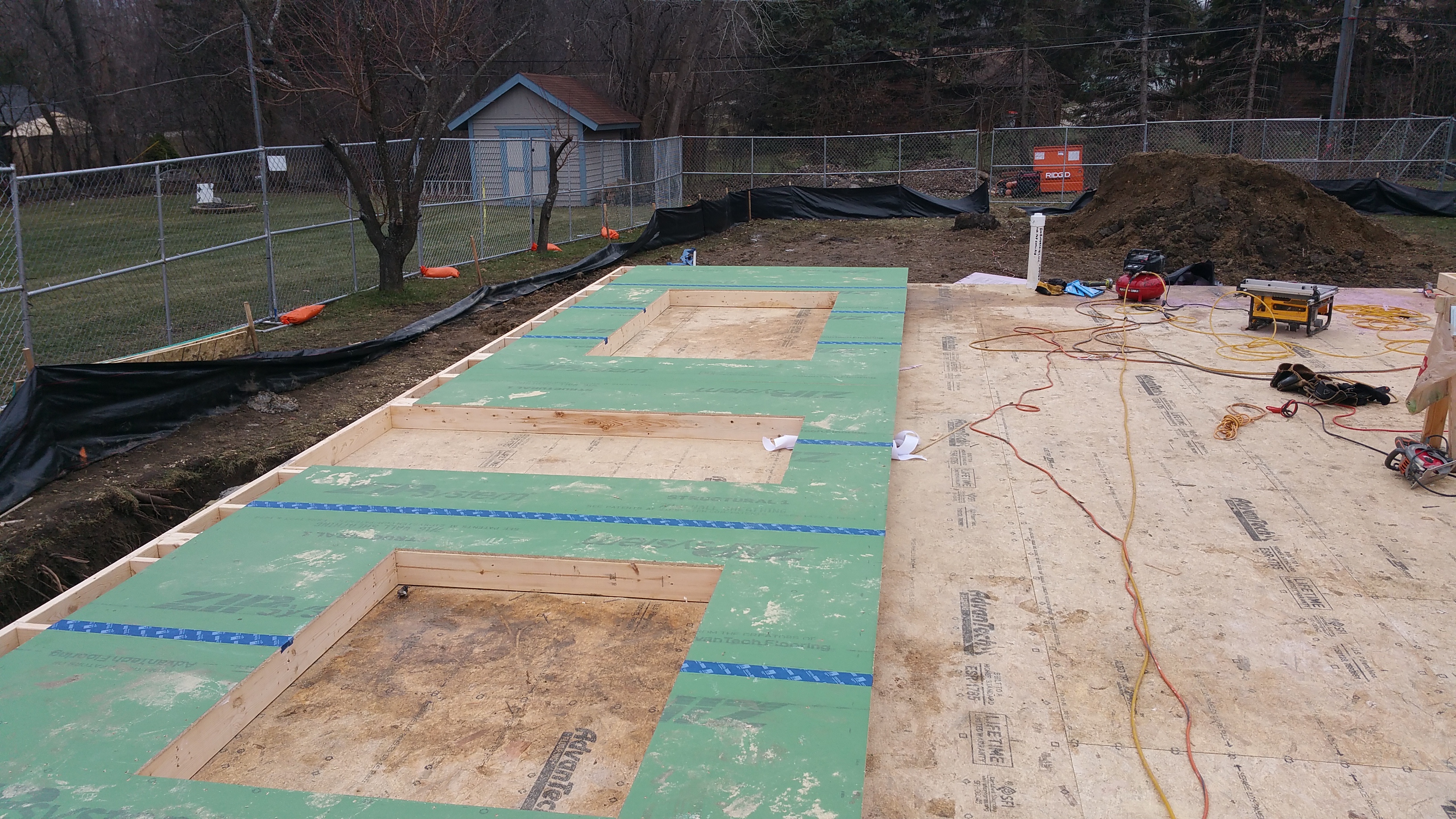
Basement slowly being covered by subflooring:
Walls Go Up
Our wall assembly is almost entirely based on Hammer and Hand’s Madrona House project, which I discuss here: Wall Assembly
Our blank canvas.
In preparation for construction, I built a mock wall assembly in order to easily explain to anyone on site how the various components should go together. It also gave me a chance to practice using the Contega HF sealant, along with the various Pro Clima tapes from 475 High Performance Building Supply.
It’s been exciting to see the walls go up, incorporating the many details in the mock wall assembly.
Men at work: Zach, Phil, and Sammy laying out the walls.
Zach and Phil installing the Zip sheathing over the framing.
Phil laying down a consistent and continuous bead of construction adhesive (trying to avoid a bead that runs back and forth between fat and thin), before the Zip sheathing is installed.
We were fighting the rain, ice, and mud, but I was able to get the Tescon Vana tape over some of the seams in the Zip sheathing before the walls went up.
Sammy and Billy help me apply the Contega HF sealant to each nail hole, and then make it lie flat with a swipe of the spatula, so the Tescon Vana tape that will be applied later will also lie flat.
Section of wall nailed, taped, and nail holes caulked — ready to be raised up.
The final step before the walls were raised was to staple the B75 gasket to the bottom of each sill plate.
First section of wall going up: Billy, Zach, and Sammy doing the heavy lifting.
Zach establishes plumb, while Phil readies to make the wall secure.
The guys continue with the south walls.
View from south-east corner of the house with the guys framing in the shadow of the water tower:
The only section of wall where the B75 gasket rolled up on itself is shown below — no doubt because this was the most difficult section to get into place because of the stair opening. Otherwise, the guys had no issues with the gasket.
Even on this wall where the gasket did roll up on itself, I will cut off the excess that ended up on the interior side before sealing the connection with the subflooring, and then spend some time filling the void on the exterior side with backer rod and sealant as well.
Zach is the only dedicated, full-time framing carpenter on the crew (the other guys do a variety of carpentry-related work). He has a production background, and it shows with the energy and ease with which he works. He clearly enjoys what he does for a living (In photo: Zach, Sammy, and Billy). Sammy and Billy may not realize it yet, but they’re learning a lot from him (even if he does razz them all day long).
Below you can see some of the junctions where different materials meet, and the effort that’s going into air sealing these inevitable gaps: sealant at rim joist corners, rim joist – subfloor connection, and gasket under the wall sill plate:
Wall is up.
Same corner as above, but now looking down the exterior side of the wall.
We’ve tried very hard to keep foam out of the wall assembly and the overall structure itself (based on environmental concerns), however, one place where it did find its way in was the insulated headers for above our windows and doors:
Billy and Sammy putting the insulated headers together.
End of the day. The fourth wall awaits.
First look at what will become our front facade.
Once the perimeter walls were up, I went around with an impact driver and decking screws to tighten the connection between the Zip and the framing members, especially at the top of the walls. Although the Liquid Nails adhesive helps a lot, it still makes for an imperfect connection between the sheathing and the framing members:
Looking down at the top plate. The visible gap is between the side of the top plate and the Zip sheathing. I was able to close gaps like this one at the top of the walls using decking screws. The decking screws also closed similar gaps around window and door rough openings. This should make sealing these areas easier, and the connection more durable.
Leaning over the top of the wall to install the decking screws.
Having seen construction adhesive and nails in action, I would recommend a glue-and-screw approach if you’re trying to fully maximize the tightness of the connection between the sheathing and the framing.
Nice view as I apply the sealant.
My wife giving our Zip sheathing blue chicken pox with the Tescon Vana tape in order to seal all the nail holes.
It’s difficult to see, but this tape is embedded inside a sheet of ice. It rained overnight, before turning to ice. We’re asking a lot of these tapes and sealants. This piece of tape looks like fingertips holding on for dear life.
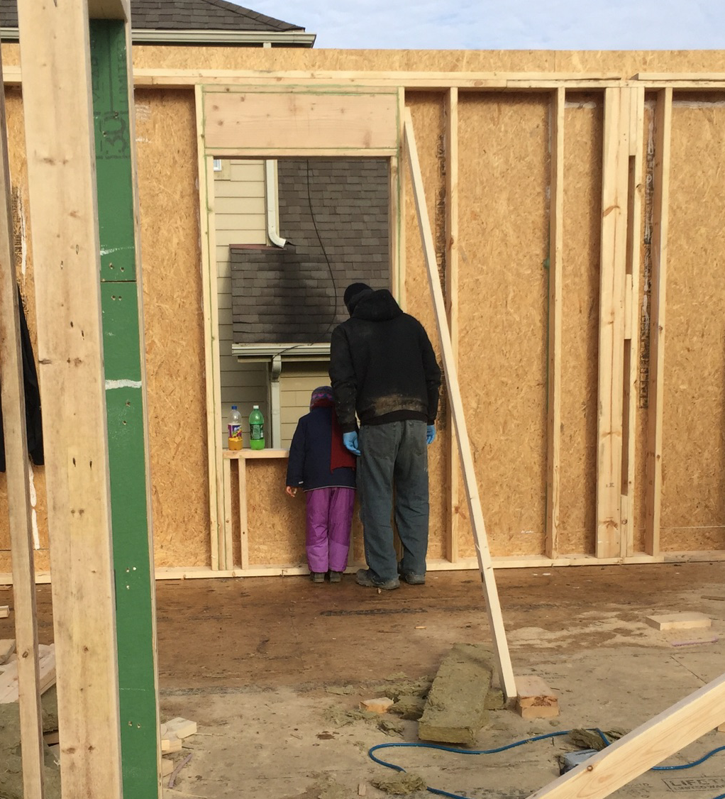
The Beast gets a first glimpse of the view from her bedroom window.
I was wondering why I would ever need more than one of these. Now I know — bent, scratched, and cracked, the Pressfix from475 HPBS did its job well.
In the summer my wife and I teach a class together, called Excel 2, which is one small component of a larger, overall Excel Program (my wife is a high school Social Studies teacher).
Typically, Excel students come from first-generation immigrant families. They are college-bound students who have exhibited great potential, but who are in need of some encouragement, particularly in regards to taking Advanced Placement (AP) courses (huffington post). For most of our students, they will be the first ones in their family to attend college, so it is understandably an intimidating prospect in any number of ways.
The course itself is three weeks in the summer session, its focus on developing reading and writing skills by utilizing non-fiction reading assignments. We emphasize the importance of correct spelling, proper grammar usage, and attention to detail by requiring multiple revisions to several thesis paragraphs, which are themselves based mostly on college-level reading assignments.
You can imagine how well this goes over with incoming high school sophomores and juniors — especially in summer. We’ve tried to overcome this dilemma (how to motivate young high school students to tackle a course based on rigor when many of their friends are out enjoying summer break) by delving into topics they are intimately familiar with, but hopefully in ways they have not yet confronted.
Some of our Excel students with my wife, Anita: (front row) Aubrey and Imani, (back row) Eduardo, Anita, Cecelia, and Karen.
As a whole, 50% of the students attending Palatine High School qualify for free and reduced lunch. Not surprisingly, then, the Excel students face some unique, if not daunting challenges, both in and out of the classroom. In addition to the normal stresses associated with being a teenager, many of them deal with balancing school work with long work hours at low-paying jobs (helping their families make ends meet), social pressures to stray down the wrong path (in any number of ways), and even (most heart-breaking of all) confronting what researchers term being food insecure — in plain English, not always knowing when or where they will get their next meal.
We present the class to the students as an opportunity to test themselves, to really see where they are, currently, in terms of a whole host of skills. The main goal of the Excel 2 program, therefore, is to really challenge their abilities, not just in terms of reading and writing skills, but also soft skills such as interpersonal communication, the importance of body language, time management, and self-discipline.
Essentially, we try to give them a college-level course experience, hoping it better prepares them for the eventual reality. In other words, we’d rather they struggle in high school with us than have it happen when away from home for the first time, off on their own, at college (atlantic)(newsweek)(washington post).
Here’s an example of our ever-changing syllabus: Excel 2 – 2015
As you can see from the reading assignments, we encourage our students to start asking questions about everyday things they may be taking for granted. We hope this sharpens critical thinking skills, but we also hope it encourages them to be more active participants in their lives, rather than just sleepwalking through their days as passive consumers.
Consequently, when it came time for us to find a new place to live, we saw it as a good opportunity to practice what we preach:
What exactly do you want from a new house?
If you’re going to buy a house (and you’re lucky enough to even contemplate doing so), what should it look like? A condo? A townhouse? Or a single-family residence?
In which neighborhood are you going to buy?
How many square feet do you want (or need)? How many bedrooms? Do you want (or need) a formal living room or dining room? Do you want (or need) a basement?
What architectural style appeals to you?
How are you going to furnish the interior?
Should you care about indoor air quality (IAQ)? And if you do, how do you protect it or improve it?
What do you want in your walls and attic for insulation? How much do you need?
How much will utilities cost? Are there cost-effective ways to reduce those costs?
Are renewables — solar, wind, or geothermal — worth considering? How long is the payback period?
Do you want your house to be environmentally friendly — and what does that mean anyway?
Instead of moving into the typical, leaky, not very environmentally friendly suburban condo, townhome, or house (we were leaving behind the latter), we thought it would be more interesting to see just how “green” we could make our next house.
Because we wanted a yard to do plenty of landscaping and gardening, we narrowed the choices down to a single-family house. And, instead of tackling the challenges that come with a retrofit, we decided to try building new.
Much like hearing Jonathan Ive talk about an Apple keyboard, we appreciated the detail required to meet the certified Passive House standard. At the time (summer 2014), this seemed like the way to go.
After the experience we had with our original builder(2015), and then subsequently trying to learn as much as possible about the Passive House standard, in addition to discovering the Pretty Good House concept along the way, our house plans have evolved into a kind of 3-headed hybrid: Passive House science+Pretty Good House+Net Zero (Zero Net Energy: ZNE).
The goal of all three: dramatically reduce the energy consumption of our house as much as possible (especially our dependence on the energy grid). We also want to do a significant amount of planting and growing in our yard, mostly xeric plants that require little additional watering, in order to combine house and yard into an eco-friendly system of sorts.
Our last home (approx. 2800 sq. ft.) was a fairly typical suburban tract house. It had builder-grade windows and doors (most of which had to be replaced after just a few years), very little insulation in the walls (the switch for the back porch light would actually ice up when temperatures fell below 20° F), and it had a great deal of under-utilized space (e.g. a two-story foyer, a formal living room and dining room, and a fourth bedroom, all of which saw little use).
With our new home (just over 1500 sq. ft. of living space), we’re trying to turn all of this on its head so we end up with something we really want and will enjoy. To paraphrase Kevin McCloud: ‘maybe it’s better to have a little bit of something special than a lot of something mediocre’.
An oft-quoted statistic (1)suggests a significant amount of our greenhouse gas emissions can be attributed to our structures (typically the figure is in the 40-50% range) — including residential, commercial, industrial, and governmental — so maybe change really does begin at home (SA)(greenbelt movement).
(1) According to a recent Fine Homebuilding article, “Better Than Average”, by Brian Pontolilo: “It’s not clear how much our homes contribute to greenhouse-gas emissions and to climate change. The most recent data available from the Department of Energy is from 2009-2010. Outdated as it is, this data indicates that residential buildings contribute around 20% of total U.S. greenhouse-gas emissions. This includes fossil fuels used on-site (e.g. natural gas for cooking and heating) as well as electricity.” (September, 2016 issue, p. 64)
The title of this blog entry was lifted from a lyric in this Talking Heads song:


")


You must be logged in to post a comment.