kimchi & kraut

Passive House + Net Zero Energy + Permaculture Yard

Tag Archives: chicago passive house

Our Energy Bills

4

The Logic Behind the Effort and Added Cost of Passive House

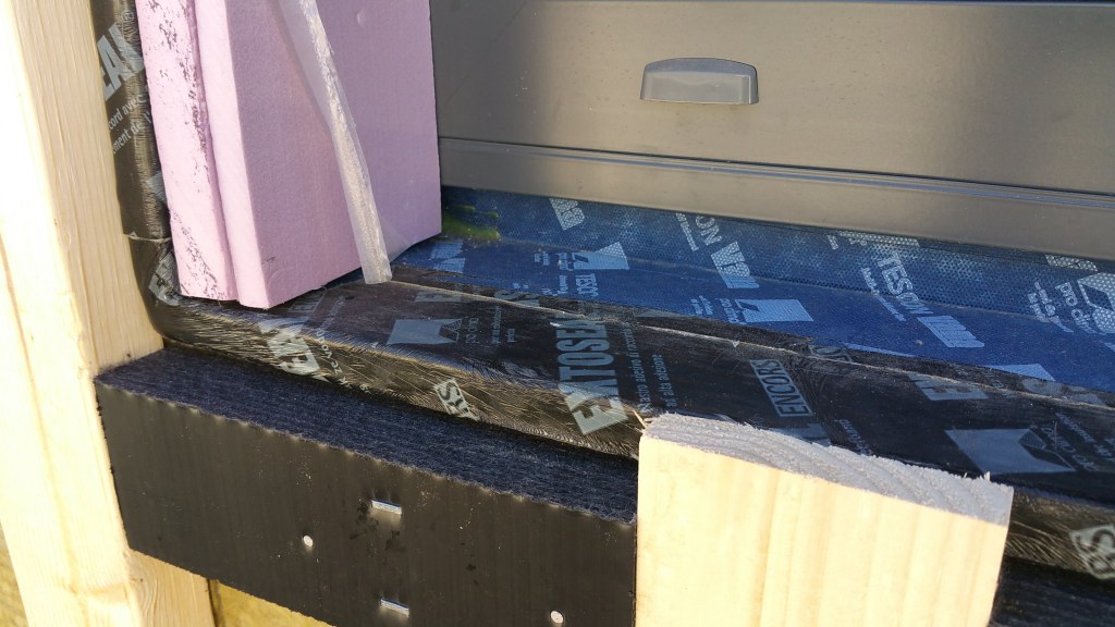
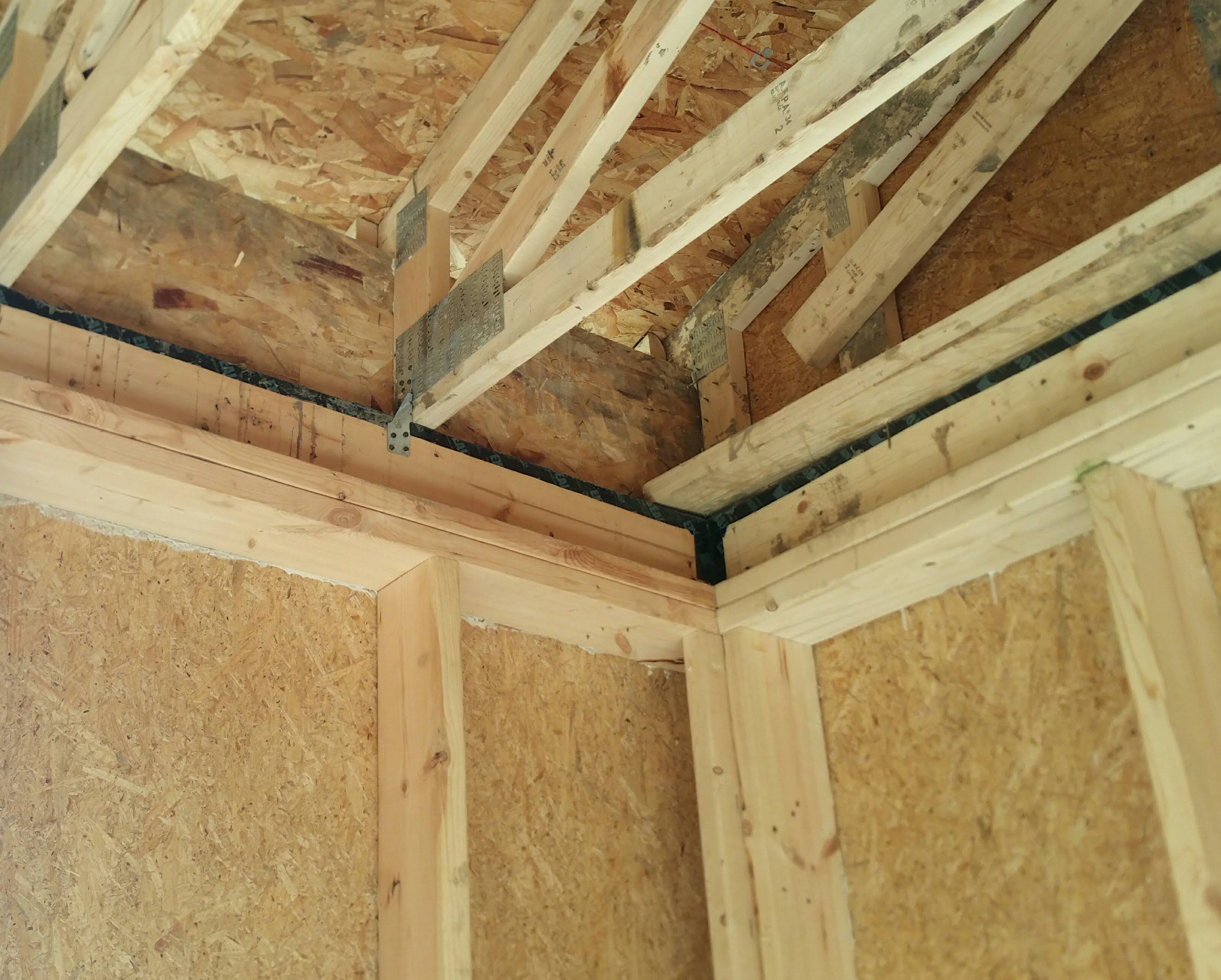
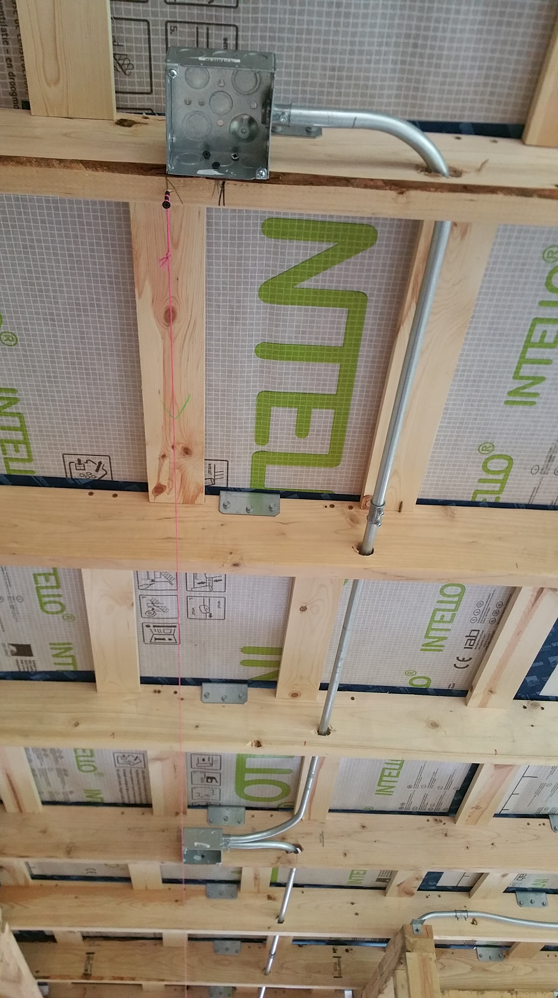
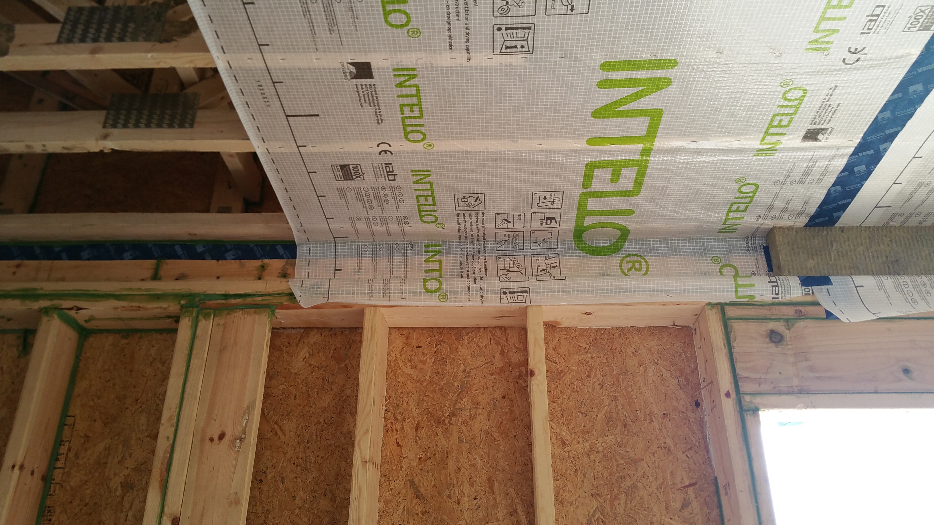
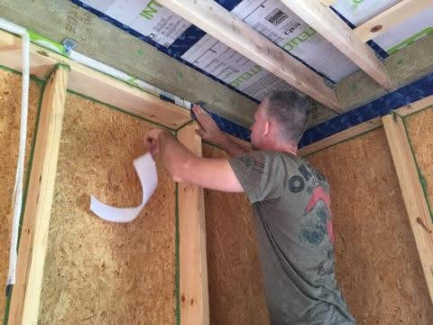
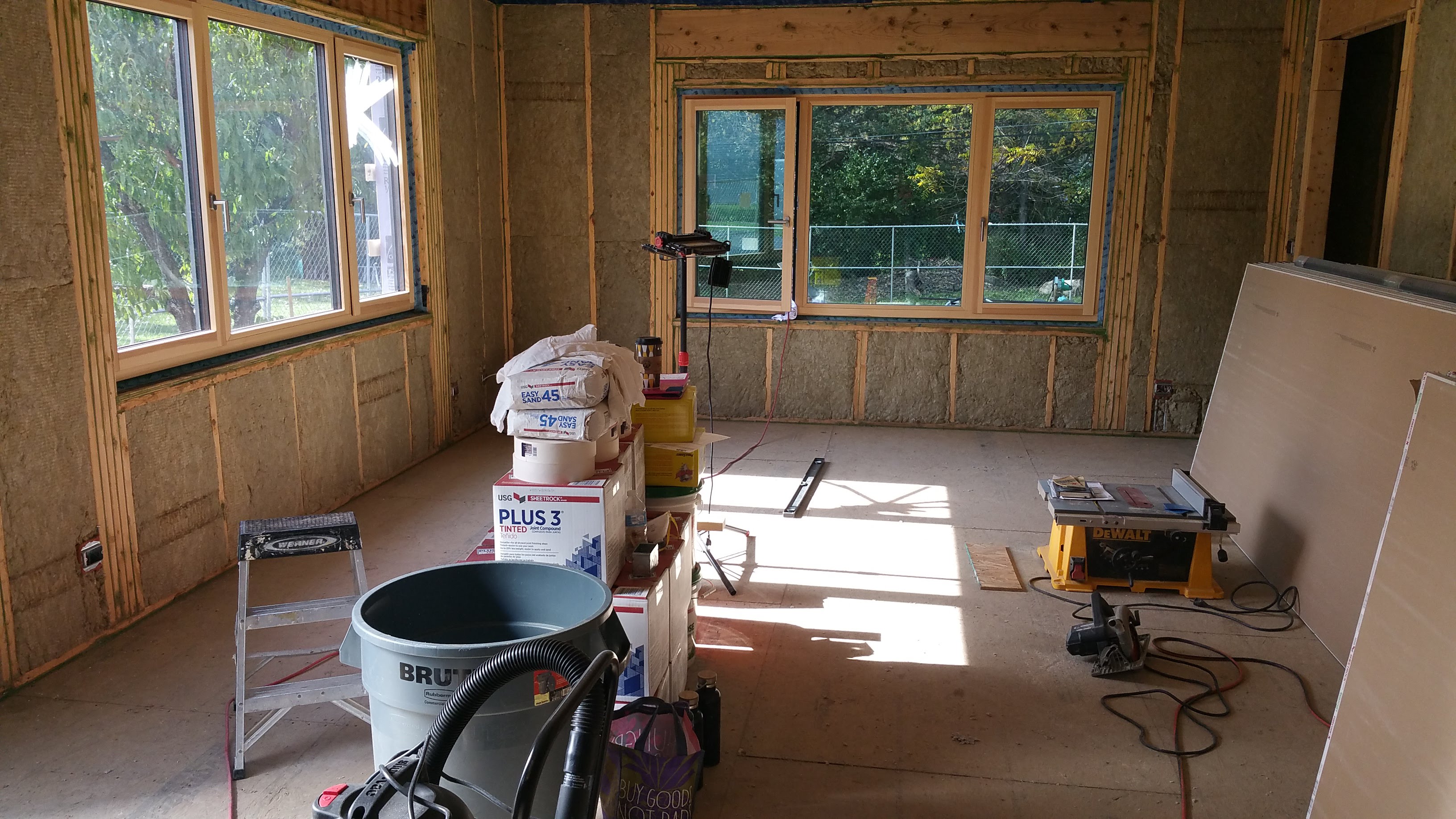
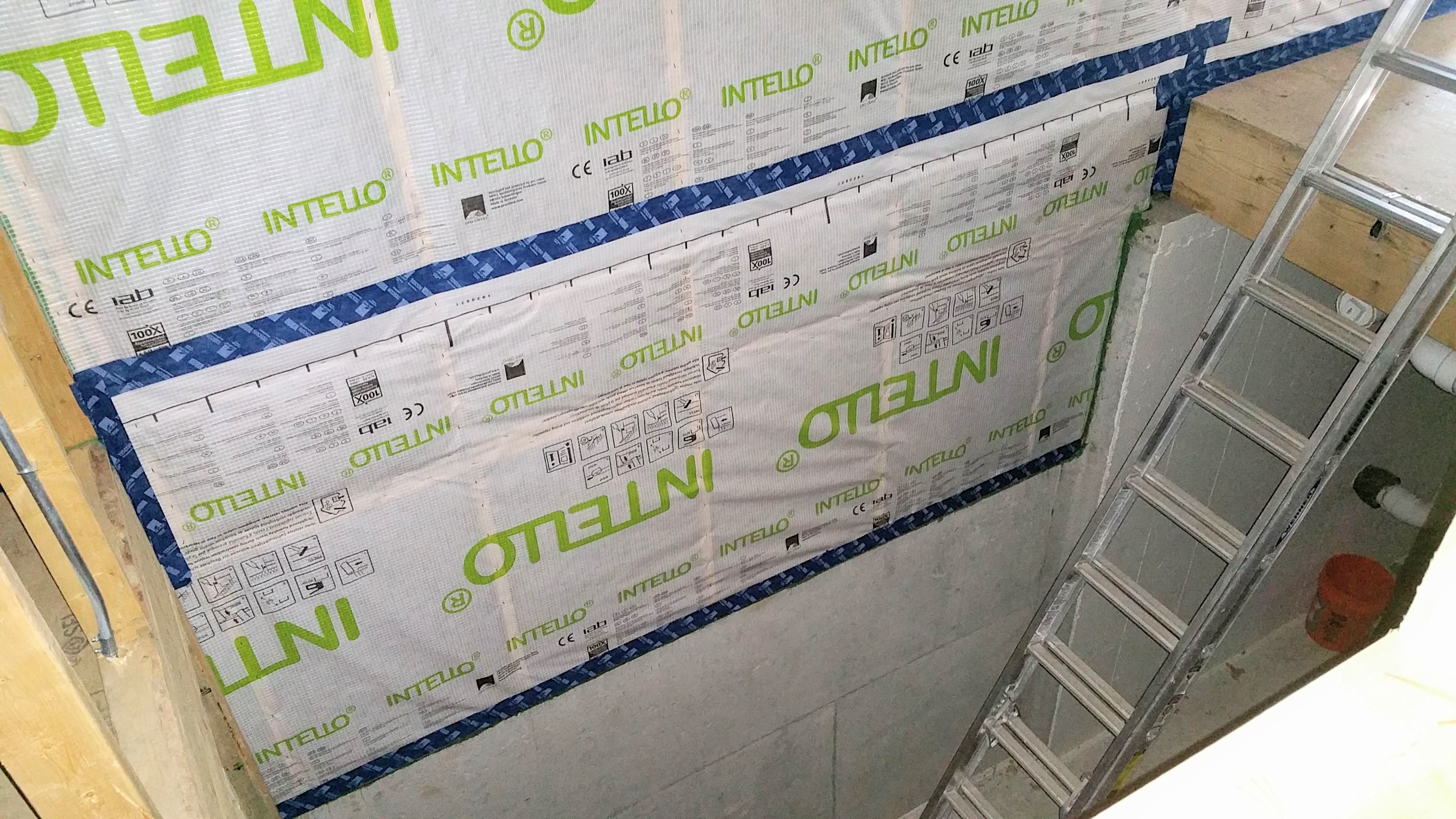
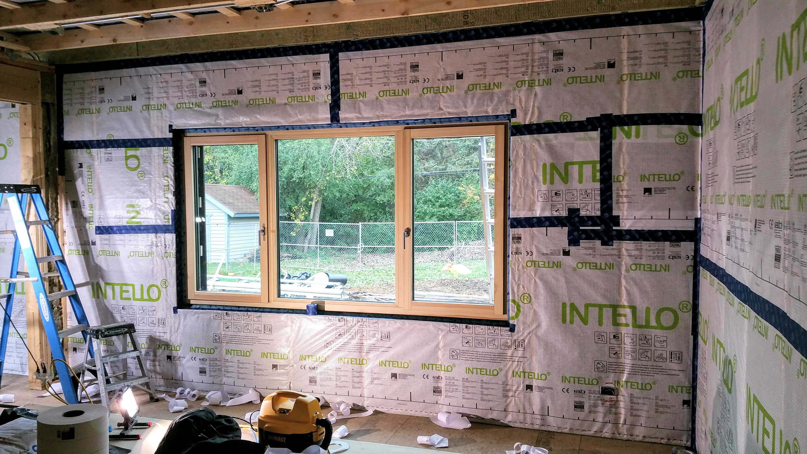
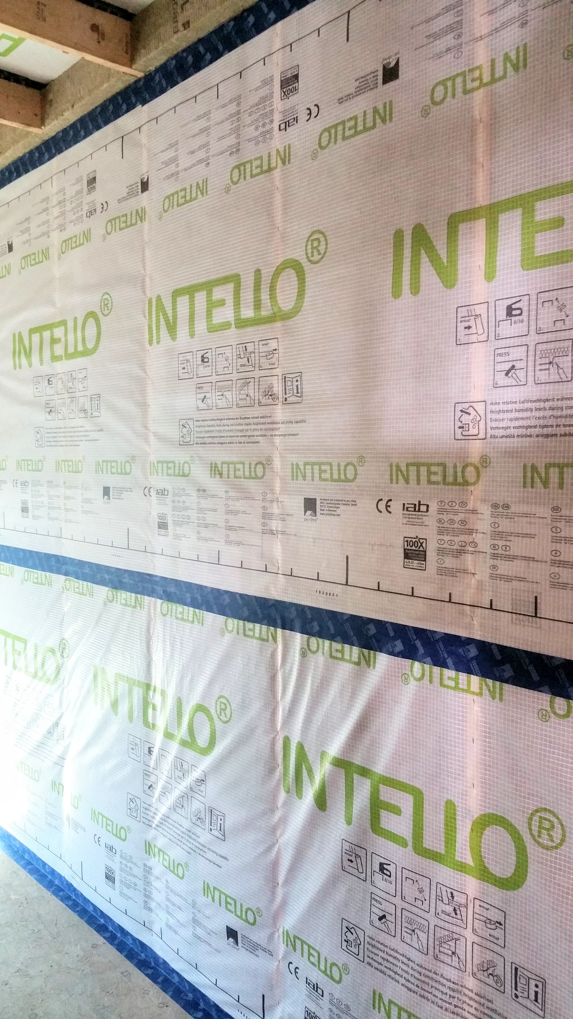
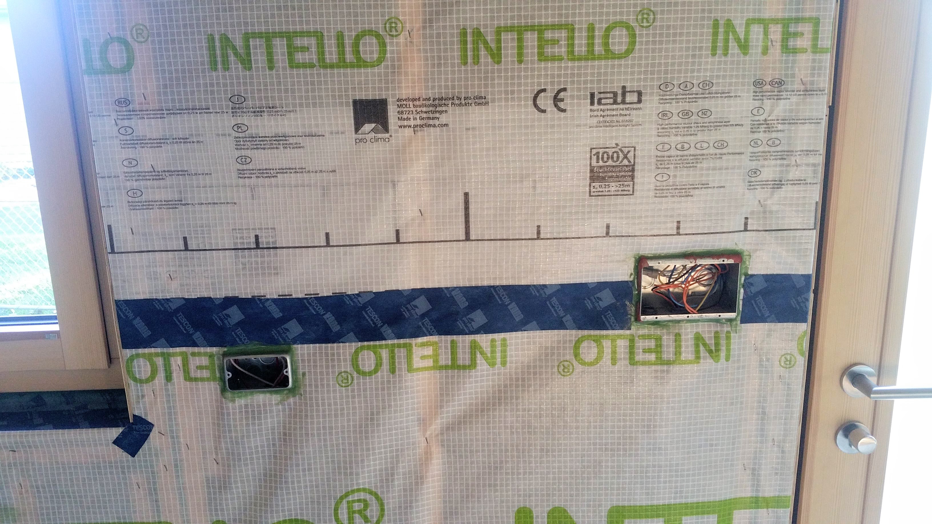
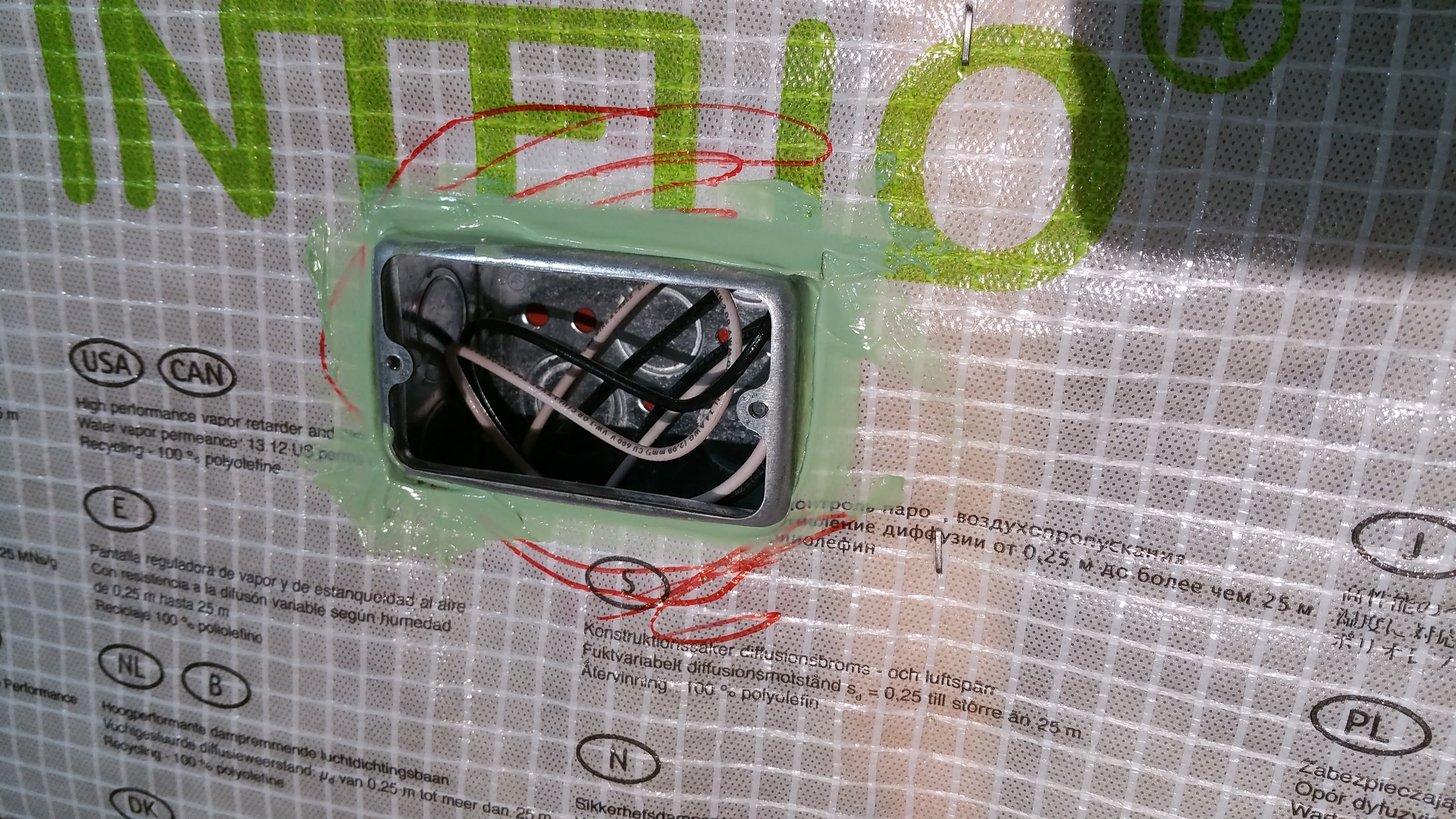
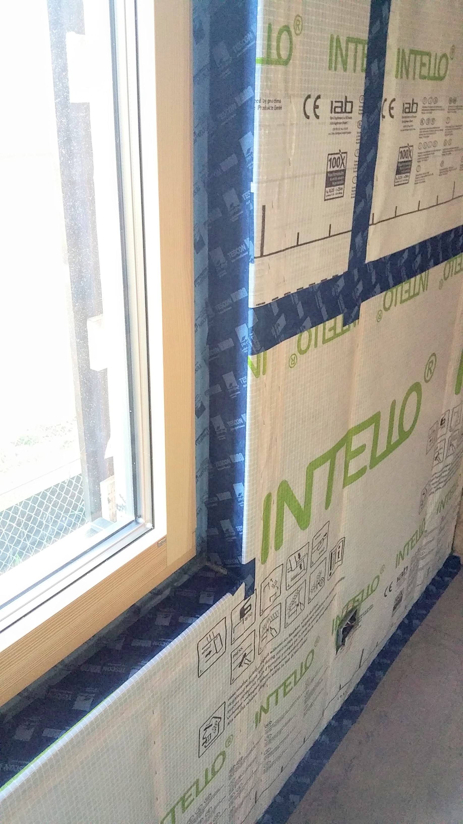
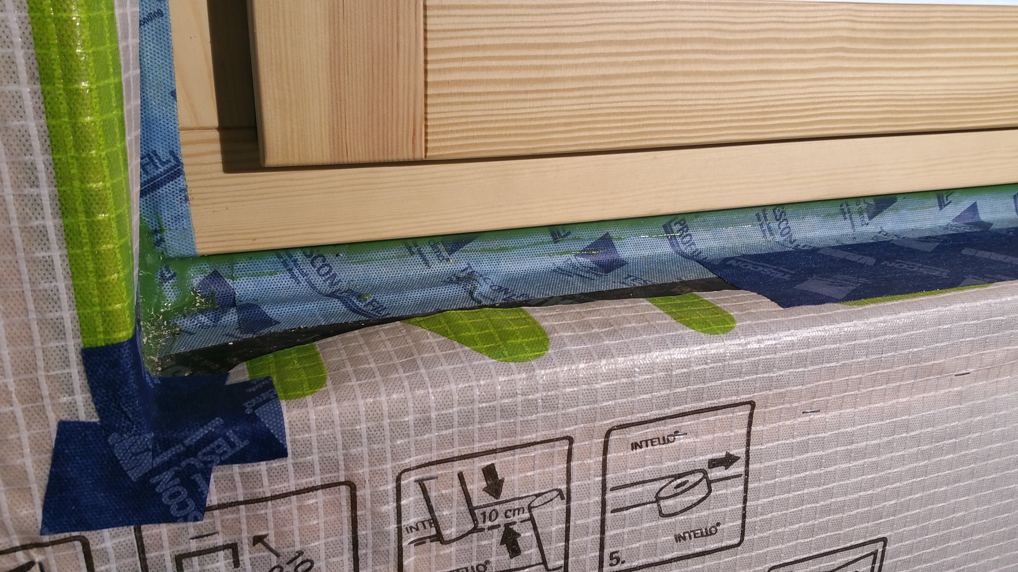
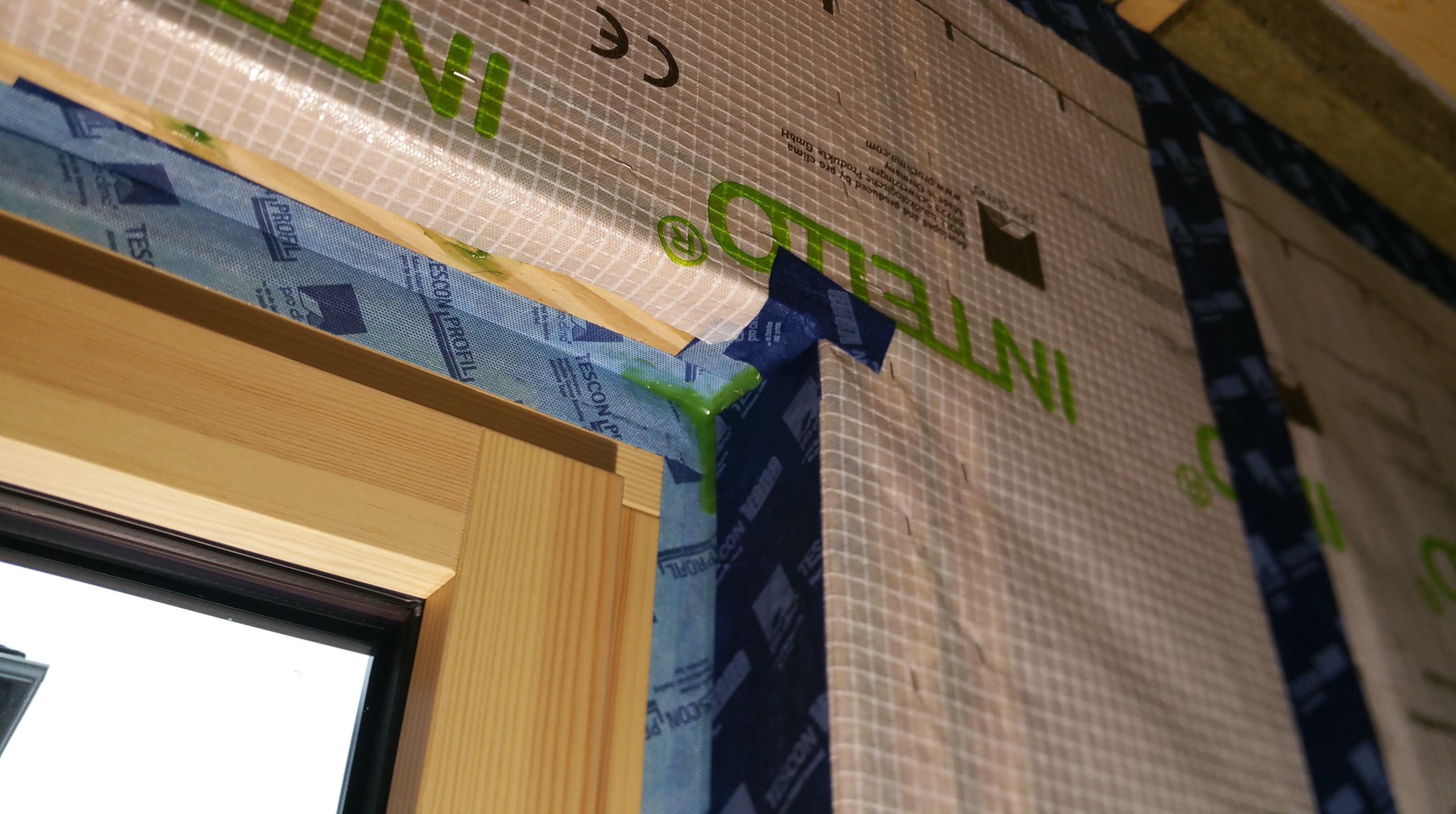
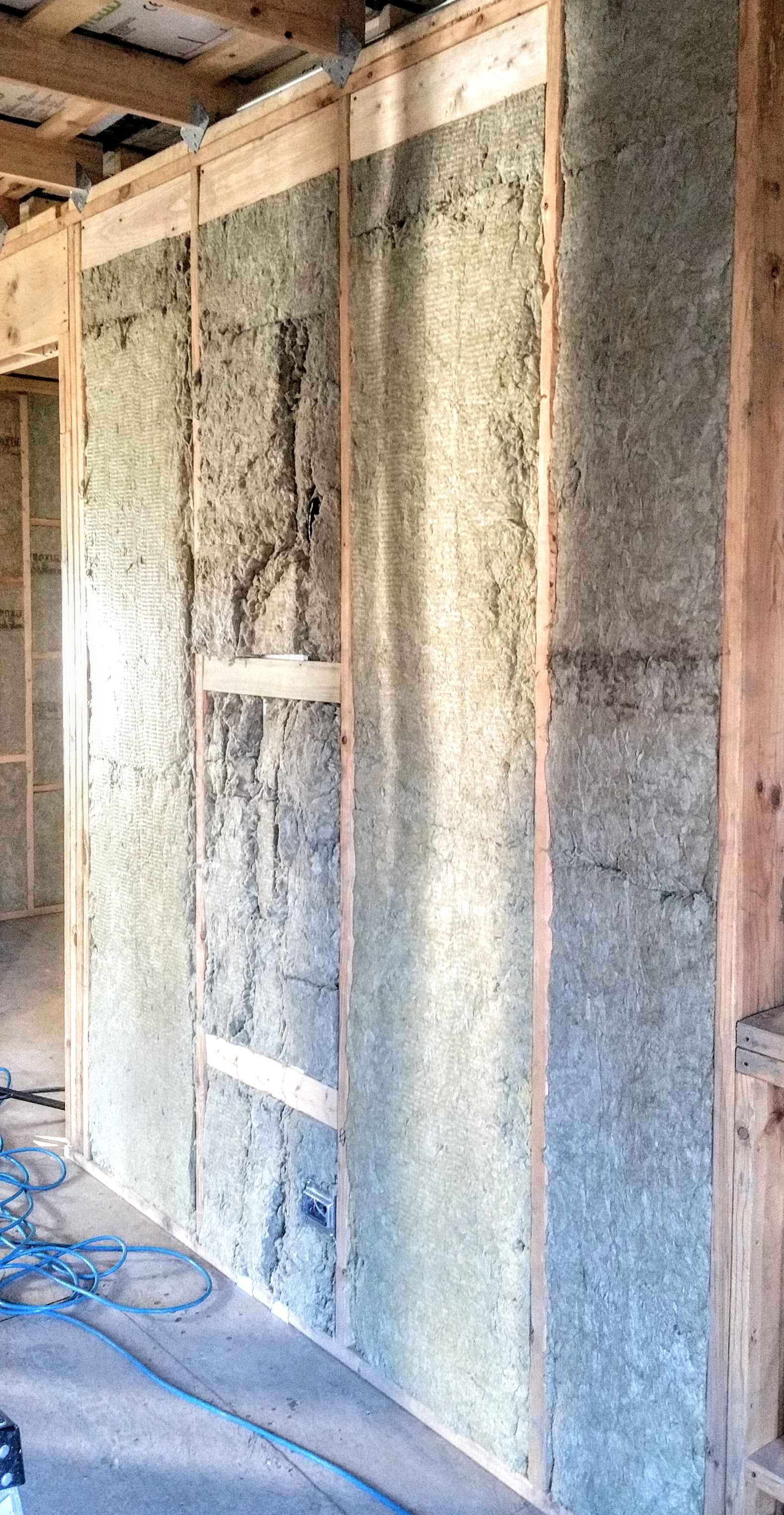
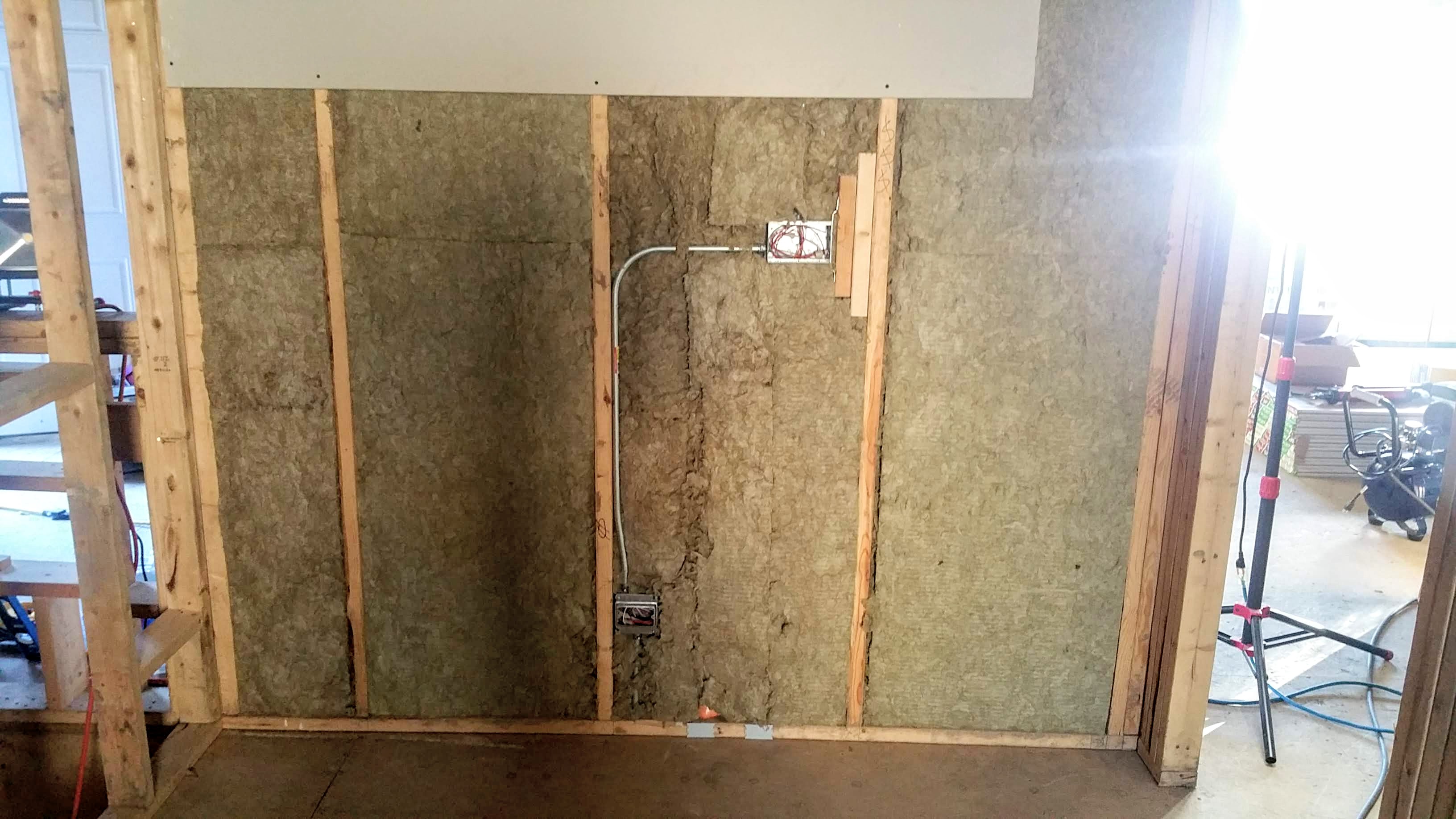
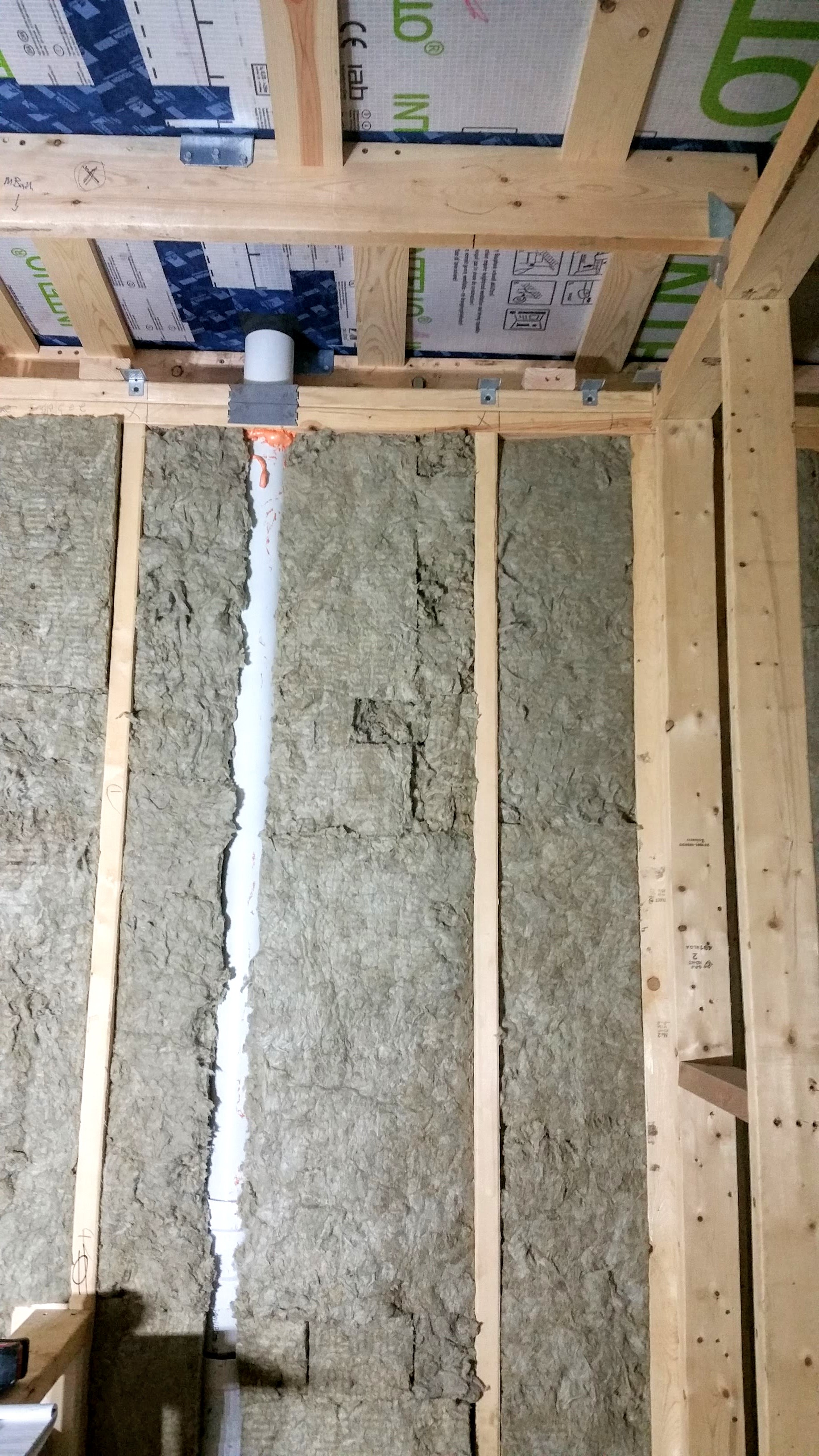
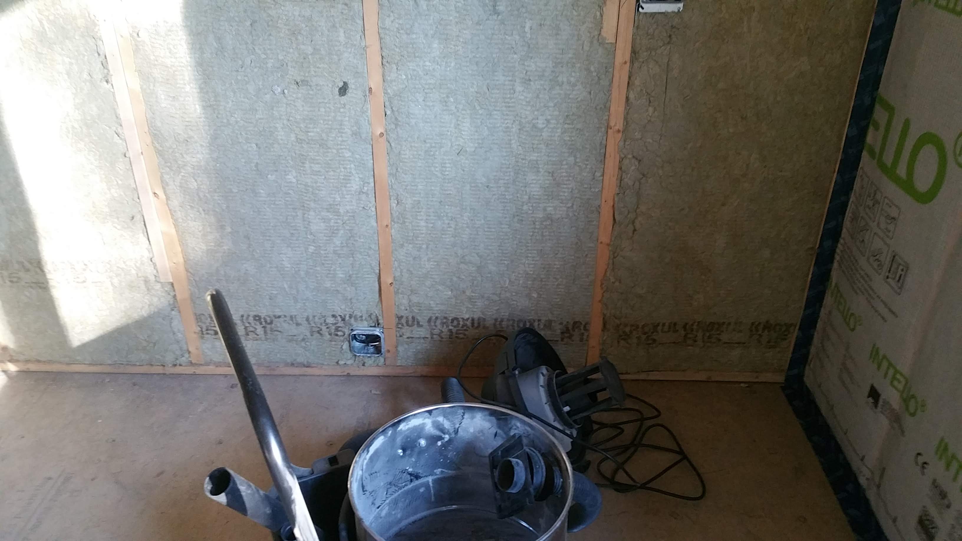
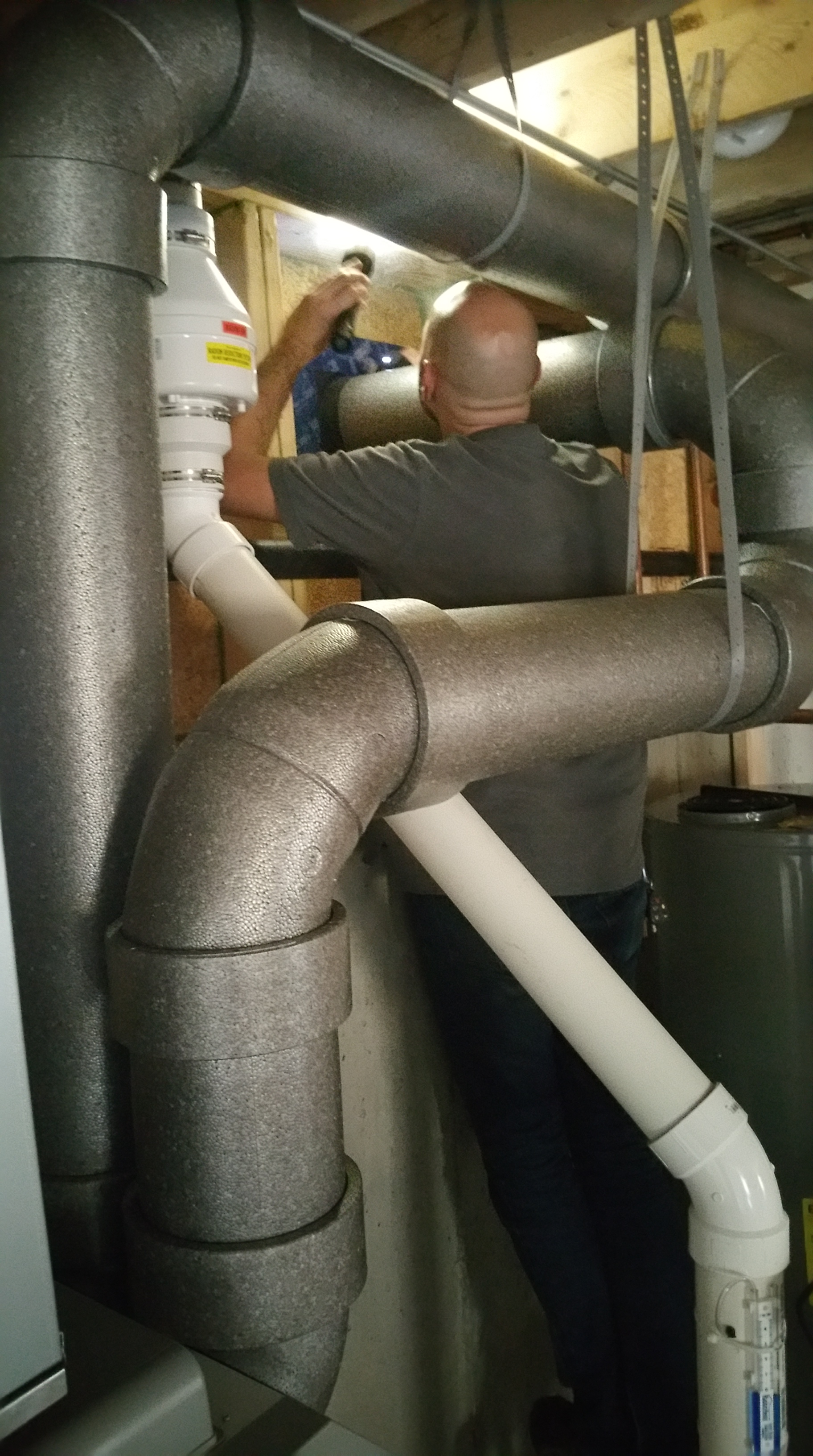
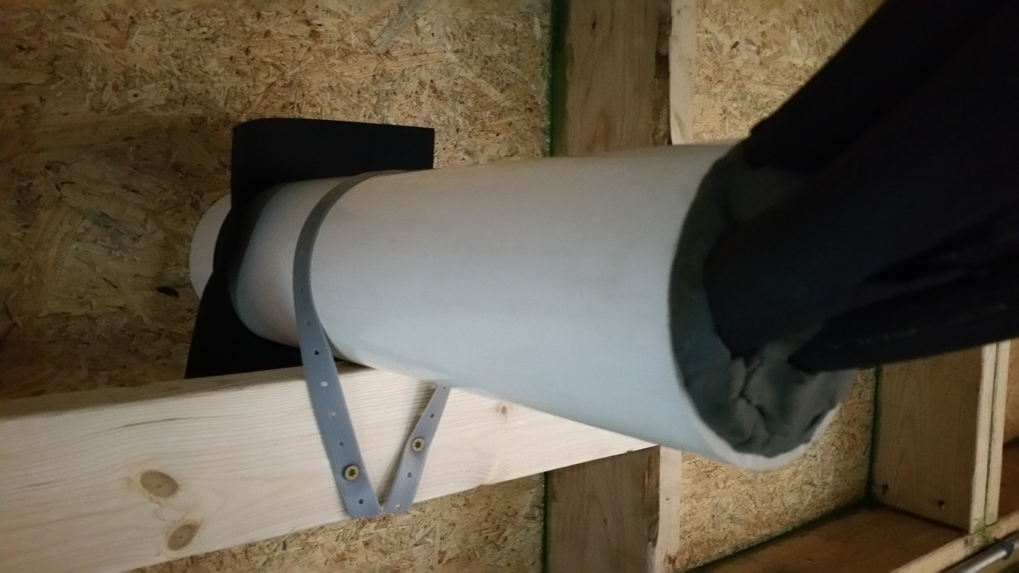
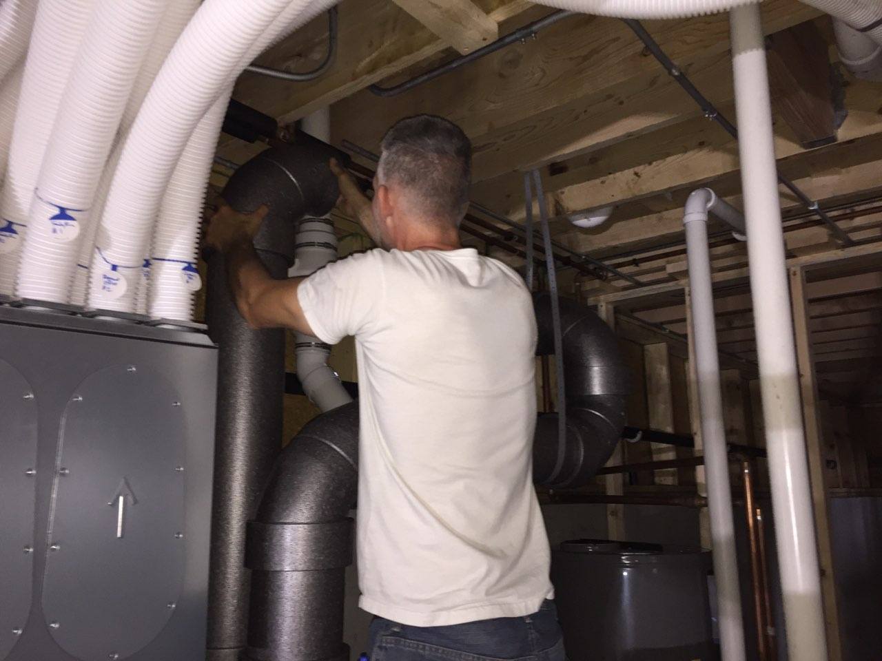
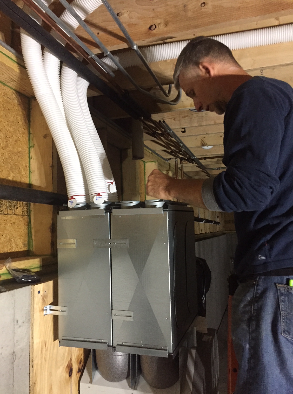
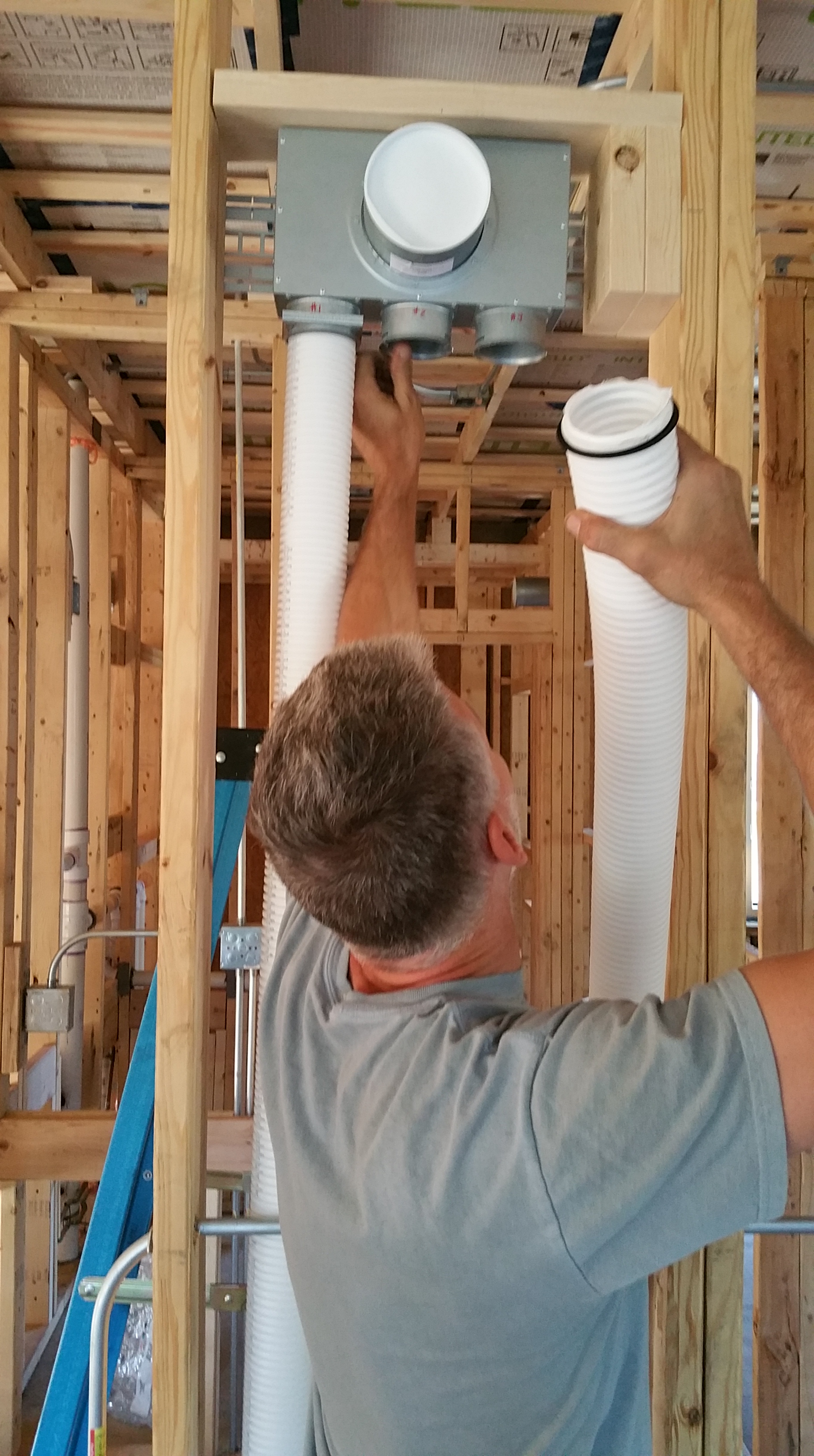
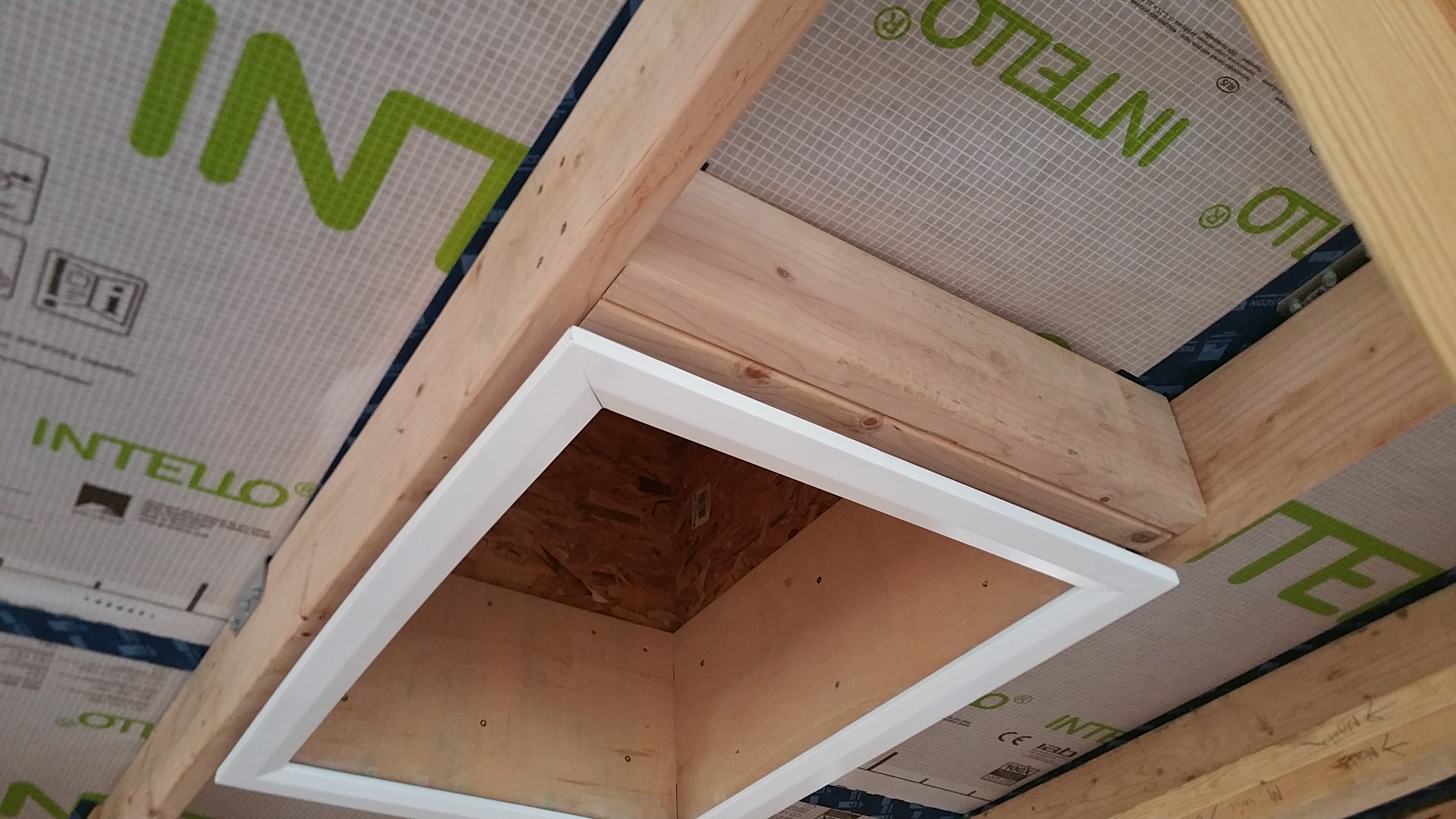
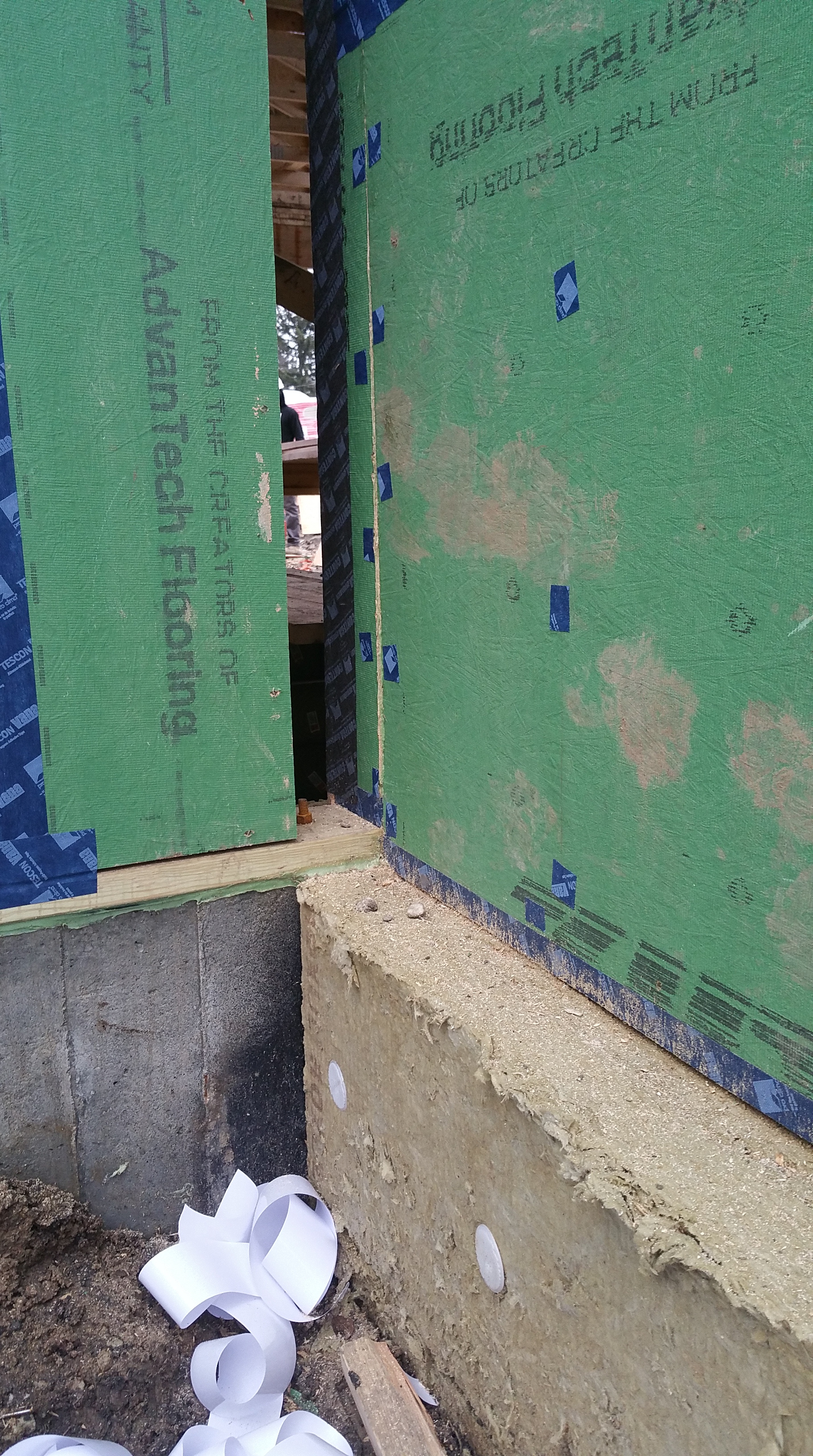
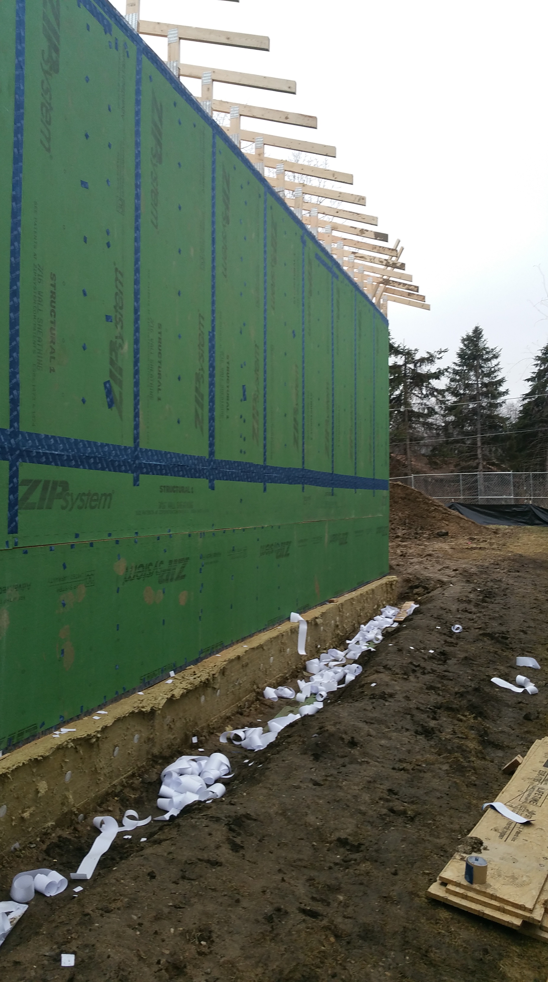
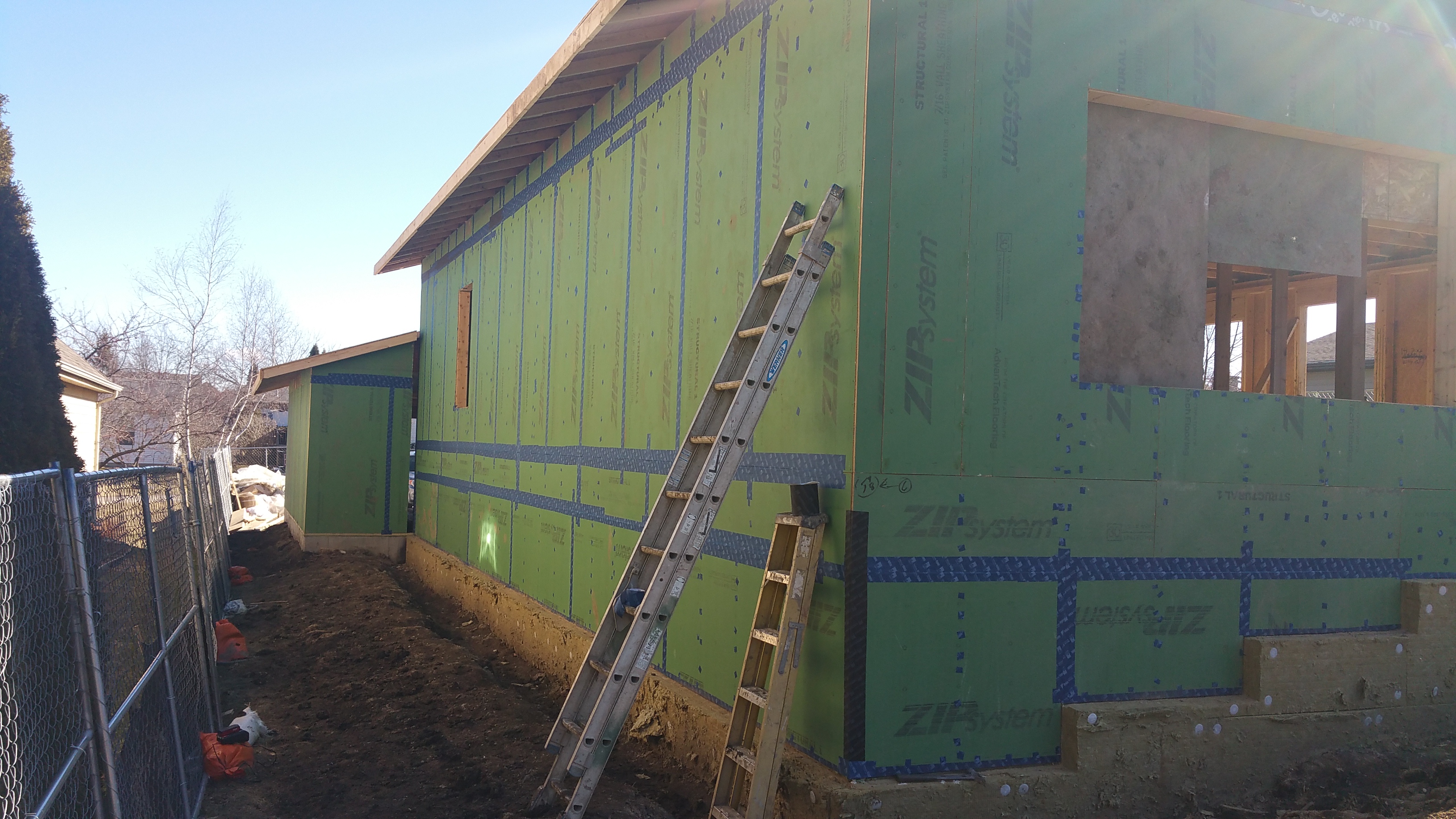
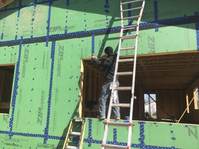
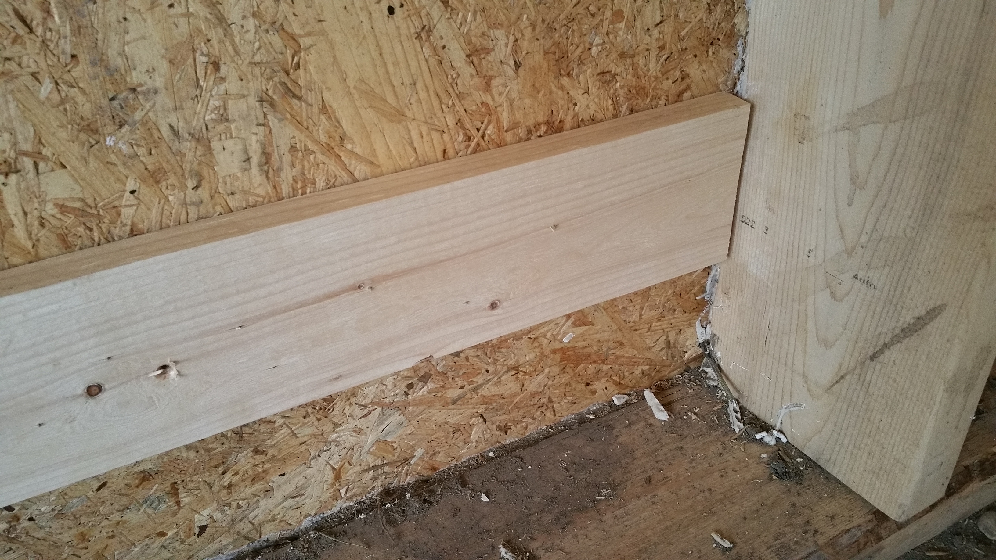
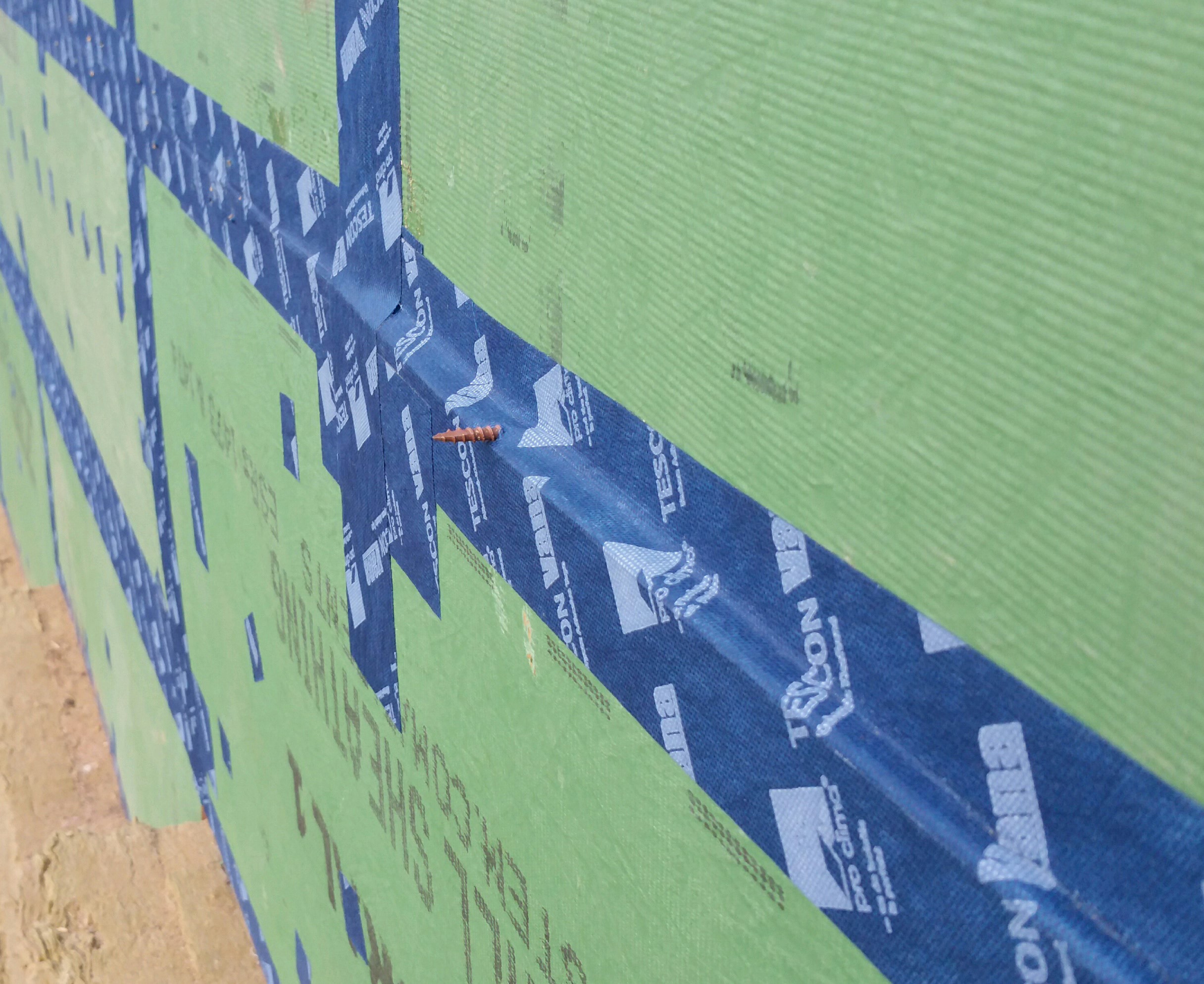
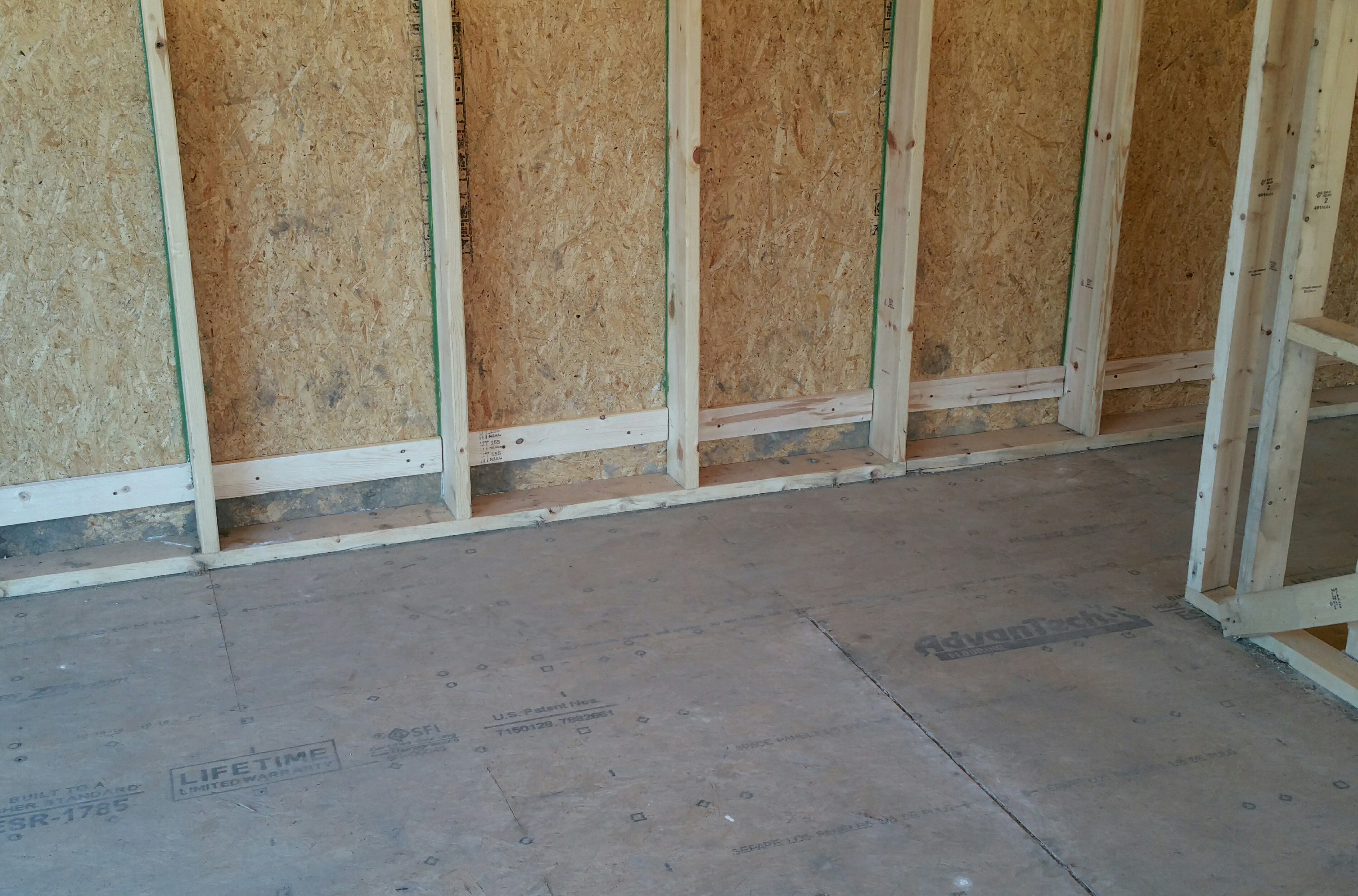
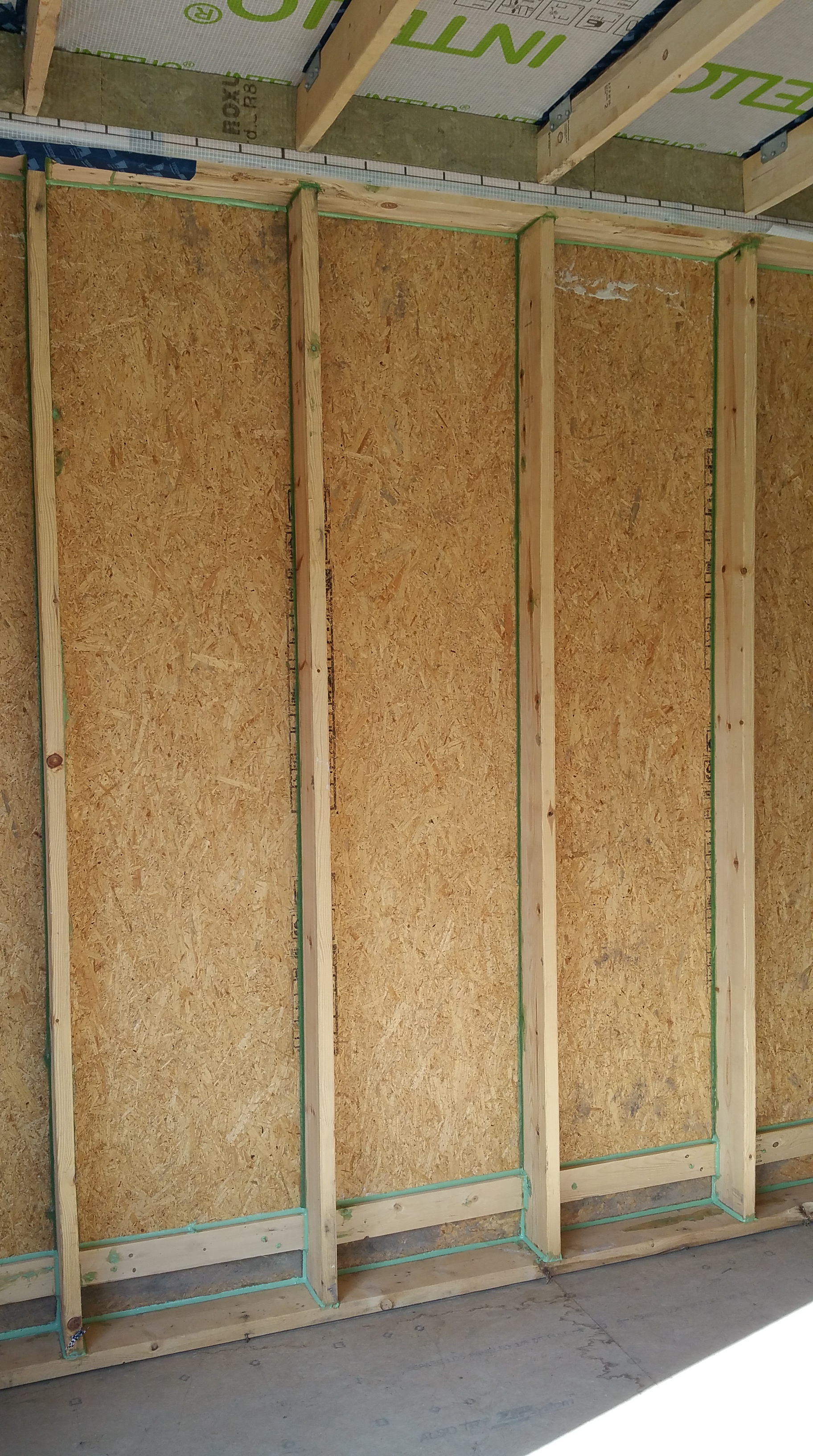
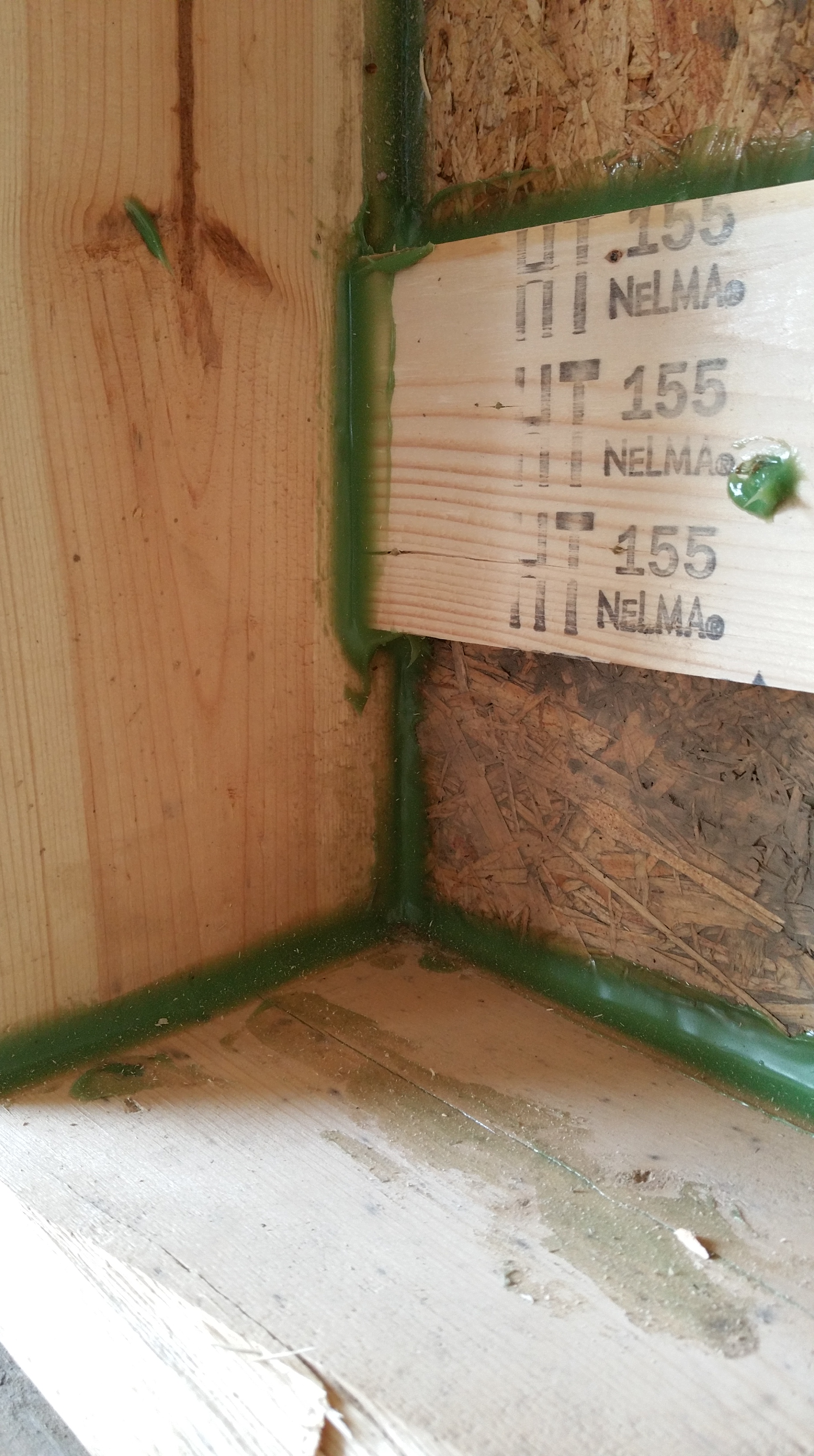
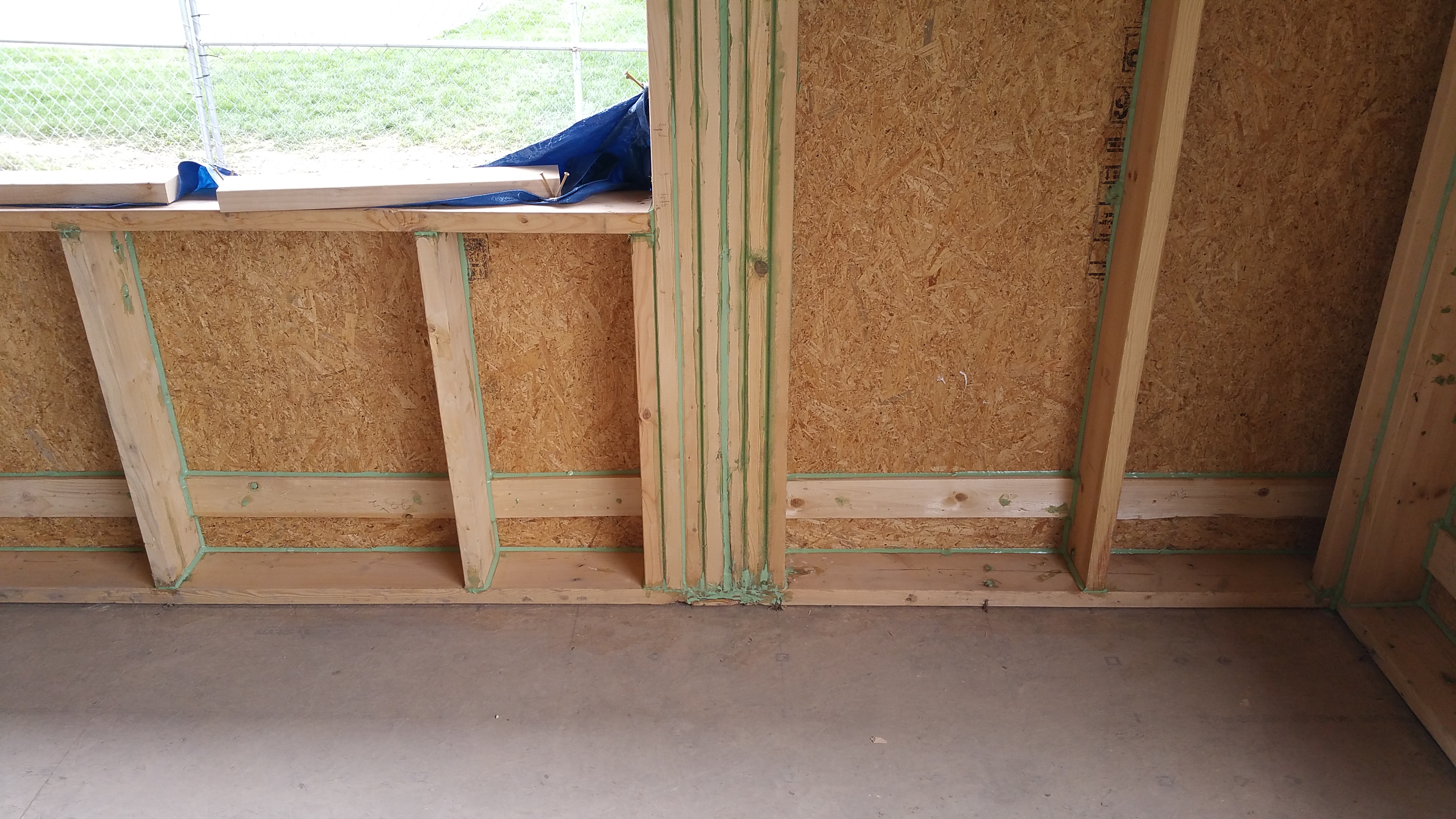
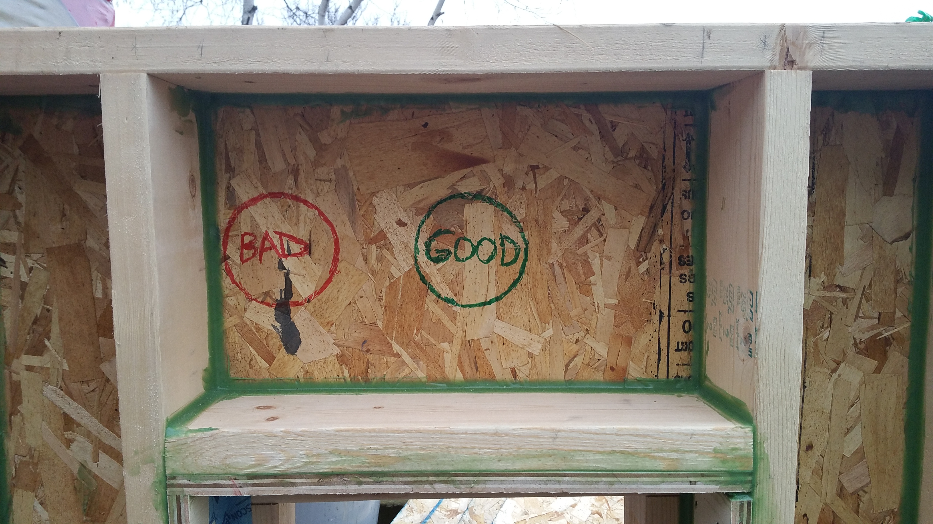
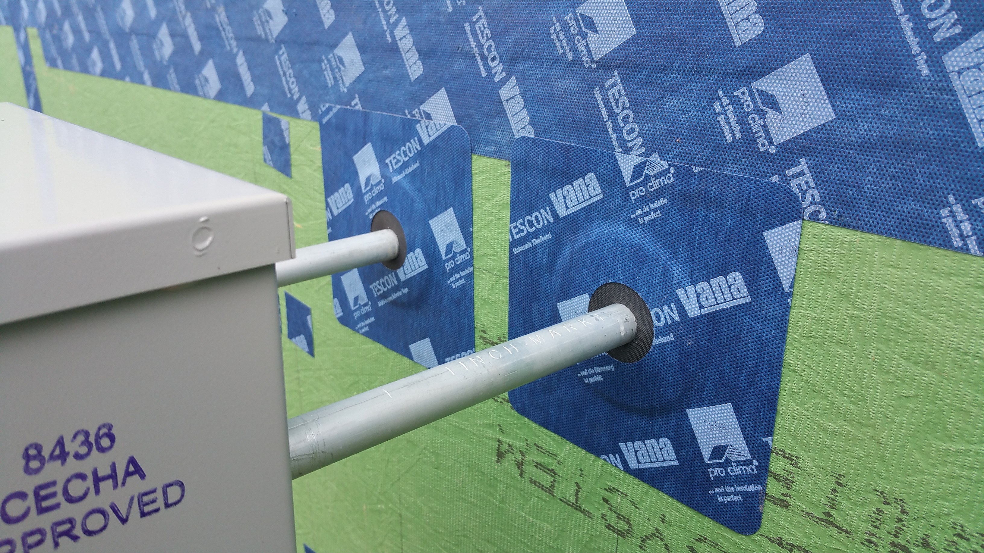
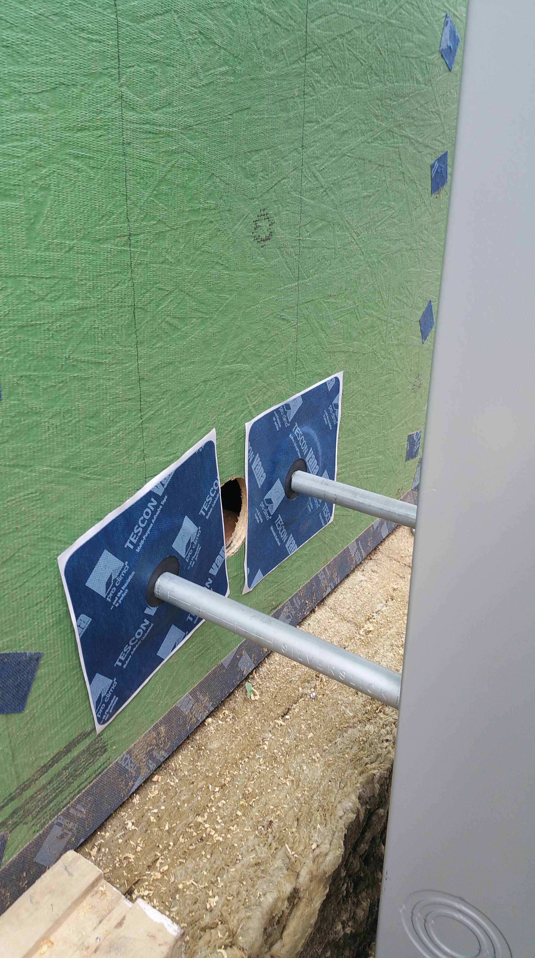
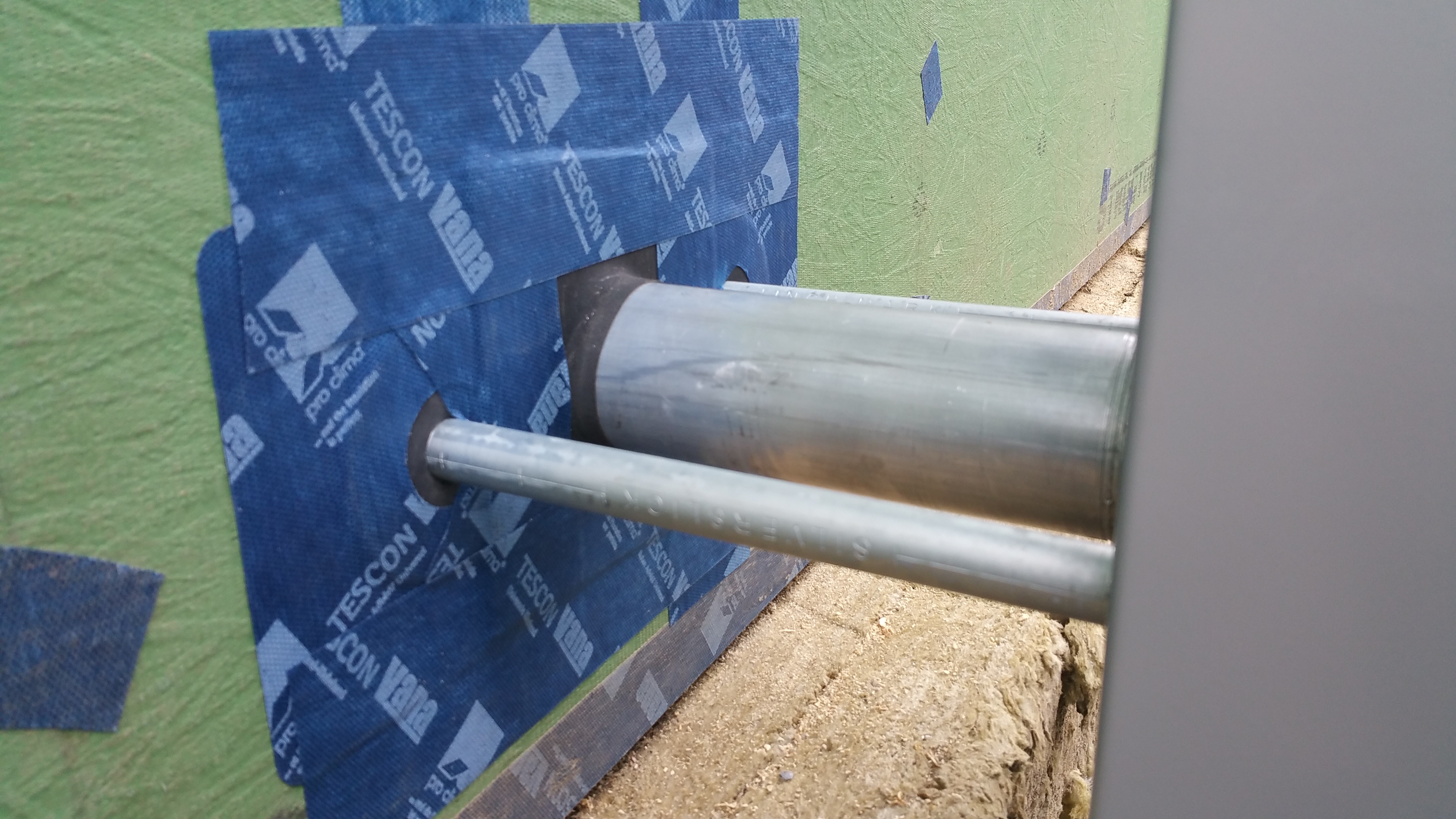
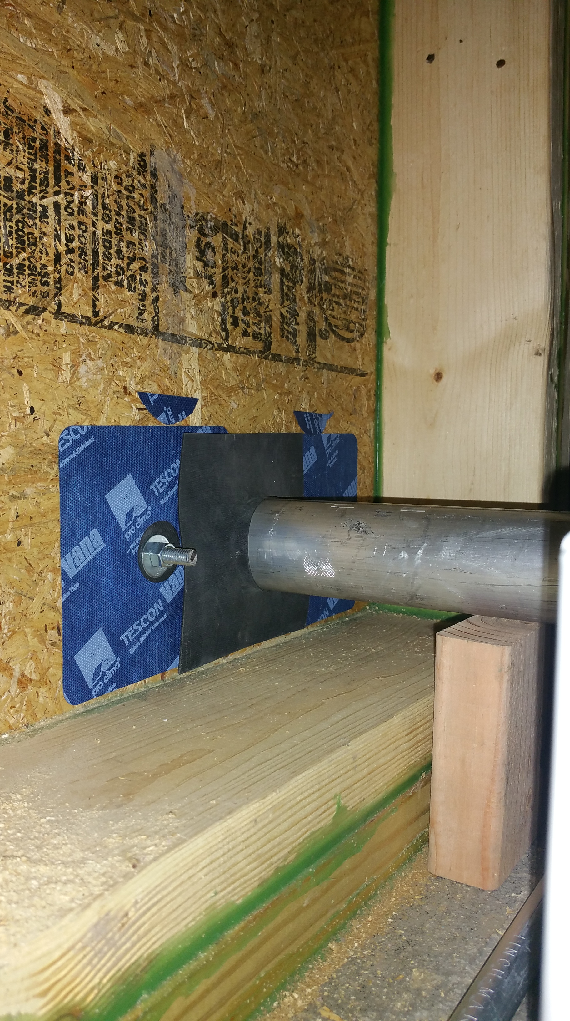
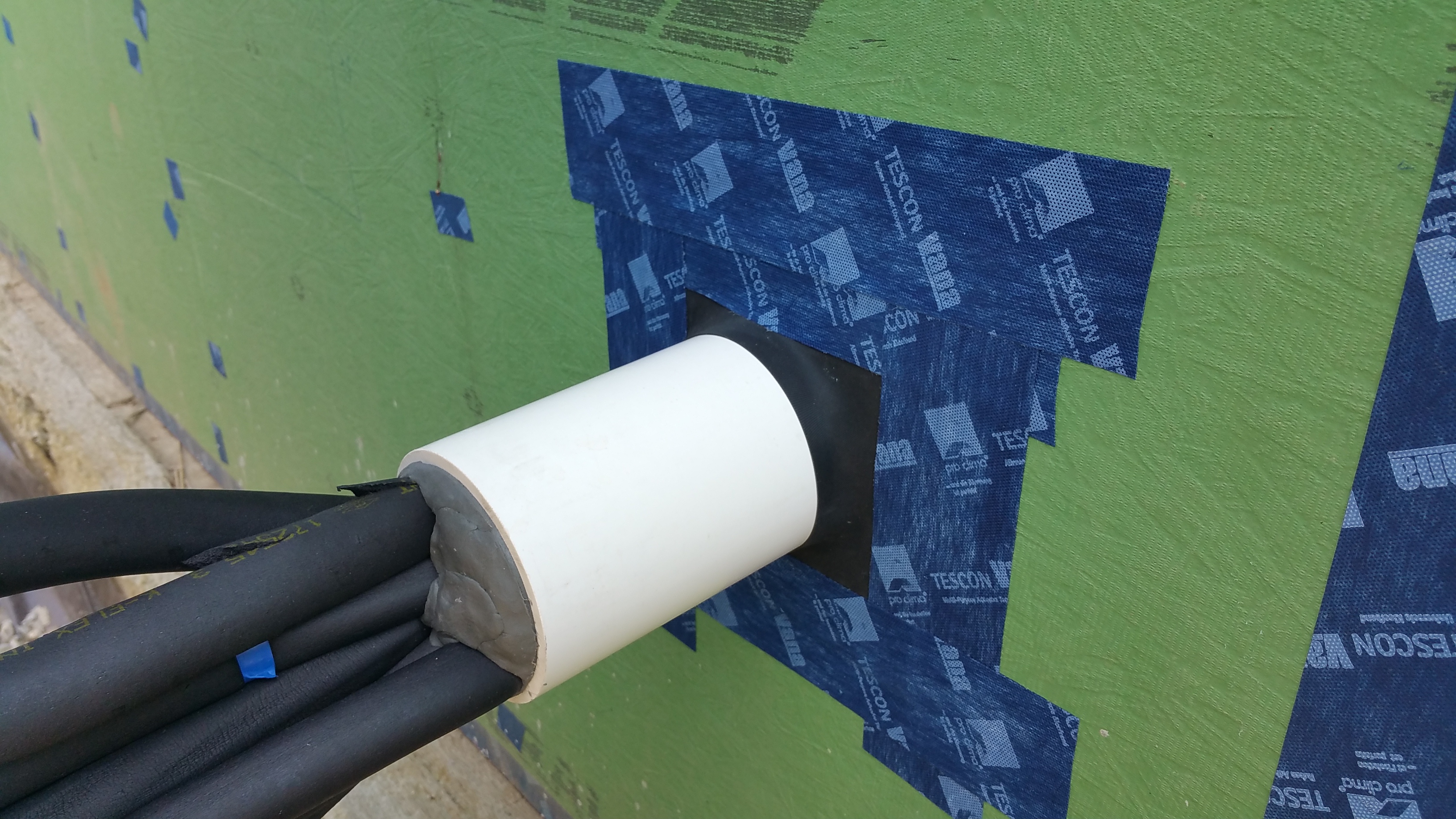
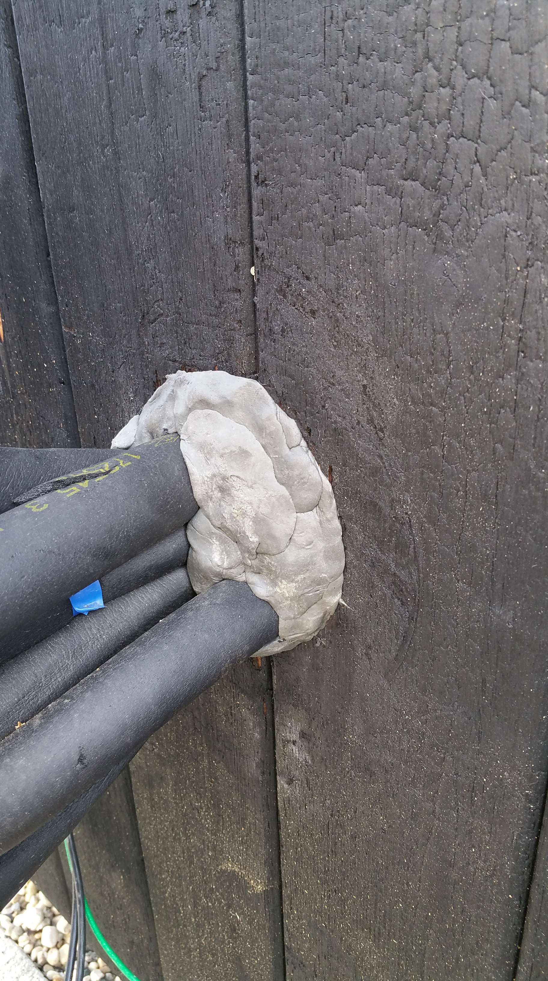
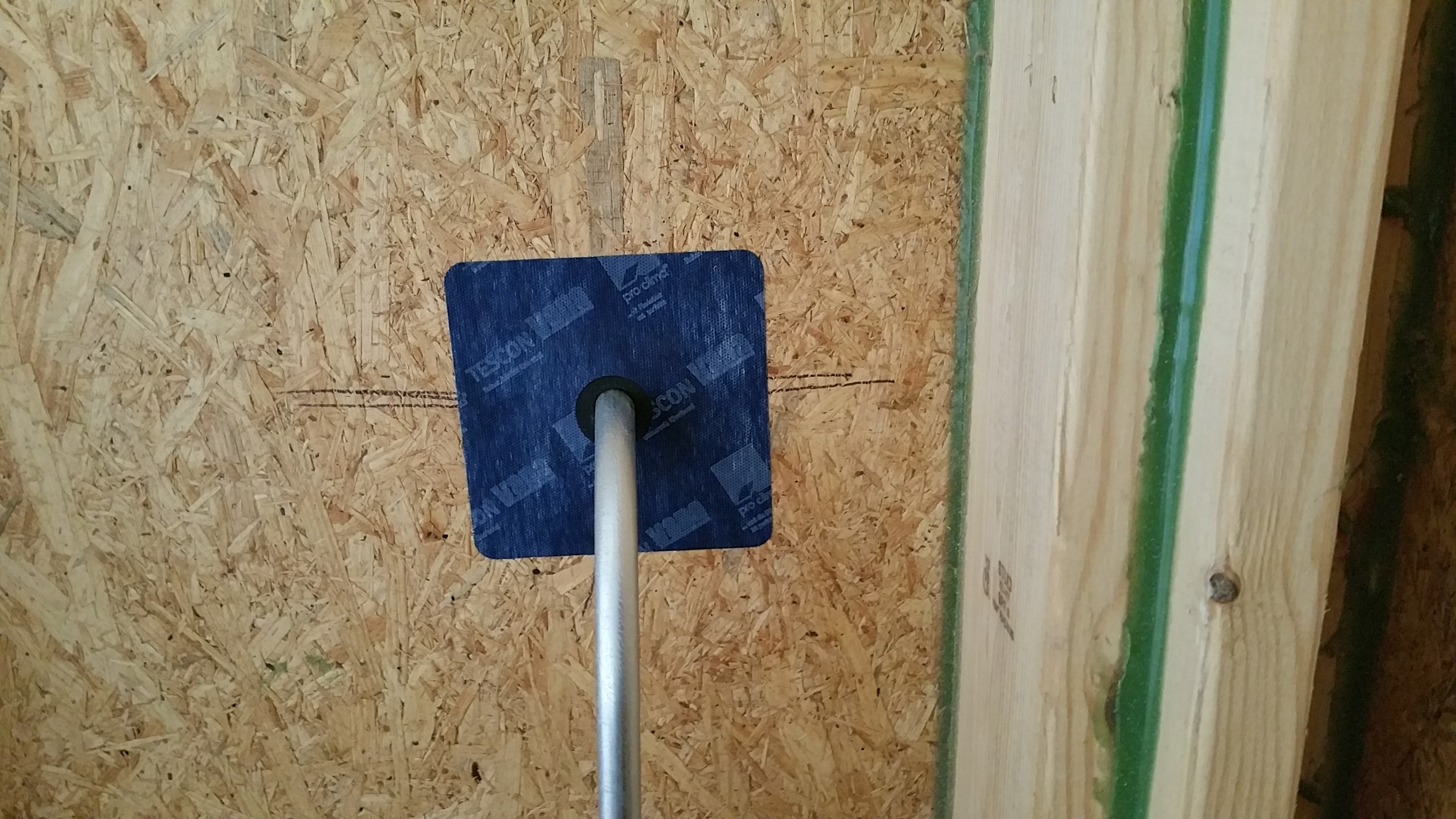
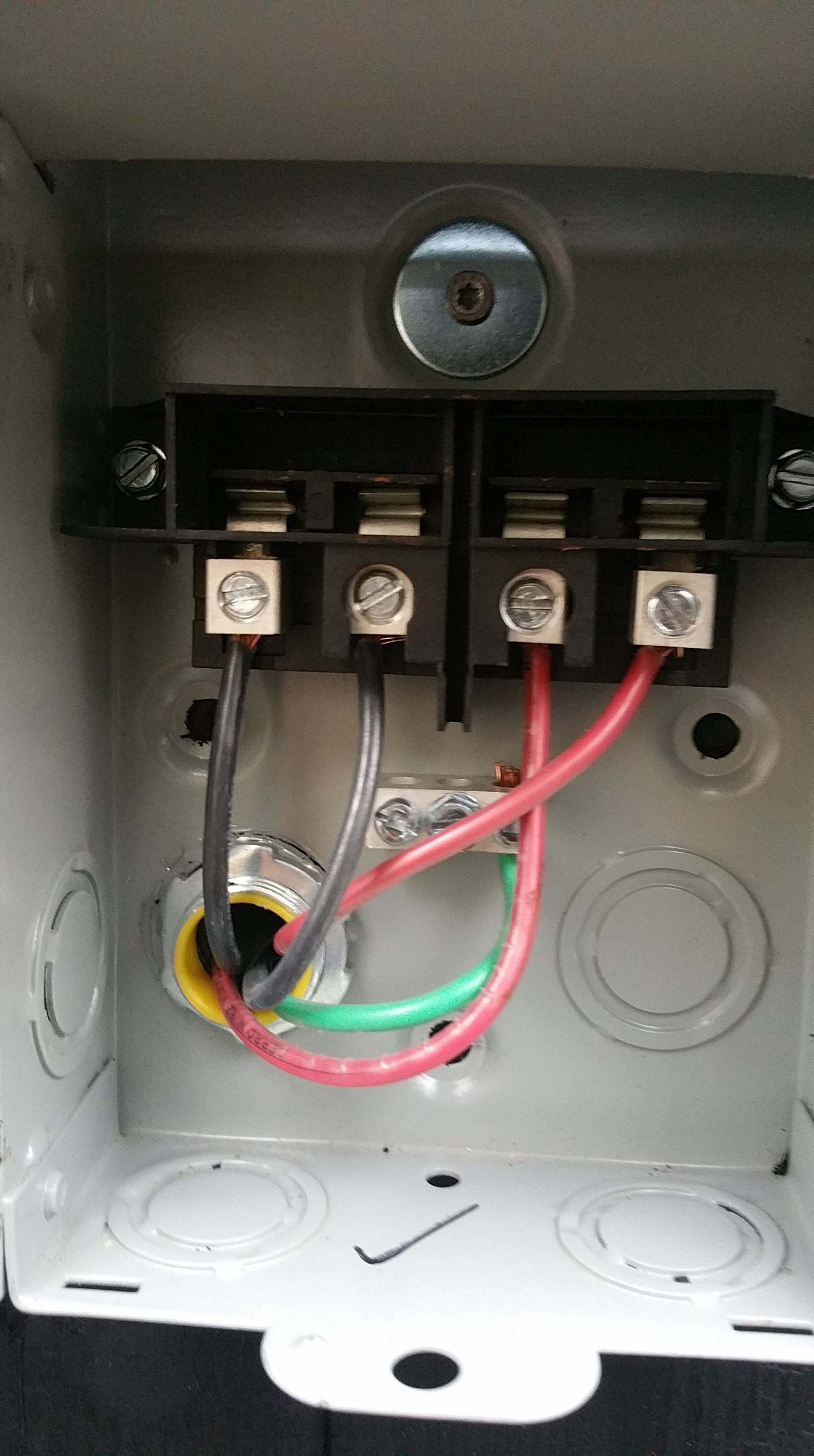
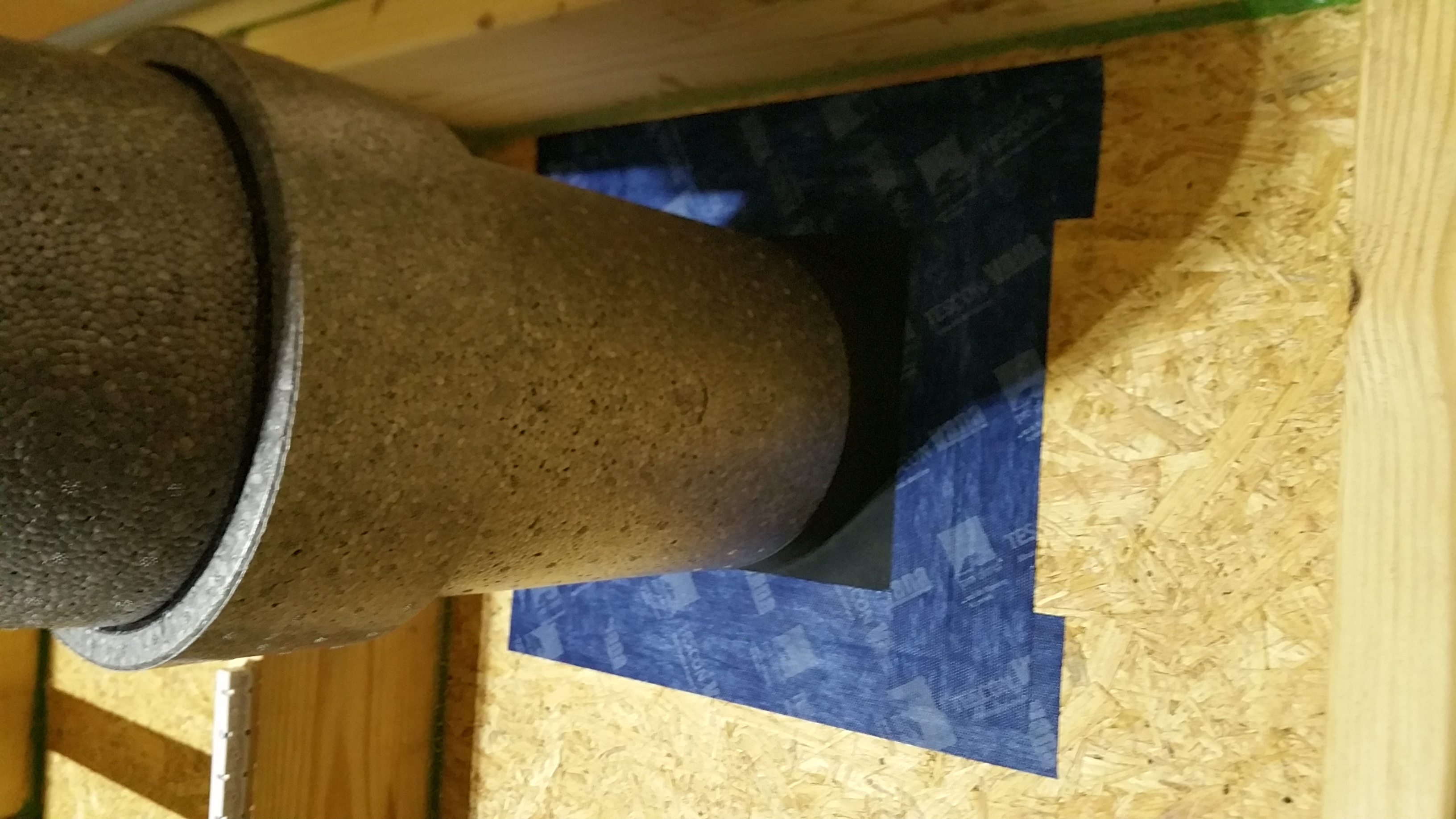
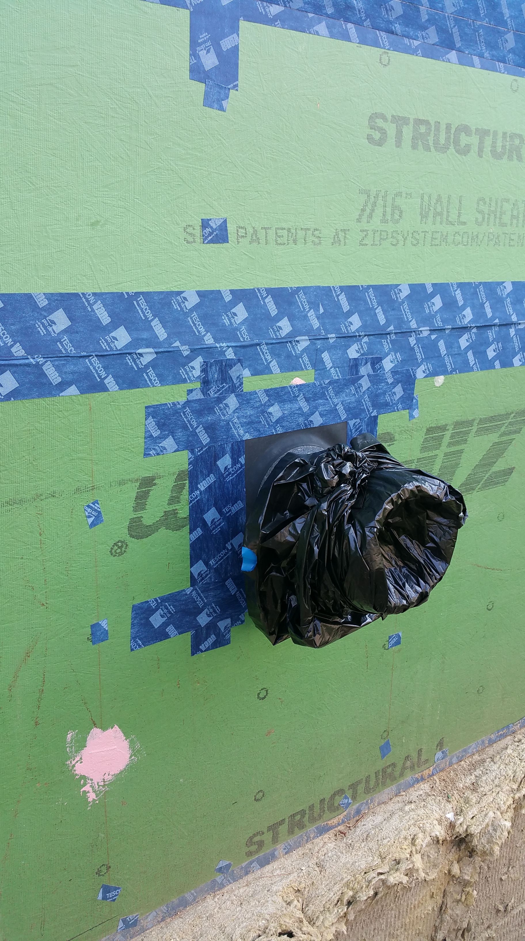
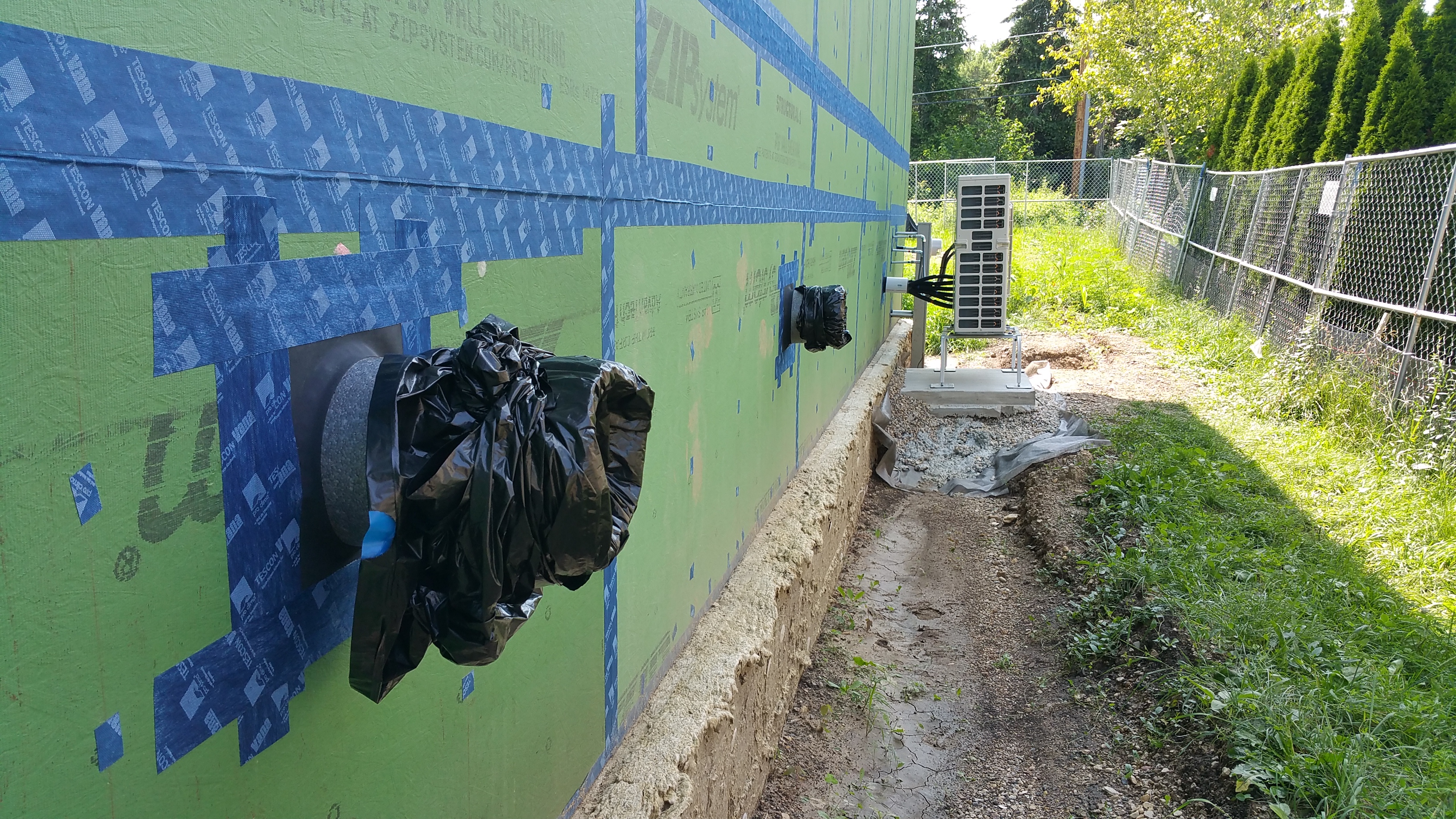
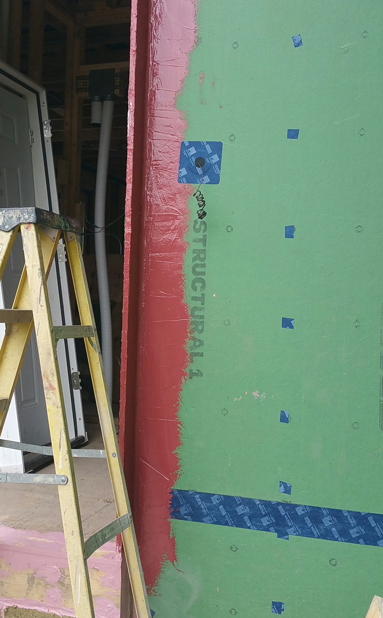
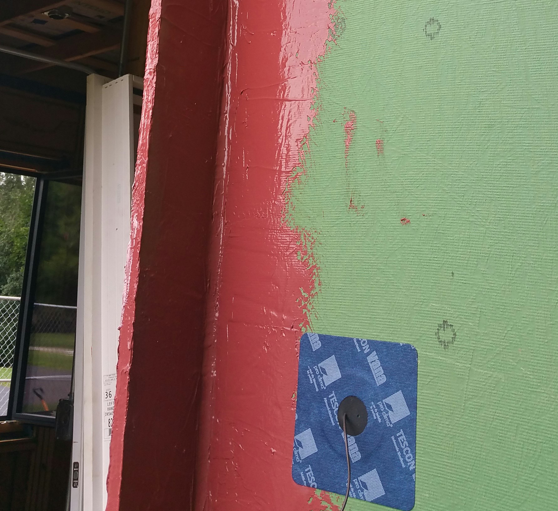
Passive House, as a building strategy, requires meticulous air sealing, along with ample amounts of insulation, carefully placed to eliminate or reduce the impact of thermal bridges through the building envelope. Once the air barrier of the building has been established, it requires mechanical ventilation to meet IAQ needs, along with high performance windows and doors to avoid undermining all of the air sealing and insulation.

details around a passive house window
Air sealing, water proofing, and thermal elements come together around one of our high performance windows.

All of these elements together, if successfully managed and implemented, should achieve a building that requires significantly less energy to operate and maintain at comfortable temperatures than any conventionally built structure of similar size and shape.

The Visitor enjoying some early morning solar heat gain through our kitchen window.

With a ‘conservation first’ approach (i.e., extensive air sealing and insulation), the goal is to reduce total heating and cooling demand as much as reasonably possible (while maximizing occupant comfort), with the possibility of adding renewables like solar or wind as mostly an afterthought to further reduce, or eliminate entirely, the remaining energy demand of the structure. It also typically means going all electric, so in our case it meant no natural gas (the normal fuel source in our area for a furnace and a hot water tank).

So far, our 11 panel 2.9 kW system has been averaging between 3,500-4,000 kWh of solar production per year.

A Passive House structure, by design, should use significantly less energy than any conventionally built counterpart of similar size and shape. This includes lighting (normally assumes only LED fixtures will be used) and other plug-in loads (e.g., Energy Star appliances), as well as hot water (typically a heat pump hot water tank, or a newer product like Sanco or Chiltrix).

Unfortunately, these loads are relatively ‘baked-in’, even for an existing, conventionally built home. For instance, a hundred year old home could switch all of their light fixtures to LED bulbs, replace old appliances with new Energy Star rated models, and change out a gas-fired or a conventional electric hot water tank to a high-efficiency heat pump model. In effect, they’d have pretty much the same reduction in energy use as a brand new certified Passive House of similar size and layout for these particular sources of energy demand. As a result, the real opportunities for driving down energy use in a Passive House are in the heating and cooling loads (mainly due, of course, to the extensive air sealing and insulation levels).

heat pump mounted on wall with artwork
On most days the 15,000 Btu head in our kitchen and family room handles all of the heating and AC needs for our entire house. We have two additional heads in our bedrooms (9k and 6k Btu respectively), but they’re rarely used apart from the coldest and hottest days of the year.

Although there has been some moving of the goal posts as the Passive House programs have evolved over time, they remain challenging targets to meet.

Here are the current PHI requirements: Passive House Checklist

In the case of PHIUS, the requirements have gone through several iterations, for instance, PHIUS+ 2015, PHIUS+ 2018, and most recently a fairly dramatic change to a prescriptive track to seek certification with far less onerous levels of paperwork and data collection required.

Overall, regardless of which model is pursued, PHI or PHIUS, the intent is to dramatically reduce the overall energy use of buildings by emphasizing the importance of air sealing, insulating to levels that exceed current code requirements (in most cases), along with quantifying things like thermal bridges, heating and cooling demand, and peak heating and cooling loads. The issue of energy demand or energy use is further complicated by the distinction made between Primary/Source and Site Energy.

Additionally, there’s been a growing consensus regarding the need to incorporate renewables in these building strategies, both in terms of financial feasibility and in terms of further reducing (or even canceling out altogether) net energy demand. And while it’s true that Net Zero is fairly straightforward to achieve (assuming needlessly large PV arrays are not utilized as a short-cut), it does require a commitment to meticulous air sealing and quantities of insulation that, along with the in-depth energy modeling, unavoidably add cost to any construction budget.

passive house mechanicals
Zehnder ERV, Rheem HPHW tank, radon pipe with fan, and battery back-up sump pump. Elements that support proper moisture management, IAQ, and HVAC needs.

The opportunity for significant energy reduction also correlates with the size of the project. Because of form factor ratios, the larger the project (assuming a compact form is mostly maintained) the more energy a structure stands to conserve. This is why larger institutional, multi-family projects, or corporate-sized projects stand to be the biggest winners when it comes to the purported benefits associated with Passive House energy conservation.

energy use in a passive house
Outdoor heat pump compressor after the snow, but before the worst of the 2019 Polar Vortex.

If executed properly, low energy demand will mean considerable financial savings. These savings are cumulative, year after year, rather than just a one-off initial price break, with the added potential to increase should energy costs increase.

energy bills in a passive house

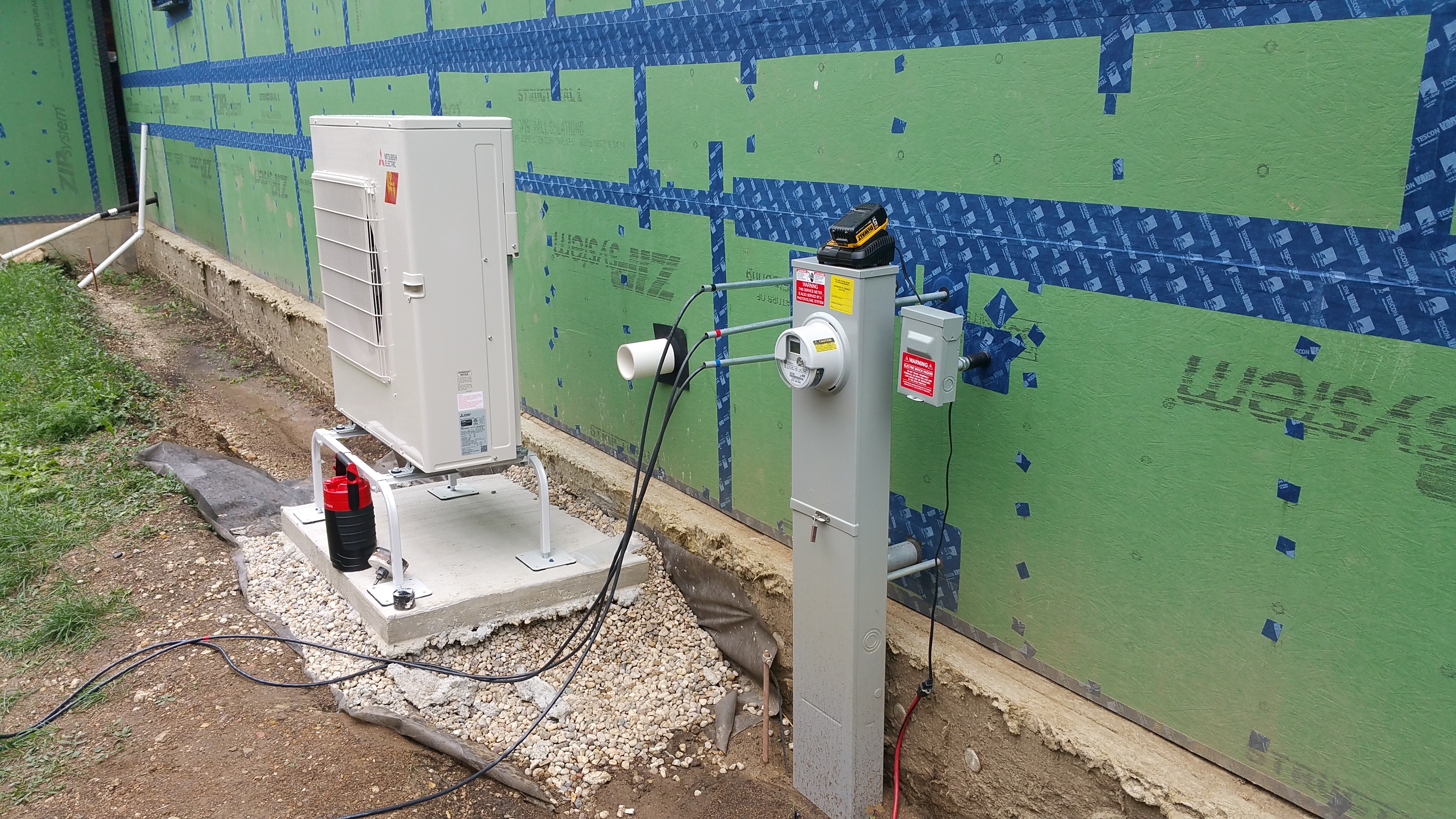
In addition, there is the potential for less upfront expenditures for HVAC equipment (less heating and AC demand — at least in theory — means smaller and more cost-effective equipment is required). In our case, in climate zone 5, where we get cold, dry winters and hot, humid summers, this didn’t prove to be the case. Combining the cost of our heat pump and ERV reflected roughly what we would’ve paid had we built a conventional home with a high efficiency gas furnace with a humidifier attached (fairly typical system in our area). Either way, it would constitute roughly a $20,000 expenditure for a house under 2,000 square feet. The level of indoor comfort, however, should be vastly different between a conventional and a Passive House build.

Even though occupant behavior can derail some of these projected performance outcomes, assuming that homeowners or tenants are reasonably educated on the best way to enjoy and benefit from the Passive House details, especially the HVAC systems (normally this means commissioning units and then mostly leaving them alone in terms of settings), this should not be a stumbling block for most builds.

energy use in a passive house

While all of this becomes more challenging with a smaller, more compact build like our 1,500 square foot single-family home, the possibility of significantly lowering energy demand is no less real, along with the cost savings. Not to mention the level of occupant comfort, which I personally feel is the main selling point of the Passive House building principles.

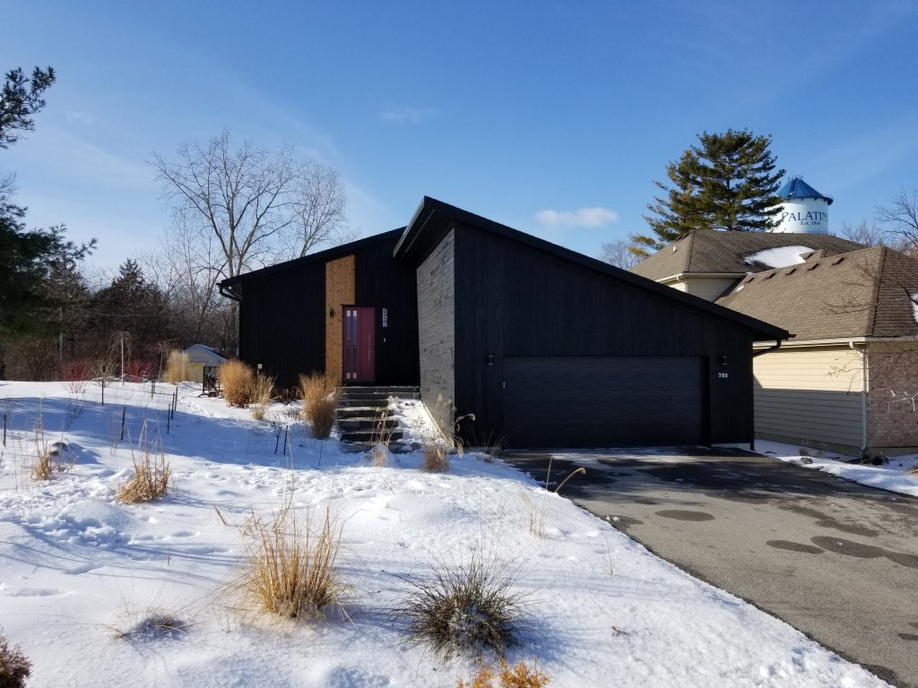
Some Background Information on Our Home

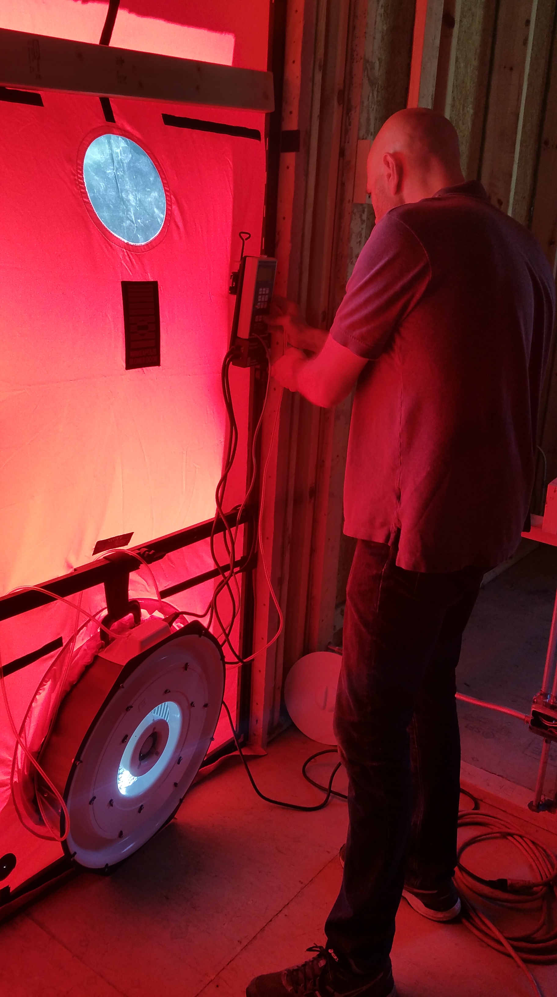
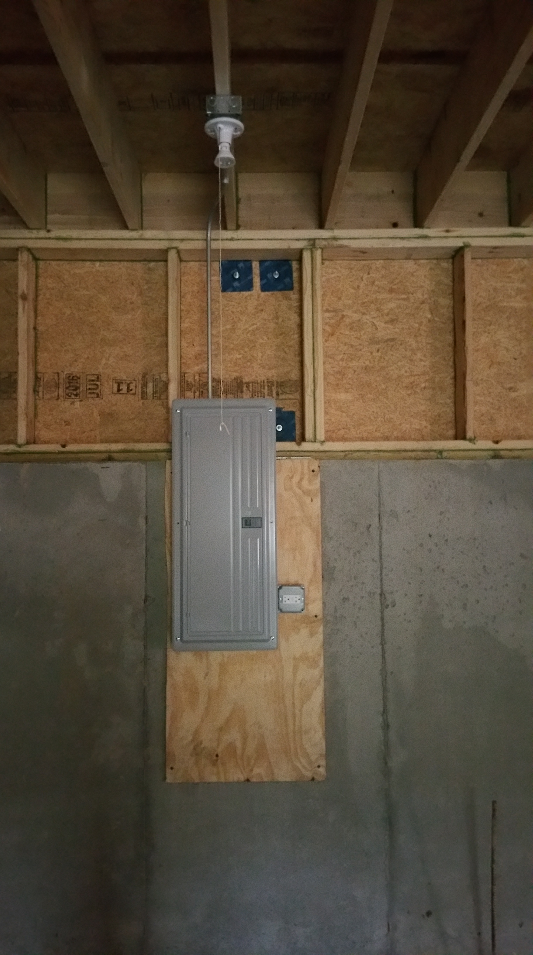
A quick summary of our build would include our blower door score of 0.2 ACH@50 (106 cfm@50), along with the following R-values for the structure:

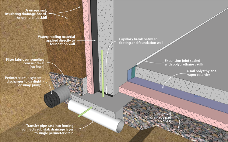
R-16 Below the basement slab

R-20 Exterior of the basement foundation

R-40 Exterior walls

R-80 Attic

In 2019, our first full year of occupancy, with three of us (my wife, daughter, and myself) we had a total of just over 11,000 kWh of energy use. This included lighting, all other plug-in electricity demands (appliances, TV, computers, charging cell phones etc.), along with our HPHW tank and all of our heating and AC needs. It also included countless hours of power tool usage as I finished up interior trim, doors, along with some shelving and storage projects after we moved in. Record low temps during a Polar Vortex event in late January and into early February added to the total as well.

For 2020, a substantial increase in overall energy use might have been the expectation after the outbreak of COVID-19. Yet even after subsequent stay-at-home guidelines that began for us in March, we actually ended up at 10,446 kWh, a slightly lower annual number compared to the previous year. This lower total happened even with all three of us being home most of the time, with no breaks even for vacation time, outdoor activities that require some travel, or normal visits to family out of town.

“If there’s a payoff in pursuing Passive House, it has to be in the combination of lower energy costs and increased occupant comfort when compared to a similar, conventionally built home or structure.”

This lower number was in keeping with our usage during our first nine months (April-December, 2018). If the Polar Vortex was an anomaly (everyone hopes that it was), then most years going forward should be around 9,500-10,500 kWh for total annual energy use. In part we think going over 11,000 kWH our first full year reflects just how significant a colder than normal winter can be on overall energy demand in a Passive House, not to mention heating demand more generally (whether it’s a Passive House or not).

Moreover, for a family of three and a structure of this size with similar performance specs, it seems to suggest that our 3-4,000 kWh of annual usage per person is mostly ‘baked-in’. Meaning, in terms of occupant behavior, there’s not much we could do to further lower these numbers. Perhaps we could take fewer showers, cook less at home (stove and dishwasher), do less laundry, only ‘live’ from dawn to dusk (to avoid using artificial lighting at night), not do any woodworking or other DIY projects (use power tools off site?), and heat the home to only 60º F in the winter and cool to only 85º F in the summer. Obviously, these would be rather extreme measures to chase after the last final few kWh of energy use and, arguably, it wouldn’t be particularly meaningful apart from bragging rights should we end up with a lower annual total.

After all, it’s fair to ask what’s the point of the air sealing, insulation, and triple pane Passive House windows and doors, if it doesn’t produce a much more comfortable day-to-day living experience for those living inside the home or building? If simply chasing energy use were the main objective, reducing it no matter the consequences, then removing all the windows and doors and replacing them with continuous R-40 walls would be a good place to start, but hardly worth considering for obvious reasons. If there’s a payoff in pursuing Passive House, it has to be in the combination of lower energy costs and increased occupant comfort when compared to a similar, conventionally built home or structure.

In terms of unexpected surprises, really the only unanticipated energy use was the need for dehumidification on the hottest and most humid summer days of the year.

After our first summer in 2018, when part of the excess humidity was likely due to new construction moisture present inside the structure, we’ve been averaging about 30-40 days a summer, including a few random days in spring and fall, when the dehumidifiers are running intermittently. We set the units to 50% relative humidity, but normally they shut off around 55% based on gauges placed around the house. We try to keep the house under 60% RH. The risk for mold increases above 60%, but it’s mainly at that point when humidity levels make us feel noticeably uncomfortable.

Also, we didn’t think about the energy use associated with power tools for woodworking and arts and crafts projects. Without tracking it, we can only guess that it represents a few hundred kWh a year, rather than something in the thousands. We’ve been doing plenty of projects around the house our first three years, but still far less than what a full-time woodworking company would require. Even so, along with the potential for a EV charger, it’s something to think about when designing a new home or retrofitting an older one, especially if renewables are part of the equation and you’re trying to establish likely annual demand.

Actual Energy Use: Demand and Costs

The breakdown is as follows:

Based on our first 2.5 years in the house, we can expect 10-11,000 kWh of total energy use per year. Again, for some context, this is for a family of three, in a 1,500 square foot single story home that has a full basement.

In our first full year, 2019, we exceeded 11,000 kWh mainly due to the Polar Vortex. Compared to our first winter, along with numbers for this current season, it looks like the Polar Vortex added nearly 1,000 kWh of demand above a more typical January – March time period.

Over the course of our first 2.5 years (our first year was April-December), the numbers have been surprisingly consistent across seasons and month-to-month, regardless of our level of activity in the home (e.g., guests staying over, vacations away from the home, power tool use, etc.).

For instance, even in our first June, back in 2018, when the house was still drying out from new construction related moisture, and we felt compelled to start using two dehumidifiers to control excessive humidity (one in the kitchen and one in the basement), total energy use for the month was 616 kWh.

The following June, in 2019, we ended up with an even higher number, at 786 kWh of demand.

For June of this year, even with stay-at-home restrictions for COVID-19 in place, so a reasonable expectation might be for still yet higher demand, we actually ended up at a lower 605 kWh of use.

On a side note, it’s probably reasonable to assume COVID-19 had some impact on overall energy use for 2020, but after going through the numbers, it just seems unlikely that it contributed more than 500-1,000 kWh to our annual usage. We should have a better idea of its full impact once winter is over.

Presumably, without a granular study of day-to-day conditions, including day and night temperatures, along with relative humidity data, not to mention minor fluctuations in how we used the AC or how much laundry we were doing over these same three periods, it’s hard to explain this deviation with any level of certainty. Suffice it to say, we can expect June usage to normally be in the 600-800 kWh range. Obviously, a June in the future that experiences a heat wave like the one Chicago experienced in 1995 would likely drive the final number well over 800 kWh, but hopefully that remains a singular event rather than a more normal June.

In other words, even in a year where the weather remains milder than normal for a full 12 months, and we’re all exceedingly busy and rarely at home, our total energy use for the year, at best, will likely still end up in the 9,000-10,000 kWh range. And even if there was just one person living here, it’s hard to imagine they could keep total energy usage much below 4-5,000 kWh on an annual basis since so much of the demand is ‘baked-in’, as previously noted above.

Here is the monthly breakdown of energy use for the first full year we were in the home for 2019:

January: 1,738 kWh (includes 2019 Polar Vortex; following January was only 1,374 kWh)

February: 1483 kWh (the following year was 1,237 kWh)

March: 837 kWh (following year was 561 kWh — clearly a bitterly cold winter)

April: 681 kWh

May: 473 kWh

June: 786 kWh

July: 612 kWh

August: 608 kWh

September: 630 kWh

October: 812 kWh

November: 1,166 kWh

December: 1,237 kWh

Total energy use for 2019 was 11,063 kWh.

In this same period, our solar panels produced 3,863 kWh, so net demand for the year was 7,200 kWh (this requires some math using the billing statements from our utility company and the Enphase Enlighten solar app).

Our monthly bills for electricity in 2019 totaled: $1,075.89.

Because of our SRECs, which for us totaled $848 for the year (paid via quarterly checks), our net energy costs for 2019 were $227.89 (an average of $18.99 per month).

For comparison, numbers for 2020 were: 10,446 kWh of demand, while solar production for the same time period was 3,675 kWh, for a net energy demand of 6,771 kWh.

After SREC payments (again, totaling $848 for the year), our net total cost for 2020 was $189.36 (an average of $15.78 per month).

The SREC payments (these are based on a 5 year contract) reduced our annual cost by $848 each year, with a net average cost for our first two years of just $208.63 per year for all of our energy needs (a roughly $17.39 per month average).

2019 Total Energy UseSolar ProductionNet Energy Demand
11,063 kWH(-3,863 kWH)7,200 kWh
2019 Energy CostsSREC’sNet Energy Costs
$1,075.89(-$848.00)$227.89

2020 Total Energy UseSolar ProductionNet Energy Demand
10,446 kWh(-3,675 kWh)6,771 kWh
2020 Energy CostsSREC’sNet Energy Costs
$1,037.36(-$848.00)$189.36

Without any solar panels or SRECs, our electric bill would be roughly just under $1,500 per year based on current rates. By way of comparison, a new code-built home of the same size would likely pay more than twice this amount — an older home still more, assuming less air tightness and insulation, low quality windows and doors, and with a less efficient gas furnace for HVAC and gas-fueled domestic hot water.

It’s worth noting that as building codes tighten up their performance metrics, the difference in total energy demand between code-built and Passive House homes should continue to shrink. This assumes, however, that any number of ‘ifs’ are successfully overcome. For example, if air leakage is accurately measured (is there enforcement should the structure fail?). If a proper Manual J has been completed. If HVAC ducts are sized, installed, air sealed, and insulated properly. If insulation has been properly installed in appropriate quantities throughout the exterior walls and roof. If thermal bridges are mostly avoided. If moisture (bulk and water vapor) is appropriately addressed and managed. This is a lot to get right, and it’s easy to get any number of things wrong, even with inspections and third party verification.

As pointed out earlier, since we’ve moved in we haven’t aggressively pursued trying to lower our energy demand. Instead, our approach has been to live ‘normally’, enjoying the benefits of the air sealing, insulation, high quality windows and doors, and our high-performance HVAC equipment. We set and mostly forget our heat pump at 70º F in winter, 75º F in summer, in order to try and better understand ‘real world’ energy demand in a tight, well insulated and appropriately ventilated home of similar size.

Hopefully some of this information can benefit others in the planning stages of their own Passive House, or Pretty Good House project. Moreover, in addition to WUFI analysis and PHPP, BEopt is another modeling option for figuring out energy demand and cost-effective design elements for a structure (new or old). The new calculator from PHIUS would also be a good place to start: PHIUS+ 2021

For anyone who wants an easy, initial test of their current home’s energy efficiency (EUI), a calculator like this one may be helpful: Energy Smart

Numbers for Heating and Cooling

In spring and fall when there’s less demand for heating or AC, our baseline monthly energy usage is below 500 kWh (this has been fairly consistent over the course of our 2.5 years in the home, even during COVID-19 when the three of us were home most of the time).

If this low demand could be maintained for much of the year, as it is in milder regions of the country like in parts of California, our annual usage could be cut by more than half (it wouldn’t require R-40 walls or R-80 attics to achieve either). Moreover, in these more temperate regions of the country with reduced insulation needs, and therefore less demand on HVAC systems, ‘green’ building programs like Passive House and Net Zero become even more attractive since they’re far more cost effective and easier to achieve.

In our case, summer months typically run about 600-800 kWh of total usage, dependent on the number of days above 82º F when we typically find that we need to turn on the AC. Even on these days we will turn it off if there’s a sufficient drop in outdoor temps overnight, which allows us to open the windows (dependent on outdoor humidity or rain).

It might be worth noting that even though we thought we’d regularly open our windows whenever the weather was remotely nice, this hasn’t turned out to be the case. Between having to monitor indoor humidity levels, and the ability of our ERV to deliver continuous filtered fresh air (it’s shocking how quickly our fresh air supply filter turns black — within a month or two at the most), apart from the few days a year when the weather is perfect for opening windows, they mostly just stay shut. Much like Jim Gaffigan’s quip on seasons here in the Midwest, “Spring — that’s a fun day,” because the weather tends to be so mercurial there just aren’t that many days or nights when we feel comfortable leaving the windows open for extended periods of time.

On the plus side, it’s not uncommon for us to wait until there are 2-3 successive days where temperatures rise above 82º F before we feel the need to turn on the AC. In other words, there is some truth to the idea that Passive House buildings take some time to heat up or cool down based on outdoor conditions, although this can be quickly undermined by an ERV/HRV that’s set on high or in boost mode for long periods of the day (lots of cooking or showering, particularly relevant in the case of larger families, would make this a necessity) .

“Heating and cooling energy – that which is most reflective of the efforts of the design and construction process – is a small percentage of the total energy usage. As Andy Shapiro says, there is no such thing as a net zero house, only net zero families. Occupant choice matters hugely.”

—Marc Rosenbaum‘s report on South Mountain Company’s Eliakim Net Zero Energy Project

During the heart of winter, our total energy demand is in the range of 1,000-1,500 kWh per month. Even in January of 2019, with a Polar Vortex event, our bill still managed to stay below 2,000 kWh for the month. During this same week, however, we saw minimal benefit from our solar panels since they were covered by several inches of snow during the sunniest (and coldest) parts of the billing period.

These elevated kWh numbers during winter reflect just how much harder our Mitsubishi heat pump system has to work in order to maintain indoor comfort because of the Delta T between outdoor and indoor temperatures. And we can hear the difference: while in summer the system is virtually silent, in winter, especially as temps head towards zero, we can hear the condenser outdoors working to keep up. Compare this to summers: 75º F indoors vs. 95-100º F outside on the hottest days of the year, even though it’s significantly cooler for most of the summer, thus helping to explain the lower overall energy demand for AC usage in comparison to heating demand.

Cooling, unlike the demand for heating, is relatively comparable to what it would be in a conventional new build. In summer the Passive House ‘thermos-like’ structure is mostly a hindrance rather than a benefit to keeping the interior comfortable. All the ‘free’ sources of heat in winter (e.g., south-facing windows on sunny days, body heat from the occupants, heat given off by computers, TVs, appliances, and even LED lights or our heat pump dryer) either thankfully don’t exist (in the case of south-facing glass because of sufficient overhangs) or they actively contribute (however small in some cases) to the overall cooling demand.

In addition, because cooling loads are relatively low, and the efficiency of the mini-split heat pump is so high, even as the multiple indoor wall-mounted units have no issue maintaining comfortable temperatures (we rarely notice the system — wall units or outdoor condenser — running in summer), it leaves us with a latent load that we need to address with two stand-alone dehumidifiers, indirectly adding to the overall cooling load.

Energy Use by Type:Total Annual Demand: 9-11,000 (kWh)
Heating± 3,000 (kWh)
Cooling< 1,000 (kWh)
Balance (LED’S, plug-in loads, appliances, HPWH)± 5-7,000 (kWh)

So of our roughly 10-11,000 kWh per year of total demand, without an actual energy use monitor like TED on our main panel to establish exact numbers (a review of current product options: here), it looks like just over 3,000 kWh is used for heating, with another 800-1,000 kWh used for cooling needs (at least in a typical year). In years where there’s a significant Polar Vortex event, or should a summer in the future experience an extended heat wave, then our numbers for heating and cooling are likely to hit 5-6,000 kWh of demand. With climate change, these numbers are invariably going to fluctuate or even grow depending on just how severe weather patterns become over the ensuing years and even decades.

Notes on Designing a Heat Pump System for Passive House

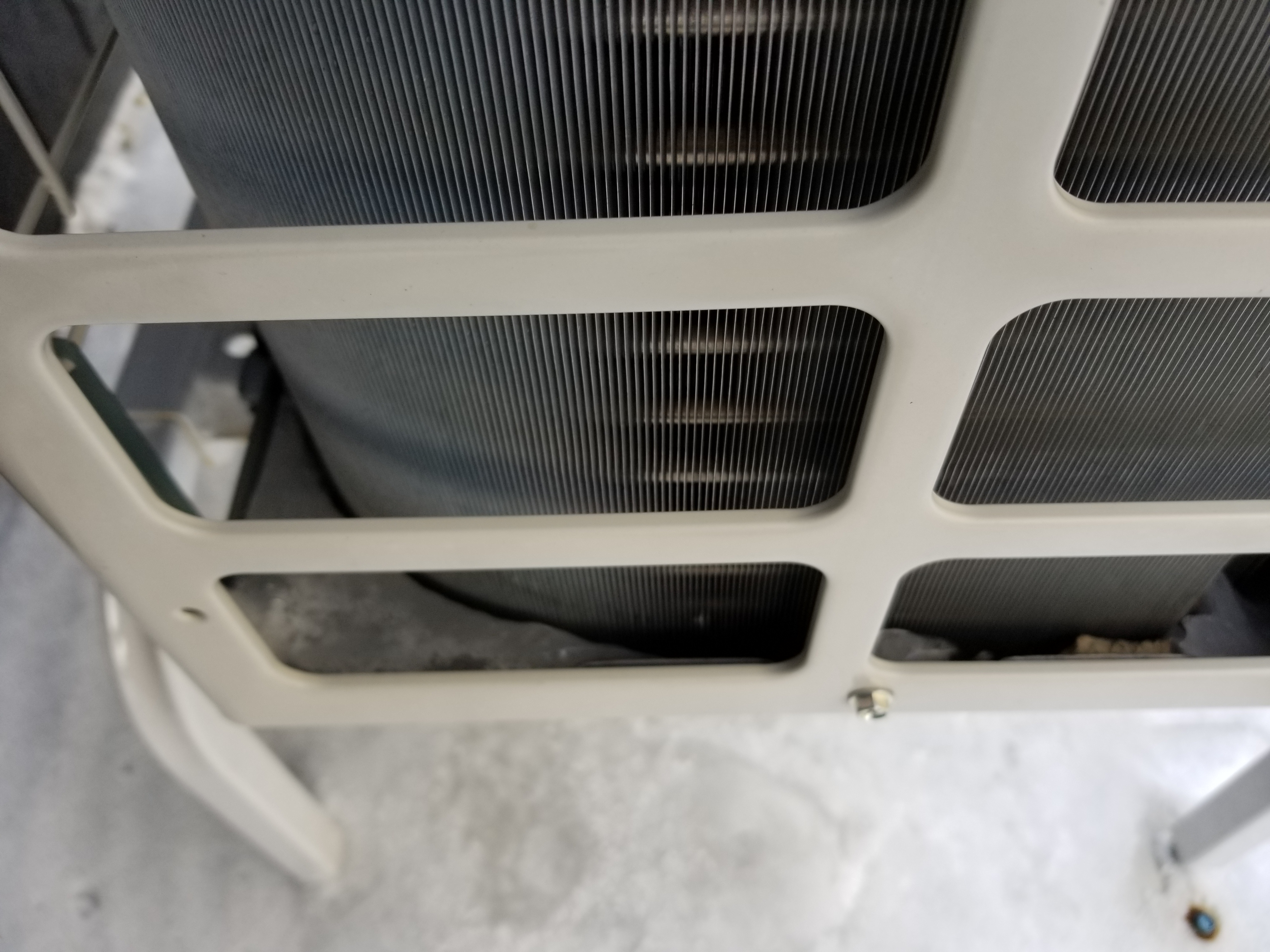
An issue worth considering — especially for those in the design stages of a build — is the added efficiency of a 1:1 set-up for heat pumps, meaning one outdoor condenser for each wall-mounted head indoors (or for each ducted air handler). There appears to be a growing consensus that this layout will offer added efficiency because of improved modulation over what has been a more typical set-up, like ours, which is a multi-zone system that has multiple wall-mounted heads on a single condenser. It’s hard to imagine, at least in our case, that this impact could be more than a few hundred kWh per year, but it’s worth exploring when having someone do a Manual J, S, and D.

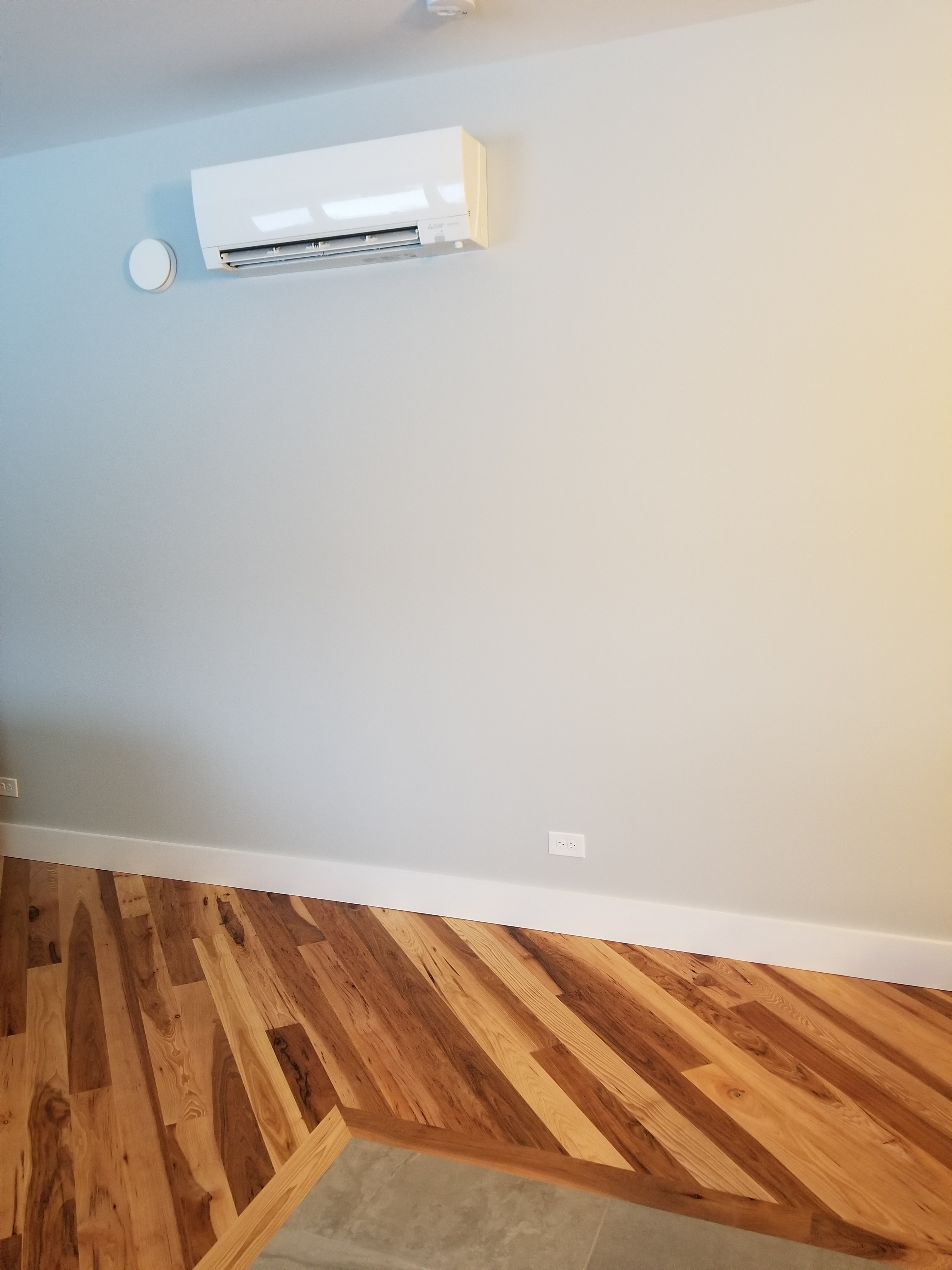
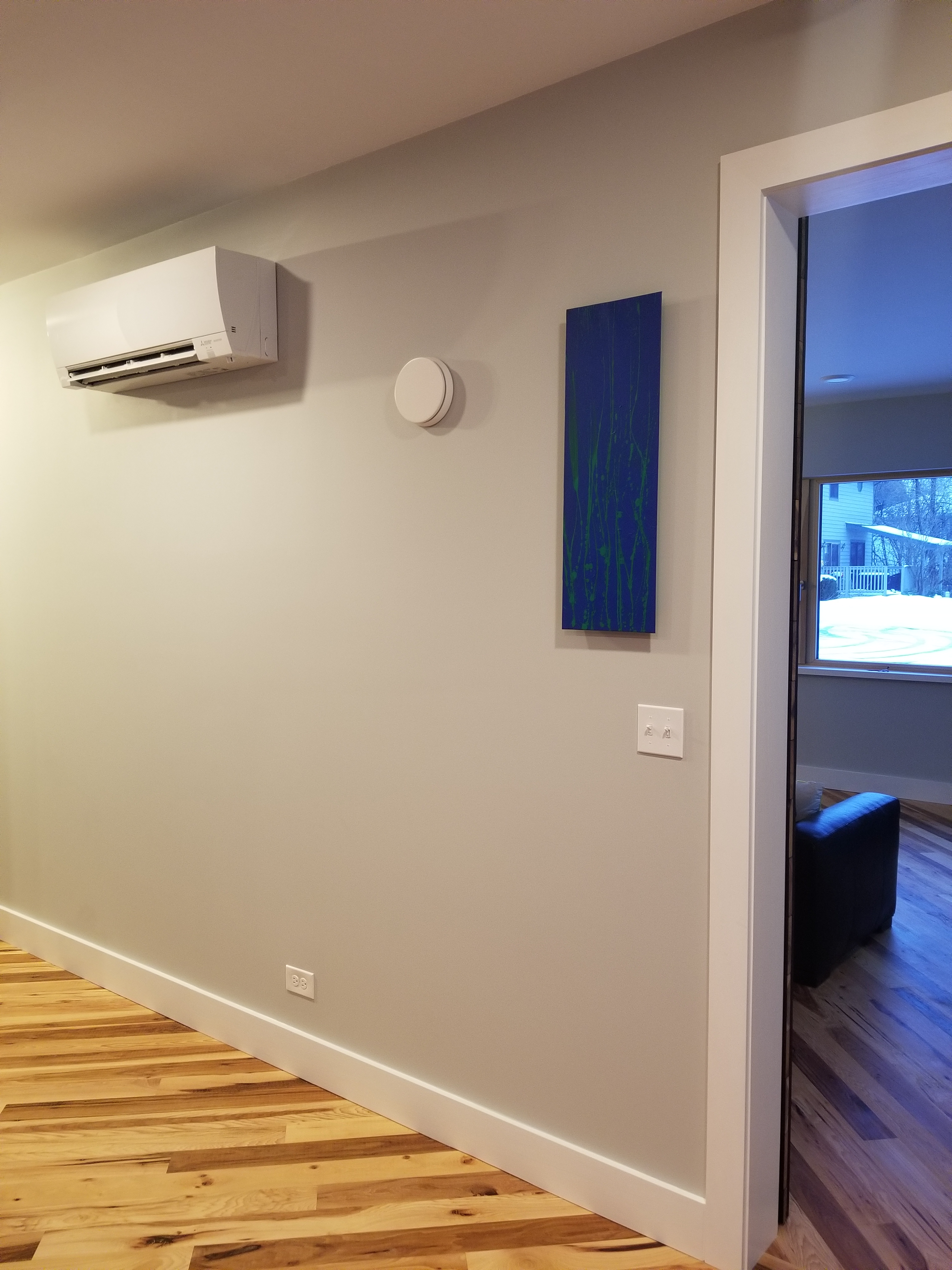
Additionally, we haven’t experienced any issues with the distribution heads in the two bedrooms (9k & 6k Btu’s respectively), either for heating or cooling, although concerns about the effectiveness of these lower Btu units in smaller bedrooms often comes up in discussions on how best to design and layout a heat pump system on Green Building Advisor (the concern is that they’re still too large).

When designing our system, I don’t remember this issue of 1:1 vs. multi-zone heat pump set ups being discussed in any of the information I was able to hunt down, either in Passive House-related books, or even in online resources. I also didn’t come across discussion of the need for active, separate dehumidification while designing our build in 2016. These are just two examples demonstrating that Passive House is still actively evolving as a ‘green’ building program (potential overheating in winter and shoulder seasons would be a third example).

A cautionary tale for designers, as well as building owners, to guard against hubris as the construction drawings develop,a or when the details are finally executed on a construction job site. Other issues may arise with Passive House builds in the coming years, so it’s worth considering potential unintended consequences before finalizing details. Today’s solution may be someone’s costly headache tomorrow.

Additional Solar Panels to Achieve Net Zero?

Based on what we’ve been paying for energy in these first 2.5 years, we don’t feel compelled to add more solar panels at this time. Should the SREC’s dramatically fall in value with a new contract, or disappear altogether, it might encourage us, at that point, to purchase more panels for the roof. But even so, at less than $90 per month, even without the SRECs, it makes our energy bills a relatively painless expenditure (roughly equivalent to one nice restaurant dinner for the three of us, or still less than what we pay on a monthly basis for things like coffee, breakfast cereals, and milk). Put another way, averaging around 3,500 kWh per person of demand, whether with or without the solar panels and our SRECs payments, our monthly energy bill is typically cheaper than a single visit to the grocery store.

Because of the effort and money expended upfront for air sealing and insulation, all while trying to carefully manage window placement and HVAC layout successfully, we’ve managed to whittle our energy costs down to something highly affordable and resistant to significant cost increases. This should remain true, regardless of what’s happening in the market in terms of prices for natural gas, coal, or nuclear power (i.e., the major sources of power in our region, here in the Midwest). Worst case scenario, we add additional solar panels to get to Net Zero or even Net Positive in order to cancel out what remains of our monthly energy bill. This would require an additional 7-8,000 kWh of annual solar production, or roughly 2.5-3 times what our current, relatively small, system produces.

In our specific case as a household — averaging between 3,500-4,000 kWh of solar production per year (this amounts to nearly 40% of our annual demand), combined with SRECs — we nearly end up at Net Zero, at least in terms of total cash spent for energy (arguably the most important — maybe the only — metric that homeowners ultimately care about; whether it’s the total cost to build a new home, or in terms of the annual energy bill). As a result, there’s not much financial incentive to purchase additional solar panels to achieve absolute zero energy consumption (this is in site energy terms only). The fact that this all comes with a house that’s extremely comfortable and quiet to live in, regardless of the season or the room, makes our home only that much more valuable to us.

Passive House + Net Zero?

In addition to designing for Passive House, there is the question of Net Zero or even Net Positive buildings. While Passive House strategies eliminate a significant portion of overall demand by requiring a significant outlay of upfront funds for air sealing and insulation, once this pill has been swallowed, it’s normally cost-effective to incorporate renewable energy of some kind to cancel out the expense of the remaining energy bill.

A quick side note: An excellent resource, one that I found only as our build was coming to an end, is William Maclay’s book The New Net Zero. It contains a wealth of information, but, in particular, many specific construction details vividly illustrated. This is especially valuable for DIY builders, or even seasoned professionals, when evaluating all the possible elements of roof-wall-foundation assemblies.

Also worth noting, if this approach (Passive House + Net Zero) were adopted on a national level, including renovations, it would eliminate a large portion of aggregate energy demand, thus having a meaningful impact on greenhouse gas emissions and global climate change (up to 40% for construction and existing buildings).

Based on what we know at the moment, a combination of approaches — including Passive House building principles, Zero Carbon goals, and the use of renewables — could be the way out of the climate crisis over the long haul. In addition, if adopted as part of building codes, it could mean properly training the next generation of tradespeople (like European-style apprenticeship models, thereby also improving the build quality) while also being a tremendously effective jobs program.

Beyond Net Zero, or even Net Positive, in regards to energy demand, there is increasing awareness about carbon emissions more generally, and the variety of ways to radically reduce or sequester it, including the choice of building materials (for new construction or retrofit projects) or even how we decide to landscape our yards.

Passive House Cost Premium

Unfortunately, due to relatively inexpensive utility rates here in the Midwest, even though Passive House (or Pretty Good House) offers a significant reduction in energy costs if done well, when considered as a percentage of household income the numbers may appear much less impactful or motivating when faced with line items in a build budget for things like air sealing and levels of insulation that far exceed building code requirements.

In our case, the annual energy savings compared to something code-built would likely be in the $2-3,000 range. Fairly significant, but if the purchase price of the home is $500,000 – 1,000,000+ (fairly typical here in the Chicago suburbs for new construction) then even a $100,000 savings over the course of a 30 year mortgage may not convince someone to move beyond conventional construction practices (particularly if they have their heart set on a long list of high-end finishes and appliances). The upfront costs associated with meticulous air sealing and added levels of insulation — if not viewed as an investment in build quality — will likely appear frivolous to the average consumer.

“One of the issues we face here is the fact that energy is cheap, like most things in the Midwest. We don’t have the financial burden placed on us that the coasts do—real estate-wise and energy-wise. So there is not much enthusiasm around green building on a financial level; it’s almost always an ethical issue. The people who are interested want to do a good thing for the environment, as opposed to saving money on their utility bills. Another thing is that people are accustomed to discomfort—we have drastic and frequent temperature swings. It’s really humid in the summer and freezing in the winters, when drafty windows are just accepted. They are used [to] it, so it is hard to sell them on high-performance windows to be more comfortable; or taking measures to keep a basement from being wet—they just aren’t concerned about it. There’s a complacency that we fight against; there’s not enough financial gain to incentivize making upgrades.”

— Travis Brungardt, GBA Q&A

Looking solely at upfront costs is likely to discourage most prospective homebuyers from pursuing Passive House (or even Pretty Good House in many cases), whereas looking at the cost of ownership, including the cost of monthly utilities, produces a more accurate comparison (note, however, this assumes the homeowner can stay put for at least the next twenty to thirty years).

A cost of ownership calculation should also acknowledge less maintenance costs year-to-year since, if the structure is detailed well, it should experience far fewer issues (none ideally), especially damage caused by bulk water intrusion, mold, or even air leakage. Granted, it may take a decade or more before this kind of damage is found in a conventional home, but when it is, it’s rarely (if ever) inexpensive to properly correct.

Hard Choices

As a culture, we have been in a similar place before. One quick example would be automotive engineering applied to car safety. In terms of perspective, if you get the balance between cost and safety wrong when evaluating value, then seat belts, air bags, and better designed bumpers might seem like misspent dollars.

“Nader argued that Detroit willfully neglected advances in auto safety, like roll bars and seat belts, to keep costs down… But using [seatbelts] was strictly voluntary. And many Americans didn’t want to.”

— Daniel Ackerman, ‘Before Facemasks, Americans Went to War over Seat Belts’

In a similar vein, the American consumer has been taught by the market, realtors, and builders to believe cost per square foot is the gold standard of value. As a consequence, little emphasis is placed on building science basics such as air tightness, proper moisture management, thermal performance, or indoor air quality. In layman’s terms, this means the average American home is leaky, parts of it have likely been damaged by bulk water or mold, and it’s uncomfortable in terms of indoor temperatures and humidity, all while delivering subpar air quality to its occupants.

In terms of quality construction and ‘green’ building (Passive House or not), the hard truth is there really is no free lunch (not even renting: rentcafe). Quality, of any kind — finishes, proper moisture management, occupant comfort, even reduced energy bills — has its price, but only those who recognize its value will be willing to pay for it.

Regardless, as homeowners we either pay upfront for the air sealing and insulation, along with high performance HVAC for better IAQ, or we pay monthly (and perpetually) in the form of higher energy bills (this normally comes with less occupant comfort) and far inferior IAQ. Either way, the money is going to be spent, it’s just a question of when (upfront vs. long term month-to-month) and for what (air sealing and insulation vs. mediocre systems and underwhelming outcomes that require costly maintenance over time).

As with car safety in the past, depending on one’s point of view, the answer to these kinds of construction and homeownership options are either obvious or nonsensical. Nevertheless, regardless of the path taken — conventional construction or some version of high performance — no one’s wallet will remain closed for long.

Passive Solar: The Beauty of Light

4

Does Passive Solar Design Still Make Sense?

Our ‘green’ building adventure began in 2013 when I came across various Passive House and high performance projects in Prefabulous + Almost Off the Grid by Sheri Koones. The red house featured on the cover and built by GO Logic, in particular, seemed like a striking departure from conventional homebuilding as practiced in the US.

In its overall shape it echoed an earlier project that I only became aware of later, the Smith House in Illinois by Katrin Klingenberg.

Arguably, in both cases, these homes have too much glass on their south elevations, both in terms of potential overheating of the interior and in purely aesthetic visual terms. Nevertheless, using south-facing glazing to bring in the sun during the winter months while getting some Btu’s of free heat made a lot of sense to us, especially in a heating dominated climate like ours here in the Chicago area.

“…treat the presence of natural light as an essential — not optional — feature of indoor space…”

— Christopher Alexander, et al., A Pattern Language

By the time construction began, we had settled on what seemed like a significant amount of windows and a kitchen door for our south elevation. We felt the layout would be an appropriate amount both in terms of passive solar heating and aesthetics, in addition to daylighting needs.

Moreover, by addressing the main weaknesses of the original Passive Solar movement of the 1970’s, namely the lack of air tightness and sufficient levels of insulation, we hoped that we could strike a balance between enjoying the seasonal movement of the sun in and out of our home while mostly eliminating the risk of overheating, even during shoulder seasons (spring and fall).

Since our build, however, there appears to be growing concern about just how effective this design strategy really is for Passive Houses, or high-performance homes more generally. In effect, are the potential savings on a heating bill really worth the risk of temporarily overheating interior spaces?

Joe Lstiburek, of Building Science Corporation fame, puts it bluntly when quoted in a GBA article regarding the use of high SHGC glass:

“Don’t bother with the passive solar. Your house will overheat in the winter. Yes, you heard that right. Even in Chicago. … You should go with very, very low SHGCs, around 0.2, in your glazing. If this sounds familiar to those of you who are as old as me, it should.

“We were here in the late 1970s when ‘mass and glass’ took on ‘superinsulated.’ Superinsulated won,” Lstiburek continued. “And superinsulated won with lousy windows compared to what we have today. What are you folks thinking? Today’s ‘ultra-efficient’ crushes the old ‘superinsulated,’ and you want to collect solar energy? Leave that to the PV.”

Clearly, he’s not entirely wrong, especially when some of the early failures in the Passive House movement revolved around this very issue of overheating. If you were an early adopter of the Passive House concept, especially if you were the homeowner, and you ended up with comfort issues because of too much glass on your southern facade, it certainly would make you doubt the purported precision of the Passive House energy modeling.

Nevertheless, with careful planning, it is possible to avoid this issue of overheating while still getting to enjoy most of the benefits associated with passive solar design. In our case, this meant limiting windows on the north side (net energy losers) to just our daughter’s bedroom, while glazing on the east side shows up only in a small area of our front door.

Passive House front door
Small amount of glass in our front door offering some daylighting benefit for our entry area.

In addition, we avoided any potential for overheating from our west-facing windows by using self-tinting Suntuitive glass in our master bedroom and family room. This glass can fluctuate in its SHGC between .08 – .18 depending on whether in its fully tinted or clear state (varies depending on surface temperature of the glass).

windows with Suntuitive self-tinting glass
West facade with self-tinting Suntuitive glass.

With the other three sides of the house accounted for, we were able to concentrate all of our attention on the best window layout for the south side of the house. The utility room, which is on the southeast corner of the house, only really needed a small window, so we went with a single 3′ x 5′ unit. In the kitchen, the window above the sink was already going to be limited because of the lower cabinets, and was mainly for a view while doing dishes. This unit ended up being 4′ x 5′. For the kitchen door we went with a mostly glazed door with privacy glass, which has worked out well as it lets in an abundant amount of daylight while it’s never caused any issues with overheating.

“Finding the right position for a window or a door is a subtle matter.”

— Christopher Alexander, et al., A Pattern Language

The real challenge was getting the family room window on the south side of the house sized correctly. The temptation was to go too large since we had the space to do it. Instead, we wanted to retain some empty wall space for artwork on either side of this window, while also remembering that even the best window is still a lousy wall (e.g., R-40 wall vs. R-6 window).

In the end, we decided to go with a 4.5′ x 9′ window in our family room, slightly smaller* than the units on the west facade with Suntuitive.

{*7-27-20 Correction: I messed this up. The dimensions weren’t different between the south-facing family room window and the west-facing windows with Suntuitive — it was a height off the floor change. For the south-facing family room window we went slightly higher, 32″ off the finished floor, in order to gain a little more privacy, while on the west-facing windows we maintained a lower height of 27″ off the finished floor to maximize our views out and into our backyard. This 5″ difference may not sound like much, but it has a dramatic effect in terms of overall views and perspective when standing at these windows.}

In terms of wall area on our south facade, the windows and kitchen door account for just under 15% of the total, so not a crazy amount, and obviously nowhere near the amount of glass in a curtain wall.

The Sun’s Path Month-to-Month

For those who haven’t directly experienced a space that utilizes passive solar design principles, it may be helpful to see in photos what exactly this effect means month-to-month in a real home.

In our case, we have a long interior wall that runs east-west along the longest axis of our home. This wall effectively separates the private areas to the north (bedrooms and bathrooms) from the public areas to the south (family room, kitchen, and utility room). For context, this long wall stands almost 16 feet from all of the south-facing windows.

In our kitchen and family room, here’s what the sun looks like near midday in January:

Passive solar in January
Sun in January, slowly moving away from the back wall (at right) that runs east-west along the longest axis of the house.
passive solar in January
Sun pouring into the utility room in January.

By the middle of February, the sun is already making its way towards the windows, barely able to reach the family room couch, while it still adds plenty of sunshine and warmth to the kitchen and family room areas:

passive solar in february
Sun in mid-February.

By the Spring equinox, the sun has continued its slow march across the family room floor towards the south-facing windows:

passive solar in march
Sun in March.

In the basement, with the help of two large south-facing windows (each 4′ x 4′) and our oversized window wells, the sun is making the same progression as it brightens up the below grade space:

passive solar in basement
Basement in mid-March.

Although we chose to forego any windows on the east side of our house, mainly for privacy and energy loss reasons, the small amount of glass in our front door still allows our entry area to be bathed in beautiful early morning light without contributing a significant amount of heat gain:

sunlight entering through front door glass
East-facing entry area flooded with morning light from the minimal glazing in the front door.

The seasonal path of the sun can also be marked on the exterior by its progress up or down the facade of our south elevation. By mid-March you can see the shadow line formed by our substantial roof overhang beginning to make its way down the siding — at this point, just above the windows and kitchen door. This invisible ‘curtain’ will cover the glass in the windows entirely by the end of June, completely denying the heat of the sun direct entry into the structure.

passive solar overhang in march
South elevation in mid-March. Note the shadow line just above the windows and kitchen door.

Even in April the sun is mostly denied entry; reduced to a sliver of light hitting the wood floor in the family room:

passive solar in april
Family room in April.

In June, by the time of the summer solstice, the sun has been pushed outside completely, limited to the metal sill pans on the exterior of the windows.

window layout for Passive House
Our south elevation during the rough framing stage. Layout from left to right: family room, kitchen door, kitchen window, and utility room.

With significant and thoughtfully placed windows on the south side (combined with a substantial roof overhang), we’re able to enjoy views to the outdoors year-round, allowing us to maintain an unbroken connection to nature in our yard, without any of the heat or glare normally associated with the summer sun. It also means we don’t need to bother with curtains or other window treatments, or the hassle of managing when they should be opened or closed.

Also, since the transition from winter (welcoming the sun in) to summer (denying the sun entry) has proven to be seamless, we’ve been able to avoid installing any curtains or window treatments in order to hide from any periods of unwanted sunlight. Basically, this ‘invisible curtain’ effect of passive solar design means we enjoy all the benefits of window treatments without any of the hassles (routine opening and closing, cleaning, or maintenance and repair), all while maintaining an unobstructed view of the outdoors. This is especially rewarding during the long winter months when starved for sunlight and extra warmth, but equally pleasurable as life begins to hum in the yard with the return of spring and summer.

In the photo below, the family room window (at left) and the kitchen door are protected from the heat of the sun by the roof overhang. The window on the back wall (facing west) is protected by self-tinting Suntuitive glass, which also allows us to enjoy unimpeded views of our backyard without the need for curtains or window treatments, even on the sunniest and hottest days of summer.

passive solar in June
Family room in June with no direct sun allowed entry into the space.

On the exterior, by the middle of June, this shadow ‘curtain’ has fallen over the entire face of the south-facing windows, denying the sun entry into the home where it could cause unpleasant glare and unwanted heat gain (these windows have a SHGC of .54), which would needlessly increase cooling loads for our Mitsubishi heat pump system, while also reducing overall occupant comfort.

Around the summer solstice in June, this is what the set-up looks like outdoors:

overhang for passive solar in summer
Southwest corner of the house around the summer solstice.
overhang blocks summer sun for passive solar
A second view of this ‘curtain’ effect; this time from the southeast corner of the home.

This effect is also visible from the interior while looking out the south-facing windows. With a substantial roof overhang the sun can barely reach the metal sill pans by the middle of June:

overhang protects window sill from summer sun
Utility room window in the middle of June. Note the sun hitting the outside edge of the metal sill pan.

In June, the sun is able to get slightly deeper inside the home in the basement — in this case managing to hit the surface of the window stool or sill.

basement window sill with sun in June

Even in the heart of the summer, the sun is still denied direct access to the interior spaces on the main floor:

passive solar in July
Family room in July. The sun remains outside.

A second look at the metal sill pan from the utility room window, this time in July:

overhang protects window sill from summer sun

After slowly making its way back into the south-facing living areas, by November the sun is once again approaching the back wall in the family room and kitchen:

passive solar in November
Family room by mid-November.

Even though the utility room window is a relatively modest size (3′ x 5′), it provides ample daylight and plenty of warm sunshine over the course of our long winter months:

passive solar lets in the sun in November
Sunlight spilling out of the utility room by mid-November.

Here’s another view of the sun exiting the utility room on its way to the back wall in the main living area:

passive solar lets in the sun in November
Sun in mid-November.

“If the right rooms are facing south, a house is bright and sunny and cheerful; if the wrong rooms are facing south, the house is dark and gloomy. Everyone knows this. But people may forget about it, and get confused by other considerations. The fact is that very few things have so much effect on the feeling inside a room as the sun shining into it. If you want to be sure that your house, or building, and the rooms in it are wonderful, comfortable places, give this pattern its due. Treat it seriously; cling to it tenaciously; insist upon it.”

Christopher Alexander, et al., A Pattern Language
passive solar sun getting into the kitchen in November
Sun hitting the kitchen countertops in November, bathing the space in a warm glow.

By late December, around the winter solstice, the sun is finally able to hit the back wall in the main living area, maximizing the amount of direct sunlight that enters the house:

passive solar design lets in the sun in December during the winter solstice
Sun during the winter solstice, at the doorway to the master bedroom.
passive solar design lets the sun enter deep into the structure in December
In late December, the sun hits the back wall where the family room meets the kitchen.
sun enters deep into the house around the winter solstice
Sunlight from the utility room window hitting the barn door in the main living area.

Even in the basement, where it’s more difficult for the sun to make its way into the space, with our oversized window wells and two large windows the sun manages to get very close to the center of the space just in front of the structural beam. This light pouring in helps keep us connected to the outdoors, mostly eliminating the cave-like feel normally associated with many below grade spaces. Even on the coldest days in winter, this daylighting effect makes the basement a warm, inviting space.

passive solar design lets the sun enter deep into the basement
Sunlight entering the basement in mid-December.

Some Final Thoughts

We were expecting to enjoy the seasonal movement of the sun, watching it progress in and out of the main living space, warming us in the winter while also helping to moderate summertime AC demand. One unanticipated surprise, however, is how effective our window layout has been in maintaining a high level of daylighting, even on the grayest of overcast days.

Short of a menacing thunderstorm that turns the skies gray-black, we almost never have to turn on lights during the day. For instance, in the photo below it has snowed overnight, and the skies are an unrelenting blanket of gray. Nevertheless, because daylight has ample means for entering the living space, no artificial light is necessary. Note, too, in the background, how clear the Suntuitive glass is when not in its fully tinted state.

The kitchen door, because it consists mostly of privacy glass, contributes a great deal to this daylighting effect — both in summer and winter — and we’re extremely happy we didn’t choose a more opaque door style.

Another side benefit in this regard is how the porch light outside this glass-filled door also acts as a de facto night light for the kitchen — its soft, but effective, glow makes it easy to navigate around the space in the middle of the night without having to turn on any interior lights.

passive house window placement improves daylighting even on extremely cloudy days
Even on a cold, gray winter day, the windows welcome in a great deal of daylight, dramatically improving the overall livability of the space, while also allowing us to keep the lights turned off.

One final, unanticipated surprise is how much the house is flooded with light on cloudless nights when there’s a full moon. The moonlight creates a soft, beautiful source of light as it falls across these interior spaces.

In terms of shoulder seasons, when sunlight still has some access to the interior but outdoor temperatures are mild or even occasionally warm, we haven’t really noticed a problem. In spring, if outdoor temps should reach the 70’s during the day it is frankly welcomed with open arms, as we’re starved for warm sunshine at winter’s end. In the fall, if there’s an occasional too warm day, we simply open a couple of windows. So far we’ve never had to turn on the AC in October, for instance.

If there’s any failure in our set-up, it would be the family room couch. From the end of December until the end of January, if it’s a sunny day, regardless of how cold it gets outside, sitting on the couch is uncomfortable, if not impossible. Sitting in shorts and a tank top would be the only way to make it remotely comfortable.

Thankfully, we’re almost never on the couch during this time, so it’s never been a problem for us. Having said that, if this family room were dedicated office space and I needed to be sitting at my desk from 10am-2pm, it would be extremely uncomfortable. This is a good example of how carefully not just an overall floor plan needs to be designed, but how even individual spaces need special attention, in particular for year-round HVAC comfort based on how occupants are actually going to be using the space.

Overall, we’ve been very pleased with the layout of our windows and their ability, in conjunction with the roof overhang to the south, to allow in ample amounts of sunlight during the colder months while still being able to keep it out on the hottest days of the year. With detailed planning, our experience suggests that designing living spaces for a real passive solar benefit is still a worthwhile goal.

Although it may be safer to ignore this design strategy altogether in the hottest climates (simply designing to keep the sun outside year-round may be the better option, which would include the use of low SHGC glass as Lstiburek recommends), passive solar has proven to be a great source of enjoyment for us, particularly during our winters here in Chicago, which tend to release their grip too slowly and ever so begrudgingly.

If given the chance, we would definitely design our house again with these passive solar techniques in mind.

Completing our Wall Assembly: Rockwool Batts, Intello, and Drywall

4

Insulation for Exterior Walls

Once Wojtek and Mark were done installing our continuous insulation on the exterior side of our Zip sheathing (4″ of Rockwool Comfortboard 80), including the first layer of battens (no more errant fasteners through the Zip to worry about), I was able to move inside and begin installing Rockwool Batts (R-23) in our 2×6 wall framing.

Once we had moved on from our first builder, and after reading up on the available options for insulation, we decided to invest in Rockwool insulation, both the rigid Comfortboard 80 on the exterior of our sheathing and the Rockwool batts for inside our stud bays. Although more expensive, particularly the Comfortboard 80 for continuous insulation (used rigid foam would’ve been substantially less expensive), we felt that many of its properties made it worth the added cost.

In particular, by helping our wall assembly to be vapor-permeable (or vapor open), we felt the Rockwool could help mitigate any mistakes, should they be made, in the wall assembly details. This being our first build acting as a GC, we wanted to add some margin for error wherever we could find it.

More details on our wall assembly and how we finalized details, including our desire to maintain a high level of IAQ, can be found here: Wall Assembly

For environmental reasons, one of our goals was to try and be as “foam free” as possible throughout the build. In addition, beyond just this issue regarding the use of foam (in all its forms: rigid board and sprayed varieties alike), there’s increasing awareness about the carbon footprint of our structures, not to mention the total carbon footprint of our daily lives.

At any rate, if I had it to do over, I would at least seriously consider using reclaimed rigid foam for our continuous insulation over the sheathing (both for the potential cost savings and its status as a reclaimed material otherwise headed for a landfill), understanding that it does reduce a wall’s ability to dry to the exterior. As others have noted, using reclaimed rigid foam in this way may be the best, or “greenest”, use of foam insulation until the construction industry hopefully moves beyond its use altogether as better options become more viable (e.g., wood fiber insulation).

Here are some resources for reclaimed rigid foam:

http://insulationdepot.com/

https://www.reuseaction.com/sales/foam/

https://www.greeninsulationgroup.com/

https://www.repurposedmaterialsinc.com/polyiso-insulation/

I would also consider using dense pack cellulose in the 2×6 walls instead of the Rockwool batts if I could find an installer I was reasonably certain could do the work properly. During construction it felt safer to use my own labor to install the Rockwool batts, thus avoiding the possibility of any gaps in the wall insulation. I was hoping to offset the cost of the batts with my free labor, plus I just enjoyed doing the work. Had we gone with the dense pack cellulose, it would’ve been something I couldn’t do on my own (no equipment or training).

lights on in base 4 rockwool
Basement ready for Rockwool batt insulation.

Installing the Rockwool batts is fairly easy and satisfying work. They’re much easier to work with than fiberglass batts, which are horrible on your skin and tend to flop around as you try to get them into place. While the Rockwool also produces some irritating fibers when it’s cut (and requires a dust mask like fiberglass), I found that a shower easily washed them away. Wearing long sleeves during installation also easily mitigates this issue.

base knee wall w: rockwool going in
Insulating the exterior wall in what will be the basement stairwell.

Also, the fact that the Rockwool batts have a friction fit means they don’t require any additional staples or netting to get them to stay put once installed.

Because of the friction fit, it’s also easy to tear off small pieces to stuff into irregular shaped voids should the need arise.

rim joist w: and w:out rockwool
Basement rim joist without and with Rockwool batt insulation.

Like the Comfortboard 80, the batts can have some variation from one piece to another, with a change in the amount of density clearly visible. With the Comfortboard 80, this was significant enough that we avoided using the worst pieces, meaning those with the least amount of density (these pieces felt thinner and sometimes even crumbly). Although this inconsistency was still present in the batts, I managed to use almost every piece, saving the least dense pieces for use in some interior walls for sound attenuation (more on this topic below).

base kneel wall corner rockwool
Corner of basement with knee wall and rim joists insulated with Rockwool batts.

Overall, we were happy with the Rockwool batts, and would definitely use them again should dense pack cellulose not be a viable option. They’re also ideal for a self-build since anyone who’s reasonably handy can install them should they have the time available during construction.

rockwool around base beam
Rockwool batts packed into gaps around the basement steel beam.

In conjunction with the Intello that would eventually be installed over the 2×6 framing members and the Rockwool batts, we also used Flame Tech putty pads to air seal behind every outlet and light switch box. I had seen them used in a Matt Risinger video for sound attenuation:

The other option would’ve been to use airtight junction boxes. Here are a couple of examples: Small Planet Supply and 475HPBS.

In order to limit issues with all the air sealing I was doing, I tried to stick with products my subcontractors already used everyday. As a result, since my electrician wasn’t familiar with airtight junction boxes, I opted instead to come in after he had everything installed and apply the putty pads. I found installing them to be straightforward and pretty quick.

box label putty pads

The putty pads are attached to release paper. Once the paper was removed the pads were easy to mold around each outlet and light switch box.

label putty pad
Acoustical putty pads purchased on Amazon.

Here’s a completed outlet box:

putty pad on outlet
Putty pad molded around every outlet and light switch in exterior walls.

The trickiest area to detail for the walls was at the ceiling and wall junction. In our case, the roof trusses sit on 2-2×6’s turned on their sides, which sit on top of the wall’s double top plate. The 2-2×6’s create space for our service cavity under the bottom chord of the roof trusses.

extoseal-encors-as-gasket
2-2×6’s on edge, sitting on double top plates. Extoseal Encors acting as gasket once taped from the exterior face of the Zip sheathing over the top of the 2-2×6’s, thus completing an air sealed connection between the exterior (Zip sheathing) and the interior before roof trusses are set in place. More details here: Roof Details

Before cellulose could be blown into the attic, we installed Intello to the bottom chord of the roof trusses. At all outside edges the Intello was carried from the roof trusses down over the double top plates of the walls, anticipating the Intello eventually being installed on the walls, which required a connection point between the Intello on the ceiling and the Intello on the walls.

ceiling-wall b4 Intello - Rockwool
Ceiling and wall areas before installing Intello on the bottom chord of the roof trusses and Rockwool batts in the walls.

After the Intello was installed on the ceiling, a service cavity (or service core, or service chase) was created with 2×6’s screwed to the bottom chord of the trusses through the Intello.

string between junction boxes to make sure they're straight
Service cavity with 2×6’s attached to trusses through the Intello. More info on the service cavity here: Ceiling Details.

This gap was going to be a dedicated space for lighting and the 3″ Zehnder tubes of our ERV (as things turned out, we didn’t end up needing this space for the Zehnder tubes).

bare trusses - intello - intello w: single layer CB 80 - service chase
Intello coming down from the roof trusses to cover the double top plates on the wall.

Before installing the Rockwool batts in the walls, I was also able to fill this gap created by the two 2×6’s on their side that sit on top of the double top plates with leftover pieces of Comfortboard 80. The first piece of Rockwool fit snug inside the gap, while the second piece was attached to the first with some plastic cap nails and the friction supplied by the 2×6’s forming the service cavity. Some additional holding power was added at the gable ends by utilizing drywall clips (visible in the photo below):

intello onto top plates
Connecting Intello to top plates with a strip of Tescon Vana tape, creating a clean and solid surface for the eventual Intello on the walls.

The drywall clips were helpful in lending support to drywall anywhere that adding solid blocking would be time consuming or a physical challenge.

nailer for ceiling drywall
These drywall clips worked great in places where the sheetrock needed additional support.

Even though we utilized a 12″ raised heel roof truss, and we had 4″ of Rockwool on the exterior of our Zip sheathing, it was important to fill this gap created by the service cavity to make sure our thermal layer was unbroken around the perimeter of the house (4″ Rockwool on the exterior, 5 1/2″ Rockwool in the stud bays). The outside edge of the roof truss is also the most vulnerable to ice damming, so having the 4″ of Rockwool Comfortboard 80 directly below this area where blown-in cellulose would be installed offers some additional thermal performance to the attic insulation.

Another view of this area where roof truss meets the 2-2×6’s standing on their side, creating a gap between the bottom chord of the roof truss and the top plates on the wall below.

sealed top of wall from inside
Roof truss on 2-2×6’s turned on their sides, which have been sealed with Pro Clima tapes. HF sealant completes the airtight connection between the Zip sheathing and the 2-2×6’s.

If I had it to do over, I would go with a 24″ raised heel truss, as this would offer not only significantly more R-value in this area (for relatively little expense), it would also make any inspection or repairs in this area much easier to deal with.

mbr w: rockwool in walls
Installing Rockwool batts in the walls of the Master Bedroom.

As each piece of Rockwool batt was installed, it was important to keep any butt joints between cut pieces tight together. Also, once each piece was snug inside the stud bay I finished by gently fluffing the outside perimeter edges so the Rockwool sat as flush as possible to the 2×6 studs, thus maximizing their R-value.

mbr rockwool complete
Master Bedroom ready for Intello on the walls before drywall gets installed.
family rm w: rockwool
Family room ready for Intello and then drywall.

Intello

With 4″ of Rockwool Comfortboard 80 on the exterior of our sheathing, the code specifies that we could’ve just used latex paint as our interior vapor retarder (Class III).

Again, to improve our margin for error, I felt like it was worth the added expense and time to install a smart vapor retarder (CertainTeed’s Membrain product would’ve been another alternative) to avoid potential issues with diffusion in the winter.

When I asked a question on GBA about this issue, the consensus seemed to be that the Intello, although technically unnecessary, was a nice bit of insurance.

It also added a final layer to all of the previous air sealing details. With redundant layers of air sealing, even if small areas experience failure over time, there are still other areas to back it up, thus maintaining our overall air tightness for the long term.

intello at frt dr basement
Intello installed in the basement stairwell by the front door.
finishing intello mbr
Intello in Master Bedroom nearly complete.

Sealing the Intello to the subfloor was one of the final air sealing chores of the build. It was deeply gratifying to finally get to this point, especially since drywall and then flooring were up next.

tescon on intello at subfloor
Intello taped to the subfloor with Tescon Vana tape.
intello tvana complete mbr
Intello complete in the Master Bedroom.

Thoughts on Advanced Framing Techniques

If I had it to do over, I would use less framing around windows and doors, along with using pocket headers instead of the more traditional insulated headers we ended up with. Pushing the header to the exterior sheathing would mean being able to insulate the pocket on the interior side with Rockwool or dense pack cellulose, rather than the rigid foam we ended up with (unfortunately, XPS in our case).

family rm w: rockwool
Family room ready for Intello.

Before we had to fire them, the two GC’s we were still working with as framing began were unfamiliar with advanced framing techniques, and they were already struggling to comprehend the many Passive House details in the drawings (not to mention many of the conventional details) so, as I’ve noted elsewhere, I had to pick my battles carefully.

Another change I would make would be at points where interior walls meet up with exterior walls. Rather than using ladder blocking to make the connection, which is still better than more traditional methods (creating a boxed in void that’s virtually impossible to insulate), I would utilize a metal plate at the top of the walls to make a solid connection. In addition to making drywall installation easier since it would create space between the two intersecting walls for sheets of drywall to be passed through, it would also make installing insulation, especially batt insulation, much more straightforward with clear and easy access (no horizontal blocking to get in the way).

intello at ladder
Intello at partition wall that meets the exterior wall (using ladder blocking).

A ProTradeCraft article discusses what builder David Joyce believes is ‘worth doing’ in terms of advanced framing techniques. Perhaps just as important, he points out what he believes can be safely ignored, or is just ‘not worth doing’ when it comes to OVE.

In this Matt Risinger video, architect Steve Baczek delves into some of the key components he uses to optimize advanced framing techniques:

In addition to the pocket headers, the idea of using header hangers instead of additional jack studs, seems to make a lot of sense.

And here’s a ProTradeCraft video regarding their own take on Advanced Framing:

One final change to our framing would be opting for 2-stud corners instead of the California 3-stud corners that we have. Although a relatively small change, I think a 2-stud corner is cleaner and allows for slightly more insulation in this vulnerable area.

Clearly each designer, architect, GC, or framing crew will have their own particular views on advanced framing, so there’s room to make individual choices without undermining the goal of balancing structural integrity with reduced energy demand. Local codes, along with the opinion of your rough framing inspector, will also have to be accounted for.

My guess is these techniques will continue to evolve, especially if specific products come to market to aid the process (i.e. reduce the amount of framing lumber required while ideally also lowering labor costs, all without negatively affecting the overall strength of the structure).

intello kitchen
Intello in the kitchen complete.

One final attempt at some additional air sealing was around outlet and switch boxes as they met up with the Intello. With a bead of HF Sealant, it was easy to make an airtight connection between the Intello and the box.

cu intello at outlet
Completing connections around outlet and switch boxes with HF Sealant.

At doors and windows, I finished these areas off with a strip of Tescon Vana tape, just as I had at the top and bottom of the walls.

intello complete br2
Completing Intello around a bedroom window.

Because corners tend to be problematic in terms of air leakage, I also added a dab of HF Sealant to these areas for the sake of some added redundancy.

lwr lft corn wdw w: intello & tape
Lower left corner of window with some added HF Sealant in the corner.
upper rgt corner wdw w: intello
Upper right corner of a window just before final piece of Tescon Vana tape is run across the top of the window frame, tying together the Intello and the light blue Profil tape that is air sealing around the window.

Sound Attenuation

Since we designed our home with a smaller than average footprint, incorporating many Not So Big House principles (roughly 1500 square feet for the main floor, with another 1500 square feet in the full basement below), one way to make the floorplan feel larger than it actually is was to provide some sound attenuation in key areas (we incorporated several other techniques to “expand” the feel of the floorplan that will be discussed in upcoming posts regarding interior design).

For instance, we installed the Rockwool in the long partition wall that runs east-west down the center of the floorplan. This wall helps define the barrier between public areas (kitchen and family room) on the south side of the home and the private areas (bathrooms and bedrooms) on the north side of the home.

We could’ve used Rockwool Safe ‘n’ Sound, but at the time, during construction in the fall of 2017, it was a special order item in my area, whereas the batts were already in stock, both for my main 2×6 partition wall, a 2×6 plumbing wall, and the remaining 2×4 walls that we felt could benefit from the Rockwool.

In the photo below, the Rockwool in the main east-west partition wall is covering the refrigerant and drain line for one of our three Mitsubishi heat pump heads, along with the usual electrical conduit for outlets and light switches.

rockwool 2nd br entry hall
Rockwool added to some interior walls for sound absorption, thus reducing unwanted sound transmission between certain spaces.

Here’s another view of this partition wall, this time from the opposite side inside the second bedroom:

rockwool 2nd br interior side
Same section of east-west partition wall from inside the second bedroom.

We also added Rockwool to the wall that connects the master bath to the 2nd bedroom bath, and between the 2nd bath and 2nd bedroom. The Rockwool was even added to the wall between our kitchen and utility room, where we have our washer and dryer, in the hopes that it would limit the amount of noise coming from the machines (which it thankfully has).

rockwool bath walls
Rockwool in bathroom wall around main waste stack.

Although this doesn’t make for a totally sound proof connection between spaces (we weren’t prepared to take things that far — roughly equivalent to air sealing a Passive House in the amount of detail required), the ability of the Rockwool to significantly muffle sound between rooms is quite impressive and, for us at least, well worth the effort and added expense.

rockwool kitch - utility
Rockwool in the wall between the kitchen and utility room.

For instance, while standing in the master bathroom, should someone be running water or flushing the toilet in the 2nd bathroom directly on the other side of the wall, the majority of the sound that reaches your ear comes by way of the master bedroom doorway, not through the wall directly. Out of curiosity I tested this idea with music playing on a portable stereo in the 2nd bathroom with the same results — sound through the wall is dramatically muffled, while the same sound that easily travels out of the bathroom and makes it way via the bedroom doorway is crystal clear. With the door to the 2nd bathroom and our master bedroom door closed, this same sound is obviously further reduced.

It’s also nice to watch TV in the family room and know that as long as the volume is at a reasonable level you’re not disturbing anyone trying to sleep or read in the two bedrooms. This kind of sound attenuation also adds a level of privacy to the bathrooms while they’re in use.

And, again, it’s not that no sound is transmitted from one room to another, rather it’s almost entirely limited to doorways, thus significantly reducing the overall impact of the noise that is transmitted. In other words, our goal was rather modest, we were just after significant sound absorption, not sound proofing (e.g. the level of noise cancellation required in a professional recording studio or a high-end home theater room).

As a result, I would definitely use Rockwool for sound absorption again. In fact, I can’t imagine going without this kind of sound attenuation (or something akin to it using other products or techniques outlined in the videos above) now that we’ve been able to enjoy it in our new home. It effectively prevents the issues often associated with so-called “paper thin” walls.

Arguably, addressing this issue of unwanted sound transmission is even more important in Passive Houses or high-performance homes that are already much quieter than conventional homes because of the extensive air sealing and well above code levels of insulation. In our own case, outside noises either disappear entirely or are significantly muffled — this includes a commuter train a couple of blocks away.

As a result, any noises within the home itself become much more pronounced since they don’t have to compete with the typical noises coming from outside the home. For instance, when we first moved in the fridge in the kitchen was easily the most obvious, consistent sound in the house. After a couple of weeks it just became background noise we’ve grown to ignore, but it was surprising just how loud it was initially, especially our first few nights in the home when everything else was so quiet.

In addition to excessive air leakage and obvious temperature swings between rooms, along with poorly sized or placed window layouts, the lack of any sound attenuation between rooms is one of the issues we notice the most when we’re inside more conventionally built homes. Much like all of the conveniences associated with a modern kitchen, it’s easy to take something like effective sound attenuation for granted until you’re required to go without it (e.g. in the case of kitchens while on a camping trip or waiting for a kitchen to be remodeled).

With all of the Rockwool batts in place, and the Intello installed over the exterior walls, drywall could finally go up.

Drywall

We went with USG 5/8″ EcoSmart drywall (GBA article on EcoSmart). We chose the 5/8″ over 1/2″ mainly for added durability and some slight sound deadening between rooms.

I had read about Certainteed’s AirRenew drywall, but it sounded like the only VOC it absorbed was formaldehyde, which, if I understand the issue correctly, can be safely avoided with the use of appropriate cabinets and furniture. If memory serves, AirRenew works by utilizing a compound similar to triclosan, meaning a biocide, which some believe can have potentially serious health effects. It’s not clear to me, even now, whether the use of AirRenew drywall makes sense, or exactly what compound (or series of compounds) are utilized to absorb the formaldehyde since Certainteed has remained silent on this point, claiming the information is proprietary. Nevertheless, it has a Declare label, so ILFI must believe it’s reasonably safe to have on painted ceilings and walls.

At any rate, we wouldn’t be bringing in any new furniture that would have elevated levels of VOC’s (including flame retardants) once construction was complete. Since our last house was significantly larger, roughly 2,800 sq. ft., it was fairly easy to downsize, donating or giving away what we couldn’t use in our new house, while holding on to our favorite and most useful pieces. It also helped that we never really filled up our last house (e.g. we never got around to purchasing a formal dining room set), so we didn’t have as much “stuff” to discard as we might have.

Moreover, by being mindful of every finish we create or use (primers, paints, wood flooring, grout sealer, caulks and sealants, kitchen cabinets etc.), along with any other products we might bring into the new house (e.g. surface cleaners, new furniture, fabrics, even perfumes and colognes, etc.), we’re hoping to maintain a high level of IAQ.

The International Living Future Institutes’s Red List and their database of Declare products were a big help to us, even though we’re not pursuing any kind of certification with them. The Greenguard certified label was also helpful, in particular when it came time to choose tile and grout.

By consciously choosing every product and material that comes into the home, it’s possible to at least reduce our exposure to harmful VOC’s and chemicals. While still imperfect (Who can you trust?), these kinds of programs do allow designers and homeowners to take some control over the environments they’re creating and living in, which is empowering to a degree. Far better if the US regulatory bodies operated under a precautionary principle model when it came to industrial products.

Frankly, in a rational system, one that was truly looking out for the best interests of consumers, this kind of research — time consuming and frustrating busy work to put a finer point on it — would be considered laughable if not horrifying. In a rational system it would be safe to assume that any product for sale, apart from some careful instructions on their use and disposal, would be safe to have inside your home without having to worry about short or long term health implications.

Nevertheless, if unintended health consequences are to be avoided during a renovation or a new construction build, consumers have little choice but to do the necessary homework (or pay someone else to do it for them) and be as thoughtful as possible with their selection of materials.

drywall family rm
Kitchen and family room after drywall was installed. Ready for primer, paint, and flooring.

Now that all of the elements of our wall assembly were complete, it was time to have some fun with final finishes: flooring, wall colors, wood trim, doors, kitchen cabinets…

Blower Door (Air Sealing #9 )

4

When it was time to schedule our blower door test we considered using Eco Achievers, but we only knew about them because they’ve worked extensively on projects for our original builder, Evolutionary Home Builders. We decided the potential awkwardness, or even a possible conflict of interest, wasn’t worth pursuing their services. An example of guilt-by-association I suppose, one that is probably unfounded but, nevertheless, the strong affiliation with our original builder made it difficult for us to reach out to them for help. They also hired one of Brandon’s former employees (this employee was nothing but nice and professional towards us as we were deciding to part ways with Brandon), which would’ve only added another layer of awkwardness to the situation.

Unsure how to proceed, I looked online and found Anthony from Building Energy Experts. He was able to come out and do a blower door test for us, helping me hunt down a couple of small leaks, so that we ended up at 0.34 ACH@50 for this initial test.

Here’s a Hammer and Hand video discussing the use of a blower door:

On a side note: all of the Hammer and Hand videos, along with their Best Practices Manual, were incredibly helpful as we tried to figure out all the Passive House details related to our build. It’s no exaggeration to say that without Hammer and Hand, the Green Building Advisor website, BSC, and 475 HPBS, our build would’ve been impossible to accomplish on our own. I owe an incredible debt of gratitude to all of these great resources who invest valuable time sharing such a wealth of information.

Below is a Hammer and Hand video noting the importance of properly detailing corners to avoid air leaks:

Because of this video, I sealed all of my corners for the windows and doors like this:

HF Sealant in corner of window with Tescon Profil and  Extoseal Encors
Adding Pro Clima HF Sealant after completing taping of the corner, just for added insurance against potential air leakage.

I also added some HF Sealant to the lower portion of the windows, since some air leakage showed up in this area with Anthony where components of the window itself come together in a seam.

HF sealant and Tescon Profil tape around Passive House window
Seam near bottom of window where components meet — sealed with HF Sealant.

The areas where components come together often need special attention.

Tescon Profil tape and HF sealant in corner of Passive House window
Close-up of this same area — seam in components sealed, along with the bottom corner of the window and the gap between window buck and window.

Even with layers of redundancy in place, in the picture below there was a small air leak still present at the bottom plate – sub flooring connection. A coating of HF Sealant easily blocked it.

Once the stud bays were insulated (after most of the siding was up), the interior walls would eventually be covered with Intello (I’ll cover the details in a future post on interior insulation), adding yet another layer of redundancy for mitigating potential air intrusion.

HF sealant at sill plate and subfloor
Area of kitchen sill plate leakage.

Anthony didn’t have any previous experience with a Passive House build, so it occurred to me that it might be beneficial to reach out to Floris from 475 High Performance Building Supply (he had already done our WUFI analysis for us), and Mike Conners from Kenwood Property Development to see if there was someone locally who did. Mike is a Passive House builder in Chicago who had already helped me out with some Rockwool insulation when we came up short earlier in our project (the two GC’s we fired repeatedly struggled with basic math), and he was very nice to take the time to answer some other technical questions for me as well.

Both, as it turned out, ended up recommending that I contact Steve Marchese from the Association for Energy Affordability.

Steve would eventually make three trips to the house, doing an initial blower door test after the structure was weather-tight and all the necessary penetrations had been made through our air barrier, a second test after exterior continuous insulation was installed, and a final test after drywall was up to ensure there hadn’t been any increase in air leakage during the final stages of construction.

starting blower door test for Passive House
Steve setting up the blower door for his first test.

Following Passive House principles for our build, we also followed the same protocols for the blower door tests: Blower Door Protocol

With the structure under pressure from the blower door fan, Steve and I walked around the house while he used a small smoke machine in order to try and find any leaks that I could then seal up.

testing window gasket with smoke
Steve starting at the windows. Here testing a window gasket for air leakage.

The gaskets around our windows and doors proved to be some of the weakest areas in the house although, comparatively speaking, it was inconsequential since the overall air tightness of the structure was fairly robust (favorite word of architects).

using smoke pen to test window gasket
Steve showing me the impact a window in the unlocked position can have on air tightness. The gasket, ordinarily squeezed in the locked position, works to bring the sash and the frame tightly together.
using smoke pen around large window
Looking for areas around the windows that might need adjusting or additional air sealing.

For instance, even though no substantial air leakage showed up around this kitchen door, during our first winter this same door eventually had ice form outside at the upper corner by the hinges, on the exposed surface of the gasket where the door meets the frame.

using smoke pen around kitchen door

After figuring out how to adjust the door hinges, there was no longer any ice showing up this winter, not even during our Polar Vortex event in late January.

Much the same thing occurred around our front door as well, with the same solution — adjusting the hinges to get a tighter fit at the gasket between the door and the frame.

using smoke to test attic hatch
Steve testing the attic hatch for any air leakage.

Steve was nice enough to go around and methodically check all the penetrations in the structure.

Steve testing plumbing vent in kitchen
Steve testing for air leaks around the kitchen plumbing vent and some conduit.
Steve testing for air leaks @ radon stack
Steve testing for air leaks around the radon stack.
smoke test around radon stack
Close-up of radon stack during smoke test.

There was one area in the guest bathroom where the Intello ended up getting slightly wrinkled in a corner during installation. With Tescon Vana and some HF Sealant I was able to address it so nothing, thankfully, showed up during the smoke test.

Steve testing wrinkled area of Intello
Steve testing area of Intello that I inadvertently wrinkled during its installation.

After looking around on the main floor, Steve moved down into the basement.

using smoke pen to test for air leaks around main electrical panel
Checking for leaks at the main electrical panel.
Steve testing for air leaks @ main panel exit point
Checking for leaks at the conduit as it exits the structure.
using smoke pen to test for leaks around sump pit lid
Looking for air leakage around the sump pit lid.

The lids for the sump pit and the ejector pit were eventually sealed with duct seal putty and some Prosoco Air Dam.

Steve testing for air leaks @ ejector pit
Testing the ejector pit for air movement.
using smoke pen around Zehnder comfo pipe penetration
Checking for air leakage around one of the Zehnder ComfoPipes as it exits the structure.
smoke pen test around Mitsubishi heat pump line set
Looking for air leaks around the heat pump refrigerant lines as they exit the structure.
Steve smoke at sump discharge
Checking around the penetration for our sump pump discharge to the outside.

Before the second blower door test, I was able to add some duct seal putty to the lids of the sump and ejector pits.

duct seal around lid of ejector pit
Ejector pit lid with some duct seal putty.

Below is a copy of Steve’s blower door test results, showing the information you can expect to receive with such a report:

Final Blower Door Test Results

For the last two tests Steve used a smaller duct blaster fan in order to try and get a more precise reading for air leakage.

0.2 @ACH50 blower door test result
With Steve just after the initial blower door test was complete.

Steve would be back two more times — once before drywall, and once after drywall — just to ensure we had no loss of air tightness develop in the interim stages of the build (especially after continuous exterior insulation with furring strips were installed).

Here are the final figures noting where we ended up:

0.20 ACH@50 and 106 cfm@50

We are well below Passive House requirements (both PHI and PHIUS), so there was a great sense of relief knowing that all the time and effort put into air sealing had paid off, giving us the tight shell we were looking for. Even so, it was still pretty exciting news, especially for a first build.

And here’s an interesting article by 475 HPBS regarding the debate over how air tightness is calculated for PHI vs. PHIUS projects, and the potential ramifications:

Not Airtight

HVAC Part 2: Ductless Mini Split

9

System Requirements

The plan for our house was to combine an HRV or an ERV (for a continuous supply of fresh air), with a ductless mini split air source heat pump system for our ventilation, heating, and air conditioning needs. Almost all of the projects I had read about utilized this same combination, especially here in the US.

The only real debate, apart from specific brand options, was whether or not to utilize only one distribution head on our main floor, as opposed to installing multiple heads for a more ‘dialed-in’ level of comfort (e.g. in the basement or the bedrooms).

Our original builder had in our construction drawings one head in the kitchen/family room and one in the basement, which was pretty standard for a Passive House level project. It was, therefore, pretty shocking to find out that our second builder (there were two partners) and their HVAC subcontractor were suggesting a system that was grossly oversized for our needs. You can read about the details here: GBA: Oversized System 

This was just one of many ‘red flags’ that convinced us to move on and GC the project ourselves. It’s also a reminder that old habits die hard, meaning even seasoned contractors, in any trade, need to be willing to learn new ideas and techniques if they want to truly be considered professionals and craftsmen — unfortunately, they’re the exception to the rule, at least in our experience.

One of the disappointments associated with our build is, in fact, the disinterest (in some cases even outright hectoring contempt) shown by various tradespeople in our area for ‘green’ building generally. Doubtless, at least a partial explanation for why much of the Midwest seems so far behind in adopting ‘green’ building techniques, especially when it comes to air sealing, insulation, and IAQ beyond code minimum standards. Hopefully this changes significantly in the coming years.

Consequently, I took Steve Knapp’s advice (from the comments section of my question) and contacted Home Energy Partners (their new name: HVAC Design Pros). Isaac responded quickly and eventually did our Manual J, confirming we needed a much smaller system, one that is more consistent with a Passive House project, or even just a high-performance build more generally.

Here are a couple of Matt Risinger videos detailing a mini split set-up that’s fairly typical for a Passive House or a Pretty Good House (GBA article on the 2.0 version).

Once we were on our own, in addition to going with a Zehnder ERV and a Mitsubishi ductless mini split air-source heat pump system, we also pursued the possibility of using a Sanden heat pump water heater.

After seeing it used on a Hammer and Hand project, we thought it was a really interesting piece of cutting edge technology:

Unfortunately, after getting a quote from Greg of Sutor Heating and Cooling, and a poor response from Sanden regarding questions we had about the system (they were unresponsive to emails), we decided to stick with our Zehnder, the Mitsubishi heat pump, and then go with a Rheem heat pump water heater (going with the Rheem saved us just over $6,000 in initial cost). Hopefully, as it becomes more popular in the US, the Sanden can come down significantly in price, or maybe less expensive copycat products will someday show up on the market.

Greg was initially willing to work with us, even though we were technically out of his service area, when the Sanden was involved, but once it was only a ductless mini split he suggested we find a Mitsubishi Diamond installer closer to us, which we understood. He was nothing but professional, taking the time to answer any number of technical questions and offering what proved to be sage advice regarding various details for our system.

In fact, taking Greg’s advice, we contacted a Diamond installer close to us, but unfortunately the first installer we contacted disappeared when we were trying to get him to communicate with our electrician on installation details (an infuriating and painfully common experience when trying to build a new house — especially one with unconventional Passive House details).

Finding our Installer

At this point, we were lucky to find Mike from Compass Heating and Air. He came out to the job site and we walked through the details together. He proved to be knowledgeable, helpful, detail-oriented, and extremely professional. Installing our Mitsubishi ductless mini split system with Mike proved to be one of the easiest portions of our build. We never felt like we had to look over his shoulder, making sure he got details right, or that we had to constantly confirm that he did what he said he was going to do — in fact, it was the opposite: ‘Mike’s on site, so that’s one less thing I have to worry about’.

Compass truck on site
Mike and his crew at the job site to install our Mitsubishi ductless mini split system for heating and air conditioning.

Mike also confirmed what Greg and Isaac also pointed out: comfort issues may develop if we tried to get by with just one distribution head on the main floor.

In fact, looking back through old emails, Greg was nice enough to walk me through some of the options employed by those trying to get by with a single head for an entire floor (sometimes even two floors), including leaving bedroom doors open throughout the day (ideally, even at night), and even the use of Tjernlund room-to-room ventilators.

Again, to his credit, Greg tried to stress how important it was that homeowners have realistic expectations regarding the overall effectiveness of these techniques and options.

He also was at pains to make clear how the work of any competent HVAC installer can be easily undermined by a structure that underperforms. In other words, they can design an appropriately sized HVAC system for a Passive House, but if shortcuts occur during the build and the final blower door number comes in higher than expected, or the budget for insulation gets cut (reducing R-values in the structure), then the system they designed has little chance of working as intended. Based on what he wrote, I’m guessing he has dealt with exactly this outcome in the real world — not fun for him, or the homeowners to be sure.

Consequently, by the time Mike from Compass Heating and Air got involved, we had pretty much already settled on using multiple heads. Although it was nice to hear the same consistent message from Greg, Isaac, and Mike in this regard.

In the end, we decided to delete the head in the basement, instead going with three separate heads on the main floor — the largest in the kitchen/family room, and then the other two would go in our bedrooms.

Here are the specs for our system:

Hyper-Heat Compressor (30,000 Btu)

MSZ-FH15NA  (kitchen/family room)

MSZ-FH06NA  (master bedroom)

MSZ-FH06NA  (2nd BR)

head in mbr w: section of drywall
Master bedroom Mitsubishi head and Zehnder supply, both covered to protect against construction debris.

Having the Zehnder supply diffusers on the same wall and near the head of the Mitsubishi has been working well for us. As far as we can tell, there are no discernible issues with this arrangement. By way of comparison, the Mitsubishi head and Zehnder supply diffuser are on separate walls in my daughter’s bedroom — in effect, they’re pushing air towards the center of the room from walls that are perpendicular to one another — but we still can’t tell any difference in terms of performance, either when heating or cooling.

mbr and family rm erv:heads construction
Facing camera: Family room Zehnder supply diffuser with Mitsubishi head. To far left, and facing MBR: Zehnder supply and lines for MBR Mitsubishi head.

Mike was also really good about communicating the system’s requirements to our electrician and our plumber. It was nice to watch all of them walk through the details together, thereby ensuring there were no problems once it came time to start up the individual heads.

condensate and refrigerant
Components for setting up a ductless mini split: refrigerant lines, electric supply, and a drain for condensate.

Living with a Ductless Mini Split

Having lived with the HVAC system, both the heat pump and ERV, for about a year now, our only real complaint is summer humidity, which I discussed in a previous post here: HVAC (1 of 2): Zehnder ERV

This summer we’re going to try using a dedicated, whole-house dehumidifier, which we think should resolve the issue.

Otherwise, our system has been trouble-free.

In winter, the heads do make some noise, tending to ‘crack’ or ‘pop’, especially when first turning on, or when they come out of defrost mode. Although I’ve read complaints about this online, it’s never really bothered us. I remember how loud our conventional gas-fired furnace was in our last house, especially when it first turned on, so I think it’s important to remember the level of certain sounds in their appropriate context.

Also, this ‘crack’ or ‘pop’ sound is, I suspect, louder than it otherwise would be, say in a conventionally built home, since Passive Houses are known to be significantly quieter because of all the air sealing and, in particular, all of the insulation surrounding the structure.

There’s also a noticeable humming sound when the compressor is going through a defrost cycle (especially noticeable at night when the house is otherwise quiet). The heads also temporarily send out cooler air during this defrost cycle, but the cycle is short enough that it hasn’t posed any real comfort issue for us.

heat pump being installed on pad
Setting up the compressor outside.

Regarding interior noise generally, the same holds true even for our refrigerator in the kitchen. We virtually never noticed the fridge in our last house when it was cycling, but in our Passive House it’s arguably the loudest, most consistent noise in the house, especially at night, or if quietly sitting and reading. Again, it took some getting used to, but not really that big of a deal.

In other words, having blocked out, or at least muffled, most of the noise from outdoors (due to extensive air sealing and extensive insulation), any noise indoors becomes much more noticeable and pronounced. The Rockwool we installed between bedrooms-bathrooms, and the kitchen-utility room for sound attenuation definitely helps in this regard (more on this in a later post).

ext line set fully sealed
Line set for the heat pump system exiting the structure after being air sealed.

Just how quiet is a Passive House? Well, one example would be the train tracks that are just a couple of blocks away: When the windows are closed the noise from a passing train is mostly cancelled out — as opposed to when the windows are open, and the train, in contrast, sounds like it’s thundering through our next door neighbor’s yard.

pvc tied down w: duct seal
Interior view of the line set exiting the house.

As far as extreme cold outdoor temperatures are concerned, the system experienced a real test with our recent Polar Vortex weather. Mike was nice enough to check in with us the day before it started just to remind me that the system could shut down if temperatures fell below -18° F, which is what our local weather forecast was predicting.

In fact, this proved entirely accurate. As temperatures eventually fell to -24° F overnight, the system was, in fact, off for a few hours (the Mitsubishi shuts off to protect itself).

With the Zehnder ERV already set to LOW, and using just a couple of small space heaters (one in each bedroom — roughly equivalent to running 2 hair dryers simultaneously), it was easy to get the interior temperatures back up to 68-70° F in less than an hour (from a measured low of 61° F when we first woke up), at which point we turned off the space heaters.

And it was just under 2 hours before the temperatures rose enough outdoors for the heat pump to turn back on. On the second day, the system again turned off, but the interruption was even shorter this time, so we didn’t even bother to turn on the space heaters.

On both days the sun was shining, which definitely helped as light poured in through our south-facing windows, mainly in the kitchen and family room. Even with no additional heat, either from the heat pump or the two small space heaters, the kitchen remained a comfortable 70° F throughout that first day, regardless of the temperature outside.

In the summer, when we have the AC running, we just set the desired temperature on the remotes and largely forget about the system. The three heads together, even in each individual space, have no problem keeping the house and individual rooms cool enough. In this case, it no doubt helps that we have a substantial overhang on the southern portion of our roof, mostly denying the sun an entry point into the home during the hottest days of the year (and the Suntuitive glass on our west-facing windows takes care of afternoon summer sun).

conduit for heat pump thru zip
Conduit for the heat pump exiting the house and air sealed with Roflex/Tescon Vana tape and gasket.

You can see more detailed info regarding air sealing penetrations through the Zip sheathing here: WRB: Zip Sheathing

refrigerant condensate next to beam
Clean, neat lines for the heat pump.

Single or Multiple Heads?

As far as using a single head to try and heat and cool the entire first floor, in our case about 1500 sq. ft., I can only say that I’m glad we chose to use multiple heads. This really hit home as I was completing interior finishes. For instance, there were times when only the head in the family room/kitchen area was running. When you walked into the bedrooms you could definitely feel the temperature difference since those heads had been turned off (roughly a 5-10° difference). As Greg, Isaac, and Mike — to their credit — were all quick to point out, for some homeowners this temperature swing would be acceptable, even something that could be calmly ignored, while for other homeowners it might well be a heartbreaking and deeply frustrating realization.

Depending on how sensitive someone is to these temperature differences, it could  prove a devastating disappointment if the homeowner is expecting uniform consistency throughout their home. Also, since much of the selling point of Passive House techniques is, in the end, occupant comfort, and not just reduced energy consumption, moving from a comfortable kitchen, for example, to a bedroom that some would find outright chilly, might induce some homeowners to ponder: ‘What was the point of all that air sealing and insulation if I’m still cold in the wintertime and hot in the summer?’ If they hadn’t been warned beforehand, like we were, it would be difficult to argue with their reasoning.

Obviously it’s only our opinion, but if it’s at all possible to fit it into the budget, by all means utilize more than one distribution head. Even if you yourself never feel compelled to turn on any of the other heads in a multi-zone system, a spouse, one of your kids, or a guest probably will want to have the option at some point.

cu beam w: zehnder and hp
Zehnder ComfoTubes and various lines for the heat pump as they enter the basement from the MBR and the family room.

In addition, I would also guess that when going to sell the house multiple heads would be significantly easier to sell to a potential buyer (who wouldn’t appreciate customized HVAC in specific rooms?) rather than trying to prove that a single head is sufficient for an entire home, no matter how small or well-designed. Thoughts worth considering before committing to a specific HVAC system.

north facade w: siding
Compressor with finished charred siding and decorative gravel-cobblestone border.

Also worth noting, utilizing the Q&A section of the Green Building Advisor website is an excellent resource for exploring options before committing to a final HVAC set-up. It’s an excellent way to hear from designers and builders who have experience with multiple ‘green’ projects, not to mention actual homeowners who live in high-performance homes and experience these HVAC systems in the real world, as opposed to just data points put into a proposed energy model (incorrect inputs, along with actual occupant behavior are just two ways a potential system could end up being profoundly inappropriate).

This kind of feedback — before construction begins — is undeniably priceless. In fact, I regret not asking more questions on GBA as they came up during the design and construction phases of our build since it is such a valuable resource of useful information.

compressor in snow
View of the same area after our recent Polar Vortex (snowfall, then below-zero temps).

The one real risk we took with our HVAC set-up was foregoing any direct conditioning in the basement, either heat or AC. In the summer, no matter how high the temperatures outdoors, the basement stays within 5 degrees of the upstairs temperatures and humidity, so no comfort issues in this regard have presented themselves. In the winter, however, the temperature remains in the 59-61° range, with almost identical humidity readings as the main floor.

ice under unit
Some ice build-up, but almost all of it on the concrete pad below, not on the compressor itself.

Most of the time this isn’t a problem for us, since we’re either working out (the slight chill gets you moving and keeps you moving), or else we’re doing arts and crafts projects, or reading on a couch under a blanket. The only time the chill gets annoying is when sitting at the computer for an extended period of time, so we may try using a plug-in space heater in the office next winter (although the challenge will be to find one that’s reasonably energy-efficient while also remaining effective).

little ice build-up
Close-up, showing very little ice present on the compressor itself.

Mitsubishi Wall-mounted Heads: Beauty or Beast

I’ve read that some interior designers, and even some homeowners, have expressed aesthetic concerns about the distribution heads. If you go on design-oriented websites like Houzz you can come across some really strong negative opinions on the topic.

family rm:kitchen hp head and zehnder

For us, they’ve never been a problem. Much like the Suntuitive glass on our west-facing windows, or even a dark or bright color on an interior accent wall, after a few days, like anything else, you just get used to it. I never found them to be ugly in the first place though.

MBR w: hp head and zehnder

I also grew up with hydronic metal baseboards for heat, while in apartments and our first home we had the typical floor supply and wall return grilles for a gas furnace — point being, the details of any HVAC system are never completely absent from any living space. There’s always something that shows up visually and, typically, that needs to be cleaned at some point.

In addition, the Zehnder ERV and the Mitsubishi heat pumps meant we didn’t have to utilize any framed soffits or duct chases (at least in the case of our specific floor plan) in order to hide bulky runs of traditional metal ductwork, typical in most homes when using a normal furnace. Unless designed with great care, these tend to be obtrusive, taking up premium ceiling, wall, or floor space. And if randomly placed simply for the convenience of the HVAC contractor, they can be downright ugly.

In other words, it doesn’t really matter if you’re building conventionally or if you’re building a Passive House, all the details of an HVAC system — whether it’s individual components, or even how these components will be placed inside a structure — should be carefully thought through (again, ideally before construction begins) to address any performance or aesthetic concerns.

Controlling and Adjusting the System

As far as the remote controls for the individual heads, we haven’t had any issues.

heat pump remote closed

For the most part, we set them to either heat or AC (roughly 70° and 75° respectively), and then forget about them.

heat pump remote open

To the extent I’ve looked through the manual, these seem straightforward, but again we haven’t really needed to do much in this regard. And when the weather is pleasant outdoors, we take every opportunity to turn off the system completely and then open windows.

Mike also explained the system could be combined with a Kumo cloud set-up, but we’ve been happy with just the hand-held remotes so far.

Routine Maintenance

And much like with the Zehnder ERV, I try to check the filters for the individual heads at least once a month (more like once a week when I was still doing interior finishes). Just as it takes much longer for the Zehnder filters to get dirty now that construction is over, the same has proven true for the blue filters in the Mitsubishi heads. It seems like about once a month is sufficient to keep up with the dust in the house.

Overall, we’ve been very happy with our HVAC set-up, including the Zehnder ERV and our Mitsubishi ductless mini split. As long as the units don’t have any durability issues, we should be happy with these systems for many years to come.

HVAC Part 1: Zehnder ERV

39

DIY Installation

Building with Passive House principles in mind, we knew that, in addition to maintaining a tight building envelope, and incorporating substantial amounts of insulation around the structure, we also needed to install continuous mechanical ventilation in order to have adequate levels of fresh air, not to mention the ability to expel stale air.

We also needed our system, either an HRV or an ERV, to be highly efficient, meaning it could hold onto some of the heat in the conditioned air even as it introduced fresh and, oftentimes, cold air by means of heat exchange as the two streams of air (fresh and stale) passed by one another inside the main unit (without actually mixing together).

After researching the many options, we ended up going with Zehnder’s ERV, in our case, the ComfoAir 350 (the various Zehnder units are based on overall cfm demand of the structure).

We only considered two other brands for our mechanical ventilation (HRV vs. ERV):

UltimateAire

and

Renewaire

In all the research I did prior to construction, these three brands showed up the most in the projects I read about.

Here’s a good debate on the Green Building Advisor website discussing brand options: ERV Choices

Another interesting option would be the CERV system. Because they’re a smaller, newer company, we didn’t feel comfortable pursuing it, but it does look like a viable option worth considering if building a Passive House or Pretty Good House.

I was also familiar with Panasonic units, but I had always read that they weren’t efficient enough in terms of the heat exchange function (or heat recovery) to seriously consider using it in a Passive House or a Pretty Good House in a predominantly cold climate region like ours, here in the Chicago area.

Our Zehnder ComfoAir 350 is said to be 84% efficient in terms of heat recovery (the same principle applies in summer, only working in reverse, when you’re trying to hold onto cooled, conditioned air). Based on what I read during the design phase, the consensus seemed to be that, although more expensive, the Zehnder has a strong track record of performance and durability.

The Zehnder also came with its own ductwork, which we knew would simplify installation, allowing us to do it ourselves, rather than hire someone else to come in and run more conventional ductwork through the house (conventional ductwork would’ve taken up a lot more space as well). Even though the unit itself was more expensive, we thought we could offset some of the total cost for a ventilation system by installing the Zehnder ourselves, thereby saving some money on labor costs.

As far as the ERV/HRV debate for Northern US states, we decided to opt for the ERV because it was supposed to help us hold onto some humidity in winter months, especially important when most structures in the Chicago area are exceedingly dry for most of the winter (and our winters are long). Although I read repeatedly during the design stage that ERV’s can also help control summer outdoor humidity entering the house, this has not been our experience at all. In fact, the ERV seems pretty useless in this regard (more on this below).

The system quote we received was easy to understand, and Zehnder was nice enough to essentially design the system, both in terms of layout (i.e., where we should put all the supply and exhaust points), along with the quantity, or cfm’s, of air for each point. In the end, after commissioning the unit, the system should be balanced, meaning the unit should be bringing in as much fresh outdoor air as it is expelling stale indoor air.

As far as Zehnder units being DIY friendly in terms of installation, in our opinion, this is highly debatable since the installation manual is far from comprehensive. Our installation manual ended at physically installing the main unit on the wall. Not very helpful.

Without a detailed installation manual showing step-by-step how all the individual pieces fit together, you end up with a pile of what initially seems like random parts.

zehnder pile of parts
Everything we need to install our Zehnder ERV. Most of the smaller components are still in the many cardboard boxes off to the right.

This was incredibly frustrating, especially since Zehnder units are purchased at a premium when compared to other competitive brands, and with the expectation of durability and design precision. It never occurred to me to ask before purchasing the unit for an installation manual, since it seemed a fair assumption that no one would sell a premium product without detailed instructions on how to put it together.

We were only able to proceed because of numerous online videos, googling Zehnder unit photos, and by staring at and experimenting with the various parts to try and figure out how it all was supposed to come together. It was an unnecessary and torturous puzzle that shouldn’t have needed solving, and it wasted hours of my life that I’ll never get back. If you do an internet search and type in: “google review Zehnder America” the experience Sean Hoppes had with his installation wasn’t all that different from ours.

Looking on the current Zehnder website (February, 2019), I can’t find a more detailed set of instructions, either written or in a video format, which is disappointing. This seems like a pretty glaring oversight on Zehnder’s part, and one that should be remedied immediately.

Having lived with the unit for almost a year now, overall we’re happy with its performance, and we feel like we could install one fairly easily now that we’ve gone through the entire process, so it’s a shame we can’t say only nice things about the product simply because the installation manual was so limited or, more to the point, non-existent.

With each video and each photo, it was possible to glean one more crucial nugget of information, which took hours, whereas a detailed written manual or a step-by-step video would’ve made the process straightforward, and by comparison, frustration-free.

The videos below were especially helpful, but, nevertheless, they still leave out quite a bit of pertinent information necessary for any first-time installer (especially regarding all the parts that need to be installed on top of the main unit):

Unless there are no DIYers in Europe installing these units, and this is the expectation Zehnder has for its units both for overseas and here in the US, not having a comprehensive installation manual makes no sense. I’m not sure how even a licensed and competent HVAC installer would fare much better without direct experience installing the units. My guess is they would be searching online for missing info much like we did.

Once we got the main unit installed on the wall, and we figured out how all the parts fit together on top of the unit, by the time we got to installing the small, white 3″ ComfoTubes and the large, gray ComfoPipe, the process became much easier.

main unit attached to basement wall
Mounting the main unit to the basement foundation wall with Tapcon concrete screws.

In regards to the gray ComfoPipe for the main fresh air supply and the main exhaust, both of which pass through the wall assembly, we found it more effective to put individual sections together on the floor, and, once fully connected, we marked the points at which the pipes met with a permanent marker.

marking comfopipe w: sharpie
Marking sections of connected ComfoPipe with a Sharpie while they’re on the floor ensures a tight fit once a connection has been made off the floor.

If you try to piece the tubes together one piece at a time in mid-air it’s much harder to gauge when the pieces are actually tightly put together. With each connection point of pipe clearly marked with a Sharpie, it gives you an obvious goal to shoot for once you have the pipe almost in its final position. More to the point, it’s obvious when sections of pipe get out of alignment, or the connection isn’t nearly tight enough — it’s much more difficult to accurately gauge if only going by “feel” once the sections of ComfoPipe are off the floor.

drilling hole for Zehnder exhaust
Making initial cut in the Zip sheathing.

Using a piece of ComfoPipe, we outlined on the interior side of our Zip sheathing exactly where we wanted the pipe to end up (trying to get as close to center as possible — makes air sealing around any penetration much easier). After a hole was cut with a 3″ hole saw, we cut out the rest of the hole using a jigsaw.

hole in Zip for heat pump pvc
Hole cut and ready for the ComfoPipe.
hole set up for comfopipe
Hole made in our Zip sheathing, ready for the ComfoPipe from outside to make a connection with the section inside.
comfo pipe going thru zip sheathing
Ready to push the ComfoPipe into the house from outside to make the connection inside.
Zehnder chipmunk's back
Chipmunks are back.

Once we started using the Sharpie, it was relatively easy to get all the ComfoPipe installed and air sealed around the Zip sheathing.

comfo pipe thru zip sheathing
Making the connection between inside and outside.
roflex gasket for Zehnder comfo pipe
Adding a Roflex gasket to make air sealing much easier.
tescon vana tape around roflex gasket
ComfoPipe air sealed on the interior side with Roflex gasket and Tescon Vana.
close up comfopipe sealed
Close-up of the ComfoPipe air sealed at the Zip sheathing.
installing comfo pipe next to main unit
Finishing up the last sections of ComfoPipe as they leave the main unit.

Following the directions, we kept the ComfoPipe exit points for supply and exhaust more than 10′ apart outside, where they enter and exit the structure, in order to avoid any possibility of the two air streams mixing, which would undermine the effectiveness of the system.

comfopipe ext sealed and covered
Repeating the same air sealing process on the exterior for the ComfoPipe, adding black garbage bags over the opening with rubber bands to keep out dust, dirt, birds, and any critters that might otherwise try to enter the structure during construction.

On the outside, we made sure to extend the ComfoPipe out farther than we needed, giving us some leeway once insulation and siding were installed over the Zip sheathing. This allowed us to cut the ComfoPipe back to the proper depth before installing the permanent covers supplied by Zehnder.

comfo pipe ext close up sealed
Close-up of ComfoPipe as it exits the structure (before insulation, furring strips, siding, and its final cover).

As far as the white tubing is concerned, we really enjoyed how easy it was to put the 3″ ComfoTubes together.

During the design phase, and even after we brought the Zehnder unit to the job site, we always intended to place the diffusers for supply and exhaust points on ceilings. But after really looking at all the cuts in our ceiling service chase that would be required to make this happen, we decided to opt for placing all of them on walls instead.

It proved to be one of the better decisions we made during construction. Not only did we avoid having to make many cuts in our ceiling structure, which would’ve meant a struggle to appropriately map them out around conduit, ceiling lights, and plumbing vents, it had the added benefit of making it much easier to do ongoing maintenance at the diffusers, mainly checking on and cleaning filters, once we moved in.

Zehnder exhaust filter
Cone shaped filter for exhaust diffusers (bathrooms, kitchen, laundry room, and basement in our case).

In fact, during commissioning, our Zehnder rep told me they have issues with homeowners not keeping their exhaust diffuser filters properly cleaned, effectively undermining the efficiency and overall performance of the units. This is understandable if the diffusers are on ceilings, whether at 8′ or 9′. It would be easy to forget about them, or even if you did remember, one can understand the reluctance to drag out a 6′ step ladder every time they needed to be cleaned. We were also told that placement of the diffusers is extremely flexible — almost anywhere can work (check with Zehnder directly just to make sure your proposed placement will work).

Zehnder filter
Diffuser filter in bathroom after about a month. Once all the construction dust settled down from completing interior finishes, these filters don’t get dirty nearly as quickly as they once did — in other words, this isn’t bad at all.

By keeping them around 7′ off the finished floor, it’s easy for me to check and clean the exhaust diffuser filters on a regular basis (1-2) times a month. I always have 2 sets of filters, so it’s easy to remove the dirty ones, put in clean ones, and then rinse and dry out the dirty ones.

Once we decided to go through walls (both 2×6 and 2×4 framed walls), it was just a matter of deciding where in each wall we wanted the diffusers to be placed, and then cutting the corresponding hole through the wall’s bottom plate and the subfloor — being careful to check, and re-check, in the basement for any floor joists, plumbing, or electric conduit that might be in the way.

For bathrooms we placed the diffusers between showers and toilets, slightly cheating towards the showers to ensure maximum moisture removal.

drilling holes for Zehnder tubes
Apparently cutting the holes through the floor looked like fun since my wife was happy to take over this chore for me. The DeWalt we were using worked great until it crapped out on us a couple of holes short of finishing. We definitely noticed a difference going back to a normal drill and hole saw set-up.

At the unit itself, Zehnder supplied us with blue (fresh air) and red (stale air) tags, to mark each ComfoTube as it leaves or returns to the main unit. This should make any potential maintenance or repair issues in the future easier to resolve, as well as helping to avoid confusion as you set in place each pipe at a diffuser.

installing Zehnder tubes
Attaching the white ComfoTubes to the main unit, carefully labeling each pipe for future reference.
Zehnder tubes
ComfoTubes being installed at the main unit.
Zehnder tubes at manifold
Close-up of the top of the main unit, as ComfoTubes are being installed.
Sydney helping us
Sydney, one of our former Excel students, was nice enough to stop by and help us pull the ComfoTubes from the basement up to the first floor.
OB helping us pull and set-up the tubes
OB was also nice enough to come back to help us push and pull the ComfoTubes into place for the diffusers.
spaghetti
Pulling more tubing than we need up to the first floor. Later it’s cut back to properly fit to the various diffuser boxes.
setting up a port
Putting together a diffuser box.

Since we’re leaving the basement ceiling unfinished, it’s an ideal place to see how all the components come together: ComfoTubes meet at the diffuser box, along with the final cover for the diffuser, in this case for supply air. As you can see in the photo, there’s plenty of room in the metal tube of the diffuser box for deciding exactly where to cut it off in order to establish the finished height for the diffuser cover. In the basement we left them at their full height since there didn’t seem to be much incentive to cut them back.

basement supply diffuser
Basement diffuser box with attached ComfoTubes and final diffuser head (supply in this case).
laundry rm zehnder
Exhaust point in utility room with only one ComfoTube.

All of the diffuser boxes required at least two ComfoTubes, except for the laundry/utility room, which only required one. Using one of the supplied black plastic caps made it easy to block off one of the outlets in the diffuser box. These black caps are also handy when pulling the ComfoTubes around into position since they help to keep out any construction debris.

Zehnder laundry room exhaust port
One outlet in the diffuser box is blocked off for the laundry room since we only required 12cfm for this area (12cfm per opening/ComfoTube).

Our kitchen required the most cfm’s, at 36, so it required a special diffuser box and three ComfoTubes.

Zehnder kitchen exhaust
3-hole diffuser box (36 cfm) for kitchen exhaust.

Again, since we didn’t place it in the ceiling, we put it across the kitchen, basically on a diagonal from the stove. So far we haven’t had any issues with cooking grease or odors, and our range hood (recirculating) seems to be doing its job just as well.

sunlight coming down comfo tubes
Sunlight coming down the ComfoTubes into the basement from the main floor.

Using scrap lumber, we were able to give each diffuser its proper stability in the wall cavities. Although the mounting hardware for each diffuser box seems rather fragile, we managed to avoid any issues.

Applying a bit of hand soap around each opening in a diffuser box made getting a solid fit between the ComfoTube, the black O-ring, and the diffuser box fairly straightforward.

installing Zehnder comfo tubes
Attaching ComfoTubes with black O-rings and sliding clips on the diffuser box.
tubes for octopus in kitchen
ComfoTubes for kitchen exhaust going through the subflooring and into the basement.
Zehnder tube with black 0 ring
Putting the black O-ring on the ComfoTube.

It was also fairly easy to get each ComfoTube exactly where we wanted it. Since they’re so small (at least compared to traditional sheet metal ductwork), the tubes are easy to manipulate and move around, whether over a basement beam, around plumbing, electric, or any other structural component that’s not easily relocated. As long as you don’t need to make a short 90° turn, the tubes are easy to work with, so I imagine they would be ideal for renovation work in older homes.

long shot before tightening comfo tubes
It was fairly easy to put the ComfoTubes exactly where we needed them to go.

With most of the ComfoTubes in place, we just needed to add a couple of walls in the basement before finishing up the last few ComfoTubes.

raising basement wall w: Jesus and Eduardo
Jesus and Eduardo were nice enough to come back to help me put up a couple of basement walls.

Once all the ComfoTubes were installed at all the diffusers and at the main unit in the basement, we were able to pull all the lines tighter for a less messy final installation.

spaghetti comfotubes
Before pulling the tubing tight.

Using 2×4’s, we created a little window for the ComfoTubes to pass through under the floor joists. This structure helped to get the ComfoTubes moving away from the main unit in an orderly way that made it much easier to organize all the tubing once it was all installed:

zehnder installed w: tubes
All the ComfoTubes pulled tight, up by the floor joists, kept in place with some plumbing hangers.

Using plumbing hangers also kept the ComfoTubes under control and organized.

hanger straps for comfo tubes
Straps used to corral the sometimes unwieldy ComfoTubes, which can resemble spaghetti if left unorganized. They also worked well at stabilizing the gray ComfoPipe.

The commissioning of the unit, after drywall was complete, was fairly easy and straightforward, apart from a couple of wiring and electrical issues that had to be dealt with by phone with a Zehnder rep beforehand. And ordering filters from the Zehnder website has also been a straightforward and painless process so far (they’re not cheap, but they do seem to be highly effective).

The only issue we’ve really noticed with the unit is during summer when outdoor humidity levels are high. Since the ERV is constantly running, there’s no way to avoid bringing in some humid air in the summer.

And, unfortunately, it’s enough so that our Mitsubishi heat pump set-up (a future Part 2 of 2 for HVAC details) can’t properly get rid of the excess humidity either, even as it keeps the interior more than adequately cooled. We tried setting the heads to dehumidify, but they just dropped the temperature (almost to 60° F) without budging the humidity in the house very much — the rooms were freezing and clammy. As noted earlier, an ERV just can’t handle elevated levels of humidity in the summer on its own.

By having meters in various areas of the house it’s easy to see when humidity levels become a problem (we’ve been happy with our AcuRite gauges). Last summer our solution was to buy a couple of small dehumidifiers, one for the first floor and one for the basement. They worked, but they also ate up a lot of energy. Setting the Zehnder fan speed to LOW seemed to help somewhat, but not enough to avoid using the dehumidifiers. This summer we’re going to try a stand-alone Ultra-Aire whole-house dehumidifier, which should use less electricity, and it should perform at least as well, if not better, at removing excess humidity.

Having read that anything above 60% indoor humidity can be problematic, especially in tighter, high-performance homes, it was disheartening to see the numbers move towards 70% in early summer. This is what prompted the purchase of the dehumidifiers.

From everything I had read during the design phase regarding Passive House, I knew indoor humidity in the summer could be a slight issue, but having experienced it firsthand, it now seems obvious that incorporating a dedicated dehumidifier in any structure that will see elevated levels of summer humidity, even if it’s only expected to last for just a few weeks, is simply a necessity. Based on what I’ve read recently, it sounds like Passive House designers, who were already doing this for Southern US states, are moving towards doing it in states much farther north. Presumably this would also hold true for anyone designing a Pretty Good House as well.

Granted, 60-70% indoor humidity (or even higher) for a couple of weeks probably won’t ruin any structure, but for us, at least, keeping it in the 50-60% range during the hottest days of summer not only gives us some added peace of mind, regardless of the hit we’ll take in terms of overall energy use, but it’s also an issue of comfort (I grew up in a house without air conditioning and still have vivid memories —all of them bad — of enduring hot and humid summer days and, even worse, long summer nights).

Much like the initial complaints of overheating, due to excessive or improper placement of glazing, especially on southern facades, this issue with excessive humidity seems to be part of the evolution in understanding how Passive Houses, or high-performance homes generally, actually work in real-world conditions. Although the concept has been around since the 1990’s, anyone building to or even just towards the Passive House standard should know they are guinea pigs to some extent, no matter how well established the idea may be in building science terms.

In the winter, we’ve had no issues. When temperatures fall below 20° F, we set the Zehnder to LOW, in the hopes that it will reduce demand on the heat pumps slightly, and it seems to hold onto humidity somewhat when the cold air being introduced would otherwise be excessively dry. Indoor humidity levels have been pretty consistent: above freezing they typically stay around 40%, and when temperatures plummet towards zero or below they’ve still stayed in the 30-35% range. We’ve rarely seen indoor humidity drop below 30%, even on the coldest days, which definitely makes a difference on overall comfort levels. I’ve also noticed that wood flooring and wood trim doesn’t shrink nearly as much as it did in our last, conventionally built home.

Also, even when we experienced record low temperatures last month (January, 2019), hitting -24° F without windchill, the Zehnder kept on running without any issues. As far as we know, it never shut off to try and protect itself from the cold (our mini-split system did, but more on that later). The product literature is somewhat vague, only noting that low temperatures could cause a unit to shut off, but it’s unclear at exactly what temperatures or what combination of other environmental conditions might cause this to happen.

Most people either tape or use sealant on the gray ComfoPipe seams to block air leakage. During our blower door test no air leakage showed up, even with a smoke pen test. Nevertheless, during our recent cold snap some frost was evident on the ComfoPipe seams, so I’ll eventually caulk these seams with Pro Clima’s HF Sealant, since there must be some air leakage, be it ever so minor.

In terms of the boost function, when turned on it pulls from all the exhaust diffusers, not just a particular bathroom or the kitchen. Again, for the kitchen, even if we’ve been roasting garlic or cooking something else that’s equally pungent, by the next morning any cooking smell is usually completely gone. There’s never been any lingering smells emanating from the kitchen.

For the kitchen, when you want to utilize the boost function you just set the ComfoSense wall unit to HIGH (the Zehnder equivalent to a standard wall thermostat). Unlike the bathroom boost switches, which run on a timer (set at the main unit in the basement), when you’re done cooking you have to remember to go back and lower the fan speed, otherwise it just stays on HIGH.

The ComfoSense unit also can display error functions or tell you when filters at the unit need to be cleaned. It also has an AWAY function, meaning you can have minimal fan speed to exchange air while you’re on vacation instead of just unplugging the unit altogether.

Zehnder boost switch
Boost rocker switch in the bathroom.

The boost switch in a bathroom is set to run for 30 minutes on the highest fan speed. So far, this seems to be plenty of time for it to work properly. Unlike a normal bath fan, which tends to be quite loud, even when the Zehnder is in boost mode it’s still incredibly quiet, so guests need to know they only need to press the switch once — it is indeed working.

For the bathrooms, the boost function has been working really well at removing moisture after showers. Nevertheless, in the winter, when temperatures are below 20° F and we decline to use the boost function after showers (again, hoping to hold onto some of the added humidity), the bathroom humidity levels still quickly drop from the 60’s and 70’s back to the mid-30’s in less than an hour (and this is even when the Zehnder fan speed is set to LOW).

We’ve also been happy with the diffusers, in terms of installing/removing them when necessary, but also in terms of their overall look. Whether on more neutral colored walls, or something bolder, they just look nice in our opinion.

Zehnder supply diffuser
Zehnder supply diffuser on a neutral background on the wall.

They’re subtle enough to blend in to the background, but attractive enough so when they are noticed they don’t stand out in a negative way.

Zehnder exhaust diffuser
Utility room with a Zehnder exhaust diffuser on a neutral background — around the corner from the clothes dryer.
Zehnder diffuser on wall with mural
Zehnder supply diffuser on a much bolder background.

As far as changing filters at the unit, or even cleaning the core itself, so far it’s been a trouble-free experience.

Here’s a photo of a supply-side filter after one month of exposure in winter:

Zehnder supply filter
A Zehnder supply-side filter (MERV 13) after 1 month in winter.

During the summer, of course, they look much worse after a month with so much more “stuff” floating around (e.g. pollen, debris from landscaping, insects, etc.). Also unsurprisingly, the exhaust-side filter always takes much longer to get dirty as stale air makes its way out of the structure (it probably helps that we don’t have any cats or dogs).

And since we didn’t need the framed-out HVAC chase in the corner of our Master Bath for all the ComfoTubes that we initially planned to send up into our ceilings, we ended up using this area for some much needed niche shelving for various toiletries and even some towels.

Overall, then, we’ve been extremely happy with our Zehnder ERV unit.

Attic Insulation

2

For high-performance structures relatively high R-values for insulation (at least when compared to current building code requirements) are required from the foundation all the way up to the attic (e.g. Passive House or The Pretty Good House).

After some initial research and product pricing, we knew we were going to predominantly use Roxul (with its recent name change, it’s now known as Rockwool) for our insulation needs. But after realizing blown-in rock wool wasn’t available (at least at the time anyway — presumably this will change in the future), and that batts didn’t make much sense for this application (too costly, and they’re considered more difficult to install properly), we knew we wanted some kind of blown-in insulation. The main options, currently, are fiberglass and cellulose.

Fiberglass vs. Cellulose
Best Attic Insulation

We wanted to avoid foam as much as possible throughout the build, both because of its  environmental impact and the fire risk associated with its use, so we didn’t consider spray foam as a real potential option.

After evaluating blown-in fiberglass and cellulose, we decided that cellulose made the most sense for us.

The next decision was to figure out how much, meaning how many inches did we want to blow into the attic. Our first builder was going to do R-49, which is the current code minimum standard here in Illinois. At the time, even before things went horribly wrong with this builder, this felt like too little. I had read stories about other Passive House projects using significantly more, but many of these were in even colder climates than ours (we’re in climate Zone 5 here in the suburbs of Chicago).

How much do I need?
How much insulation is enough?

We decided that rather than settle on a hard R-value as our goal, we would just do a solid two feet of cellulose since we would be doing the installation of the material ourselves (less out near the 12″ raised heel trusses on the north and south sides of the house). There wasn’t a significantly greater cost in materials to go from an R-49 (just under 15″) to the approximately 24″ we blew into the attic.

After doing a little research, and speaking with a Passive House consultant and a local general contractor who consulted with us on various issues as they arose, the consensus seemed to be that attic insulation was an easy, relatively inexpensive place to sneak in more R-value, which is particularly beneficial in our predominantly cold weather climate (the ceiling/attic is where a significant amount of conditioned air wants to escape in the winter anyway). The blown-in cellulose, like the Rockwool, also has some nice sound deadening qualities as an additional benefit.

How much insulation do you need for Passive House?

The cellulose brand in our local Home Depot is GreenFiber, so that was the product we ended up using. Their product is DIY friendly, even allowing homeowners to rent machines for the actual installation:

We started out with 200 bags delivered to the job site. We assumed we were going to need more (the GreenFiber insulation calculator suggested we would need 250 bags to reach 2′ throughout the attic), but thought it might be easier to estimate a final total once the first 200 bags were installed.

The boys, who helped us with various grunt work chores throughout the project, were nice enough to return and help us bring the bags of insulation indoors the night before we started the installation in the attic. We set up a bucket brigade between the driveway and the kitchen, so it went pretty quickly.

guys w: cellulose
The boys after helping us bring in the first 200 bags of cellulose insulation: Luke, Smitty, Eduardo, my wife Anita, and Ricky.

On the day of installation, getting everything set up and started was fairly straightforward. Apart from a loose hose connection at the machine, which a small strip of Tescon Vana tape rectified, we had no issues with the blower. While my wife fed the bags of cellulose into the blower, I was up in the attic directing it into place.

The first couple of hours were actually kind of fun, but getting a consistent two feet of insulation throughout the attic was time consuming and eventually mind-numbingly boring. The first 12″-18″ weren’t so bad, it was having to wait in each section of the attic for that last foot or so to be blown in place that it began to feel like real drudgery.

cellulose installed looking east
From the attic opening, looking east towards the front of the house.

It also didn’t help that I had a fever and a cold on the day of installation, so being up in the attic surrounded and covered in dust didn’t improve my mood. The process, although very DIY friendly, does require patience and a willingness to cover up — eyes, mouth, and nose — for adequate protection against all the dust floating around.

The day before blowing in the cellulose I went through the attic and marked my goal of 24″ of insulation on various roof trusses so I would have a good visual goal to shoot for. In fact, had I known just how dusty and challenging visibility was going to be during the blowing process, I would have marked every single roof truss at the 24″ level to make the job a little easier.

We didn’t have much in the way in terms of obstacles from various services, other than a few pipe vents for plumbing and radon, along with a small amount of electrical conduit for solar on the roof and a single light in the attic (we kept the majority of all services in our ceiling service core and our walls). This made for a fairly straightforward installation of the cellulose.

cellulose installed looking west
From the attic opening, looking west towards the back of the house.
south east corner w: cellulose
Another view, this time a little further to the right, showing the far northwest corner of the attic.
vents by bench w: cellulose
Cellulose at its full depth around the plumbing vents and radon stack.
cellulose at the attic hatch
Finishing up. The attic access hatch is visible at the bottom of the photo.
bench behind attic hatch opening
The bench next to the attic access opening as we finish up blowing in the cellulose.
building up cellulose around attic chutes
Cellulose hitting the underside of the insulation chutes as it gets blown into place at the edge of the roof by the raised heel trusses.

Thankfully I was able to keep the cellulose out of the insulation chutes, instead slowly piling it up just below each chute. The siding guys already had most of the soffits installed (this was the end of October, 2017 last year), including a channel for air flow for our “vented roof” assembly, so any cellulose that found its way into the chutes and down into the soffits would’ve been a real pain to remove (I’ll have a separate post later about the siding installation, including the many details of our rain screen and 4″ of Rockwool on the exterior side of the Zip sheathing).

The bench next to the attic access hatch ended up working out really well, and I was very thankful it was in place.

lid on bench w: cellulose
Lid of the attic access hatch sitting on its bench next to the attic opening after the installation of the cellulose is nearly complete.

By the end of the first day it was clear we didn’t have enough cellulose to finish the whole attic. We started with 200 bags, but we finished up the second day at just under 300 bags total (288 was the final number of bags installed, so a little more than the 250 recommended by the GreenFiber calculator). What we didn’t use we were able to return to Home Depot for a refund.

how much more cellulose
My wife wondering how many more bags until we’re done — unfortunately the answer was simply ‘more’ as she popped her head up into the attic several times towards the end of the installation.

Apart from the north and south sides of the attic around the raised heel trusses, we had a solid 24″ throughout the attic, in fact, a little more in the center of the attic where it was easiest to pile it up and let it accumulate (closer to 28-30″ in some areas). This probably explains, too, the additional 38 bags we used that exceeded the initial estimate by the GreenFiber calculator.

covered in cellulose
This is where a degree from Michigan gets you. #GoBlue. It was a long day.

On a side note, there was also some concern about the weight of the cellulose on the Intello (our ceiling air barrier), but in the end, even where the cellulose was at its deepest, there was thankfully very little sagging evident in the Intello. Even if it had been worse, the 1×4’s were in place to help support the Intello and the cellulose for the long term (the 1×4’s were spaced roughly 16″ apart between the 2×6’s of the service core).

sag1
Slight sag in the Intello evident after installing the cellulose in the attic.
sag2 closer view
Close-up of the slight sag in the Intello near the west gable end of the house.
sag3 Intello touching 1x4's
Another view of the slight sag in the Intello as it touches the 1×4’s directly below it.

It’s worth keeping in mind that the cellulose will settle a bit, especially during the first few months. This is obviously very important when it comes to establishing what depth you’re initially going to blow in and your expectations about long-term R-value after settling has occurred (something to consider before signing a contract if you’re going to be hiring someone to do the work — both parties should agree and understand what the final R-value will be before the work commences).

I was back up in the attic recently as I finished up painting the master bedroom and closet. Since I already had drop cloths down, I thought I should take what will hopefully be one last look at the attic.

ladder in wic
Ladder under the attic access hatch in the master bedroom closet.

On average, the cellulose looks like it has settled about 2-4 inches below its original depth, depending on where I looked.

settling1
Some of the red horizontal lines at 24″ now clearly visible in some parts of the attic.

Even with this settling, the attic probably still comes in close to R-70 on average —significantly less out at the north and south ends of the roof with the raised heel trusses, but a little more in spots towards the middle of the attic where some red lines are still hidden below the cellulose.

settling2
You can see my red arrow and horizontal line at the 24″ level off to the right.

Just under or over R-70 in the attic is in tune with both the Pretty Good House and Passive House metrics for attic insulation for my climate region (Zone 5 here in the suburbs of Chicago).

While I was up in the attic I also noted that there was no evidence of any water or moisture damage on the OSB roof sheathing, or any indication of wind washing of the cellulose, so the attic seems to be performing as designed, which is a great relief.

Attic Access Hatch (Air Sealing #7 )

0

Our attic is designed mainly to hold our blown-in insulation (a future post will go over the details), as opposed to a place for running HVAC equipment, conduit for electric, or as a potential area for carving out additional storage space.

Nevertheless, in order to have access to our attic for future maintenance or repairs, I installed a well-insulated attic hatch in our master bedroom closet ceiling.

Following Passive House and Pretty Good House principles required trying to protect the thermal envelope, even in this relatively small area, in order to avoid what can be a notorious point of air leakage and heat loss (i.e., the stack effect).

There were two main products I considered using for this:

Battic Door (R-50 / without ladder)

They also have a product that allows for a built-in ladder for easier access to the attic (you won’t need to drag your ladder in from the garage) while also maintaining a high R-value:

Battic Stair Cover

The other product I considered using was from ESS Energy Products:

Energy Guardian Push Up Hatch Cover

We ended up going with the Battic product, which I purchased through the Home Depot website (this saved me a trip to the store since it was delivered to site).

Some other products that I’m aware of include:

475 High Performance Building Supply used to sell a Passive House certified version with a fold-down ladder included, but I don’t currently see it listed on their website:

WIPPRO Klimatec 160

Or this product that also incorporates a ladder is available from Conservation Technology:

Attic Ladder

Because the Energy Guardian hatch is made out of rigid foam, I thought the Battic door was the better choice since it seemed like it would be a little sturdier and more durable. To be honest, once the product arrived and I unpacked it, I realized it was something I, or anyone with basic carpentry skills, could put together themselves (assuming you have the time).

Following the directions, I cut an X in the Intello on the ceiling between two roof trusses (and our 2×6 service core below each truss) in order to establish the opening for the Battic frame.

I folded the cut edges of Intello up into the attic for the two long sides of the Battic frame. For the two shorter sides of the Battic frame it was easier for air sealing to push the Intello down into the living area.

At this point I was able to screw the Battic frame into place.

looking up into battic attic hatch
Battic frame initially installed between roof trusses and 2×6 service core.

Once in place, I used a mix of Contega HF Sealant and Tescon Vana tape to air seal the Intello to the Battic frame.

battic - taped sealed to intello
Air sealing the Intello to the Battic frame (short side between trusses).
tescon vana air sealed battic w: HF behind Intello
Another view of the Intello sealed to the Battic frame.
looking down at air sealed battic from attic
View of the installed Battic frame from the attic.
attic access air sealed - attic side
Air sealing the connections between the Intello, the Battic frame, and the roof trusses in the attic.
air sealed corner of battic
Using HF Sealant to make the connections as air tight as possible.

Once the outside perimeter of the Battic frame had been air sealed to the Intello, the only place left for air infiltration was where the lid would meet the frame of the Battic hatch once it was installed (more on this later when I discuss my first blower door test).

There was some additional framing required, but it was just a couple of “headers” between the roof trusses to add structural integrity to the two shorter sides of the Battic frame.

attic access from below
Battic frame with additional 2×6’s on one of the short sides.

Since we were using a significant amount of blown-in insulation in the attic, it made it necessary to build up the sides of the Battic frame in the attic with some plywood to get the top of the opening above where the insulation would eventually stop.

Here’s another view of the 3 sides of plywood installed:

attic access looking down - directly

The fourth and final side of plywood was installed just prior to blowing in the insulation — in the interim this made getting in and out of the attic much easier.

After a couple of practice attempts, it quickly became apparent that raising and removing the lid once in place, and fighting to get it back down into the master bedroom closet, wasn’t worth the trouble. Instead, I built a small bench in the attic next to the Battic frame so I could push the lid up above the level of blown-in insulation, this way it could have somewhere to safely sit while dealing with any issue in the attic.

bench for attic access lid
Battic lid resting on the bench.

It’s very easy to grab the lid off the bench and bring it back down into position while slowly walking down the ladder in the master bedroom closet to make the final connection/seal.

Although the installation process was fairly straightforward and headache free for the Battic product, if I had it to do over, I think I would have the attic access point on the exterior of the structure, for example, on the gable end of the house in the backyard.

GBA – gable access to attic
Custom Gable Vents
AZdiy

Putting the access point above the air barrier would make meticulously air sealing the entry point for the attic less important, so keeping water out of the attic would be the main goal. An additional plywood buck would’ve been necessary, replicating what I did for our windows and doors (more on this later), but I think it still would’ve been the better option overall.

Putting the attic access on the exterior of the house would also mean avoiding an ugly hole somewhere in our drywalled ceiling. No matter how nicely trimmed out, these attic access points on the interior of a home never look right to me. We’ve tried to hide ours as much as possible by sticking it in our master bedroom closet, which has worked out well, but not having one at all on the interior of the house would make for a cleaner, better solution in my opinion.

If granted a do-over, I would also add a cat walk in the attic through the roof trusses. This would make getting to any point in the attic much easier to navigate. It would also help to avoid disturbing the blown-in insulation too much.

And here’s a photo of the bench in the attic, next to the opening for the Battic attic hatch, after the blown-in insulation was installed:

bench surrounded by cellulose
Bench for the Battic hatch lid.

WRB: Zip Sheathing (Air Sealing #6 )

2

Sealing the Seams and Penetrations in Zip Sheathing

Note: This post will concentrate on the Zip sheathing itself, as it relates to seams and penetrations. I’ll address how I sealed around openings for windows and doors, along with our attic access hatch through the Intello on the ceiling in separate, future blog posts.

We used Zip sheathing as our WRB (weather resistant barrier — sometimes it’s referred to as a water-resistant barrier) based largely on Hammer and Hand projects:

Also, for years I’d seen it used on various jobs featured in Fine Homebuilding Magazine.

As the 7/16″ Zip sheathing went up, I taped most of the seams with Pro Clima’s  3″ Tescon Vana tape (available at 475 HPBS), but also their Contega tape (6″ wide), which I used mainly for outside corners and larger seams in the Zip (mainly where the horizontal seam in the Zip transitioned from the exterior walls of 2×6 framing to the roof trusses — shown in a photo later in this post).

My wife and daughter also cut up the Tescon Vana tape into small pieces in order to cover all the nail and screw holes in the Zip sheathing.

beast and eduardo taping nail holes
The Beast and Eduardo team up to tape the nail and screw holes on the lower sections of Zip sheathing around the house.

The nail holes were initially sealed with HF Sealant, also available from 475 HPBS, thus giving them double coverage — this was discussed earlier, here:

Framing (Air Sealing #2)
north side house garage gap long view
Northeast corner of the house where it meets the garage.

Our decision to use the Zip sheathing was also discussed earlier, here:

Wall Assembly

And here’s a good video discussing the Zip sheathing and its benefits (and its place in the evolution of building science):

If I had it to do over, I think I might be tempted to use 1/2″ exterior grade plywood as my sheathing (there are any number of WRB options these days). This would be sealed on the exterior side with either a liquid membrane, like Prosoco’s Cat 5, or a peel-n-stick tape like Henry’s Blue Skinor even another 475 HPBS product Solitex Mento 1000.

The Zip sheathing works, and the exterior green skin held up nicely during construction, even as it sat exposed for nearly 10 months after we fired our GC’s and struggled to keep the project moving forward. Nevertheless, it is little more than glorified OSB, which comes with certain inherent weaknesses.

Matt Risinger does an excellent job of delineating the cost/benefits of using either OSB or CDX plywood as a sheathing material:

house-garage-gap-for-4%22-roxul
Garage (at left) house (at right) connection. Gap will eventually be filled with 4″ of Roxul Comfortboard 80.
garage-house-gap-2
Closer view of this same garage – house connection. Flashing will cover the bottom of the Zip and then carry over the top of the Roxul that covers the foundation.
north-side-seams-taped
View of the north side of the house as Tescon Vana tape air seals the nail holes and the seams in the Zip sheathing.

View of the West facade with Tescon Vana tape, along with the black Contega tape at larger seams (e.g. where the walls meet the roof trusses) and outside corners.

west side being taped
West facade as taping proceeds.
taping north side before mechanicals : windows
Northwest corner of the house, transitioning from the Tescon Vana to the black Contega tape at the corner.
finishing up seams on west facade
Finishing up some of the final seams in the Zip on the West facade.

Once the Zip was fully installed, it was readily apparent that some of the seams, especially near the base of the first floor where a horizontal seam ran around the entire structure, would need to be tightened up.

Here’s a view looking down on one of these areas where the Zip sheathing did not sit flat against the framing members:

down Zip - out of alignment before 1x4's
Horizontal seam in Zip sheathing refusing to lie flat against the 2×6 framing members.

Using a 1×4 in each stud bay, I was able to pull the seam in the Zip sheathing together. It wasn’t always perfect, but the difference was visibly significant and in most areas well worth the effort.

Placing a 1×4 into position over the seam in the Zip, I would drive a couple of screws towards the exterior.

1x4 in study bay before HF
1×4 used to pull an unruly seam in the Zip sheathing together.
screw thru zip for 1x4 in stud bay
Screw from the interior poking outside as it initially gets the 1×4 in place.

Once securely attached from the interior, I went outside and drove several screws into the Zip, both above and below the seam in the Zip, to pull the seam tight to the 1×4. At that point, I could go back inside and remove the two screws that were driven towards the exterior.

In addition to air sealing the exterior side of the Zip sheathing, I also invested some time in air sealing the interior side of the Zip as well. Below is a long view of several stud bays with 1×4’s installed, but before air sealing gaps around the 1×4’s and lower areas of the stud bays with HF Sealant.

stud bays w: 1x4's, before HF

Long view after applying the HF Sealant:

ceiling walls - HF Sealant

Close-up of the interior side of the Zip sheathing meeting a 2×6 framing member in a stud bay after applying a thick bead of HF Sealant:

thick bead HF sealant in stud bay

Close-up of lower area of a stud bay after air sealing with the HF Sealant (it transitions from a light to darker green as it dries):

stud bay w: 1x4 and HF sealant
1×4 installed and HF sealant applied to all gaps and screw/nail holes in the stud bay.

I held off on using the HF Sealant at the wall sill plate/subfloor connection until just prior to installing the Intello on the walls since this area constantly attracts dirt and debris.

Sealing on the interior side with HF Sealant, even between vertical framing members, means that even if there are any weaknesses in either the Zip sheathing or the Tescon Vana tape at these points, air won’t find an easy way in, since it will be blocked from the interior side as well (there won’t be a difference in air pressure to help the outdoor air make its way indoors).

This kind of redundancy in air sealing should give the house long-term protection against air leaks, thereby aiding the long-term durability of the structure, as well as making it a much more comfortable environment to live in.

interior walls sealed w: HF sealant
Using HF Sealant between vertical framing members.

I also spent some time on the roof trusses, sealing around nails, the top plates of the exterior walls, and the many Zip-framing member connections in what will eventually be the attic.

sitting on roof trusses sealing
Sealing around fasteners and framing in the attic with HF Sealant.

This had less to do with air sealing and more to do with preventing any potential water intrusion since this area is technically above our ceiling air barrier (the Intello), which is detailed here:

Ceiling Details (Air Sealing #4)

Inventory of Penetrations through the Zip Air Barrier

I made a mock wall assembly before construction began, which I discussed here:

Wall Assembly

This proved helpful when explaining to the various subs how to help me protect the air barrier — especially when it came time to drill holes through the Zip sheathing. Of particular importance was making holes closer to the center of a stud bay, as opposed to hugging a corner or side of one of the 2×6 framing members. A hole cut too close to a stud or a roof truss is much harder to properly air seal.

bad-good-mock-wall-assembly-for-penetrations
Interior side of our mock wall assembly showing how all penetrations through the Zip should be in the middle of our framing members. Our original plumber was the only trade that managed to screw this up (it’s no coincidence that he was also the only sub that we had to fire).

In effect, any time a sub had to make a penetration through the air barrier we discussed the details, and once the cut was made I immediately air sealed the penetration both on the exterior and interior side.

By sealing each hole in the Zip on both sides, again I hope it ensures the long-term durability of the overall structure. The main argument for this strategy assumes the exterior side of the sheathing will face more extreme temperatures, and fluctuations in humidity, and presumably even wind-drive rain if/when it gets past the siding and 4″ of Roxul insulation, putting it at greater risk of failure (especially in the long term). By taking the time to air seal the interior side, it just gives the overall air barrier, and therefore the structure, a better chance at avoiding air and water intrusion (that’s the goal anyway).

For air sealing I used a mix of tapes, HF sealant (later even some Prosoco products), EPDM Roflex gaskets, and duct seal.

The penetrations for electric service were my first go at using the Roflex gaskets:

John & Donny installing meter
John and Danny installing the electric meter.

The smaller diameter Roflex gasket comes with its own Tescon Vana tape, which makes installation straightforward.

close up meter thru Zip w: TVana gaskets
Electric meter with Tescon Vana – Roflex gaskets installed.
meter - hole, t. vana prior to appl.

Exterior view of electric Meter air sealed with gaskets and Tescon Vana tape:

electric meter close up gasket : t. vana

Once sealed on the exterior side, I went inside to seal the penetrations for a second time:

meter to panel - interior
Air sealing the electric meter on the interior side.

It was a big moment when the electric panel went in:

main panel in - progress
The house is ready for power.

The installation of our solar panels required air sealing two penetrations — one through the Intello on the ceiling on the inside of the structure, along with one exterior penetration through the Zip:

Details regarding the installation of our Solar array can be found here:

Solar on the Roof
corrected solar on:off
Solar disconnect (on/off) with its Tescon Vana gasket.

We also had two frost-free hose bibs, or sill cocks, installed, which also required gaskets on the exterior and interior sides of the Zip sheathing.

hosebib w: gasket
Frost free hose bib with gasket.

One of the big advantages a Roflex gasket has over using a sealant like the green HF Sealant, or Prosoco’s Joint and Seam, is the pipe can be moved in and out even after air sealing, which is especially helpful for installing siding later.

We left the sill cocks loose (unconnected to water supply line inside the house), allowing the siding guys to adjust in and out for a more precise fit of the charred cedar siding.

Below is an example of what conduit through the Zip sheathing looks like before it gets a gasket and some tape:

exterior light conduit before gasket
Penetration for conduit before gasket.

And here’s the conduit after the gasket and some tape:

gasket for exterior light
Conduit after gasket.

Note the extended length of the conduit, anticipating our 4″ of Roxul covering the Zip, 2-layers of furring strips (vertical then horizontal — for vertically oriented siding), and the eventual charred cedar siding.

The photo below shows the penetrations, along with multiple lines of conduit, for our eventual ductless mini-split Mitsubishi heat pump system. The empty hole will be our disconnect for the heat pump. I’ll go into the details of our ductless mini-split system in a future post.

conduit for heat pumps
Penetrations for our Mitsubishi heat pump system.

Same series of conduit pipes after gaskets and being connected to the compressor outside:

heat pump electric w: t. vana before disconnect

In addition to the conduit for electrical hook-up, the Mitsubishi heat pump system required a separate penetration for running the refrigerant lines to the compressor:

hole in Zip for heat pump pvc
Hole cut for the heat pump refrigerant lines.

After discussing it with Mike from Compass Heating and Air, who did our ductless mini-split installation, we decided to use a 4″ section of PVC plumbing pipe as our “conduit” for running the refrigerant lines from the interior of the structure to the outside:

heat pump - pvc pipe in hole for lines
4″ PVC plumbing pipe for the refrigerant lines.

After the PVC was passed through the hole in the Zip, we added a 2×4 underneath it to give it some added stability, along with the usual gasket and tape for air sealing around the PVC pipe:

heat pump - int side - pvc, gasket, 2x4
Before applying Tescon Vana around the Roflex gasket.

Once the refrigerant lines were passed through the PVC pipe, it was clear that some additional air sealing was required.

gaps around pvc lines before duct seal
PVC pipe with refrigerant lines installed.

I filled the gaps around the refrigerant lines from the interior and exterior sides with duct seal. Before stuffing in the duct seal at either end of the PVC pipe, I added bits of Roxul Comfortboard 80 into the pipe to try and give added R-value to the interior of the PVC pipe (hoping to prevent any possible condensation from forming inside the pipe).

duct seal label
A real lifesaver when it comes to air sealing. Readily available at big box stores, or online at Amazon.

Duct seal proved especially helpful at air sealing multiple weak points in the structure —areas that would’ve been difficult or impossible to air seal with just tape, gaskets, or sealants:

heat pump pvc w: duct seal close up interior
Using duct seal to block off air from the interior side.
heat pump pvc w: gasket before t. vana close up
Another view of the PVC pipe with duct seal.
heat pump refrigerant lines - int. leaving basement
The refrigerant lines transitioning from the basement ceiling to the PVC pipe before leaving the structure.

Once the interior was taken care of, I was able to address the exterior side of the PVC pipe:

heat pump lines before tape after duct seal
Exterior view of the PVC pipe with heat pump refrigerant lines exiting the structure. Air sealed with a Roflex gasket and duct seal inside the pipe.

Again, note that the PVC pipe is extended out in preparation for the layers of exterior insulation, furring strips, and siding:

heat pump lines leaving house - sealed
Same area after completing the air sealing with Tescon Vana tape.

And here’s a view of the same area after the siding was installed (I’ll go into the many details regarding the installation of the exterior insulation, furring strips, and siding in a future post):

Heat pump lines w: duct seal and siding
Air sealing for the refrigerant lines complete after the siding is installed.

Additional areas where the duct seal proved to be invaluable:

close up exterior outlet box w: duct seal
Exterior electrical boxes for lights and outlets.

Conduit for the water meter in the basement (only the interior is shown below, but the conduit was air sealed with duct seal on the exterior end as well):

And here’s the same conduit for the water meter as it leaves the house on the first floor:

conduit for water meter sealed w: tape:gasket
Conduit for the water meter, air sealed on both sides of the Zip with the Roflex/Tescon Vana gasket.

I also had to address the disconnect boxes for our solar array and our heat pump. For instance, here’s our solar disconnect box when it’s open:

solar disconnect before removing

And here it is after removing the pull out switch, revealing an air leak:

solar disconnect before duct seal

Close-up of the conduit:

close up solar disconnect before duct seal

An even closer look:

close up penetration in solar box before duct seal

And here it is after being air sealed with the duct seal:

close up solar box after duct seal

I did the same air sealing for the Mitsubishi heat pump disconnect box:

heat pump box before removing

Close-up of the conduit sealed with the duct seal:

close up penetration in heat pump box w: duct seal

During my initial blower door test (more on that later), some air movement around the main panel in the basement was detected, so when the electrician came back we added duct seal to the main pipe entering the house (it had already been sealed from the exterior side with duct seal):

main panel - interior - duct seal
Close-up view of the main panel from the interior where lines first enter the structure.

Besides the penetrations in the Zip sheathing, there were other penetrations through the Intello (our air barrier on the ceiling) that had to be addressed as well. These areas were air sealed with the same set of products as the Zip.

For example, in addition to the conduit for solar through the Intello, we also had to air seal conduit for electric service to the attic (for a light and switch in the attic), in addition to the the penetrations for radon and plumbing waste vents, some of which are shown below:

plumbing vent thru Intello gasket:t. vana
Plumbing waste vent going into the attic.

Another view of this vent pipe after air sealing, this time from below:

sealed plumbing vent from below

Here is one of the vents that our first, incompetent plumber installed too close to one of the 2×6’s used to establish our service core:

plumbing vent installed too close to 2x6
Installed this close to framing makes air sealing the vent needlessly complicated and frustrating.

Here’s the same area after applying the Tescon Vana tape:

plumbing vent too close to 2x6 sealed w: tape

Below is another vent pipe incorrectly installed too close to a 2×6. This one was even more challenging to air seal properly. After the gasket and Tescon Vana, I added the green HF sealant as insurance against air leaks, both for now and in the future.

vent too close w: sealant too

We also had to air seal the penetrations for our Zehnder Comfo-Air 350 ERV ventilation unit. I’ll go into the details of the actual installation later, but here are some photos of the penetrations through the Zip sheathing and how we addressed making them air tight:

ext - comfo pipe going thru zip into basement
First section of Comfo pipe going through the Zip sheathing.
Zehnder tube exiting w: gasket
The gray Zehnder Comfo pipe (for supply air stream) exiting the structure with a Roflex gasket.
Zehnder pipe sealed w: gasket and tape
Closer view of the Comfo pipe air sealed with a gasket and Tescon Vana tape.
close up Zehnder Comfo Pipe w: gasket and t. vana
An even closer view of this same area where pipe meets gasket and tape.

We followed the same process — Roflex gasket and Tescon Vana tape — for the exterior side of the Zehnder Comfo pipe:

ext Zehnder gasket : t. vana
Zehnder Comfo pipe installed, air sealed, and ready for commissioning.

And here’s a picture of both supply and exhaust pipes for the Zehnder:

Zehnder exhaust and supply pipes ext fully sealed
Supply pipe in the background, exhaust in the foreground. The garbage bags keep out weather and animals until after the siding is up and the permanent covers can be installed.

During my initial blower door test some air movement around the sump pit was detected.

sump pit air sealed
Sump pit lid sealed with duct seal, Roflex gasket with Tescon Vana, and the seam between the pit and lid sealed with Prosoco Air Dam.

The sump pump discharge pipe also needed to be air sealed on both sides of the Zip:

sump discharge pipe w: gasket and joint and seam
Sump discharge pipe sealed first with Prosoco Joint and Seam, then a Roflex gasket, before applying Tescon Vana tape around the gasket.

Some air movement around the ejector pit was also detected, so I used duct seal to try and block it.

ejector pit air sealed with duct seal
Ejector pit air sealed with duct seal.

For low voltage — in our case, a cable TV/Internet connection — we found a utility box at Lowe’s (also available at Home Depot and Amazon), and combined it with conduit to transition from the exterior to the interior. The diameter of the conduit is large enough to allow wires for other utilities/services to pass through as well, if necessary, in the future.

cable box
Cable box installed after the siding went up.

An engineer from Comcast-Xfinity visited the site back in the summer, and he gave me the go-ahead for using this box/conduit set-up:

close up exterior of closed cable box
Closer view of the cable box.
cable box ext without cover
The cable wire exiting the house through the conduit, which is air sealed with duct seal.
cable wire int. basement
Cable wire on the interior of the house exiting through the Roxul insulation and Zip sheathing via the conduit and then air sealed from the interior with duct seal.

Even the wire for the doorbell was sealed with a gasket and tape:

doorbell gasket and tape
When the weather warmed up I was able to experiment with the Prosoco R-Guard series of products (note the 3/4″ plywood door buck treated with Joint and Seam and Fast Flash). I’ll go into that more when I discuss prepping for the windows and doors later.
close up of doorbell gasket
A closer view of the doorbell gasket.

Air sealing the penetrations was challenging at times, but also a lot of fun — always keeping in mind the goal of meeting the Passive House standard of 0.6 ACH@50 for our blower door test.

Convinced of the connection between air tightness and the durability of a structure — not to mention the impact air tightness has on heating and cooling loads (i.e. monthly utility bills) —I wanted to see just how air tight I could get the house.

Hopefully this inventory of penetrations will prove helpful to someone in the planning stages of their own “air tight” build. It always helps seeing how other people do things — in particular, the strategies they employ and the specific products they use.

Seeing these real world examples of air sealing around the many penetrations in a structure will hopefully give others the confidence to come up with their own plan of attack for building an airtight structure.

Basement Slab (Air Sealing #5)

2

The Bottom of our Thermal Envelope

Following Passive House principles, we knew we were going to insulate and air seal our basement slab. As explained on the Passipedia website:

“The most important principle for energy efficient construction is a continuous insulating envelope all around the building… which minimises heat losses like a warm coat. In addition to the insulating envelope, there should also be an airtight layer… as most insulation materials are not airtight. Independently of the construction, materials or building technology, one rule is always applicable: both insulation and airtight layers need to be continuous.”

airtightness_with_logo
Illustration courtesy of: passipedia.org

The illustration above also shows the “red pen test”, which is supposed to occur in the design phase of a project, when it’s much easier to address weaknesses or errors in the details of a design — not necessarily just for air sealing, it’s also effective when looking for points of potential water intrusion (e.g., this GBA article), or even to test the thermal layer for areas of thermal bridging. The basic idea is that if your layers aren’t continuous you’ll find yourself lifting your red pen, meaning it’s an area that needs to be addressed.

An effective way of thinking about a structure, utilized by high-performance builders, is to think in terms of 6 sides rather than just 4 when contemplating the details for air sealing and insulating: 4 walls, the attic/roof, and the basement (or frost-protected slab).

A similar approach to Passive House for building high-performance structures is adopted by advocates of The Pretty Good House concept, even if it’s less stringent, more open to interpretation, and tends to be more “rule of thumb” rather than energy model driven (e.g. PHPP or WUFI).

Based on our climate region, which is Zone 5, we decided we wanted to shoot for 16/20/40/60 for insulation R-values — the series of numbers represent R-values for under the basement slab/ the exterior foundation walls/ framed exterior walls/ and the attic (our attic R-value proved to be significantly higher than 60, but more on that later) — which is in the ballpark for both PGH and Passive House (here’s an excellent overall summary of the PH concept I recently came across: EcoCor).

Arguably, the “sweet spot” for how much insulation makes sense for these areas, even when adjusted for climate region, is still a topic for heated debate. Nevertheless, it’s important to keep in mind that the more simple the form your structure takes — for example, 2-story cubes without basements —

the easier it is to achieve Passive House, or similar building standards, since it simplifies framing, air sealing, and limits the exterior surface area in ways that a single story ranch that is spread out and has all kinds of nooks and crannies does not (the difference also has serious ramifications for overall heating and cooling demand). Likewise, simple forms also make it easier to figure out how much insulation you need to reach a benchmark like Passive House or PGH. A simple form can also have durability implications.

Our R-values were based on a number of considerations: the construction drawings of our original builder, information made available by Hammer and Hand (in particular their Madrona House project), and articles on the Building Science Corporation (in particular: 1 and 2) and Green Building Advisor websites. These resources, all of which have proven to be indispensable at every stage of the build, have made our project possible.

In terms of the details around the slab and the foundation walls, this article from the DOE also proved to be especially helpful: Foundation Handbook

2-04_no-cap
Illustration courtesy of: foundation handbook.ornl.gov

After considering various insulation choices (Wall Assembly), we decided to go with Roxul for under our slab, the exterior of our foundation, and our wall assembly (blown-in cellulose in the attic was the only significant deviation from the use of Roxul).

Here’s how the basement slab portion of our project progressed:

Roxul Comfortboard 80 (2″ + 2″)

To get to an R-value of 16 we used two layers of 2″ thick Roxul Comfortboard 80 (R-4 per inch).

We installed each layer with staggered seams, although the Roxul representative I spoke with via email insisted that because the Roxul is so dimensionally stable this isn’t nearly as important as it would be with rigid foam insulation (the same holds true with a double layer of Comfortboard 80 on the exterior side of wall sheathing).

roxul in basement 2 layers
Putting down the 2 layers of Roxul Comfortboard 80 with help from the concrete guys.
roxul long view two layers
The second layer of Roxul being installed.
roxul before stego
Installing the Roxul around the rough-in bathroom pipes, sump, and ejector pits.

One of the many benefits of using Roxul is that the material wants to stick to itself, whether in batt or rigid board form. This makes for tighter joints between pieces, and even when cuts around obstructions are less than perfect it’s easy to fill in any gaps with torn apart pieces of Roxul (again, this holds true for both Comfortboard 80 and their version of batt insulation).

roxul stuffed in around basement pole
Stuffing bits of Roxul around the base of one of the steel columns.

Close-up of the Roxul installed around the roughed-in bath PVC pipes.

roxul around rough-in bath

Another view of the 2-layers, mostly installed:

roxul before stego - facing ladder

A Roxul rep told me to take into account a loss of R-1 due to the compressive pressure of the poured concrete, thus our R-16 for two layers of Roxul is, according to Roxul, really an R-15. Having installed the two layers myself, walked on it during and after installing the vapor barrier (see below), my guess is in some areas this loss in R-value is even greater than R-1.

Based on the comments quoted in a GBA article (Sub-Slab Mineral Wool), I would have to say my experience was exactly the same: in some areas the Roxul seemed to lose most, if not all, of its rigidity. I’ve also noticed while working with both the Comfortboard 80 and their batts that there seems to be a variation in the material from one piece to another and even bag to bag. Some pieces are very easy to cut (these pieces are noticeably stiffer), while other pieces seem “mushier” or lacking in rigidity — either under or over-cooked perhaps — making them more difficult to cut and work with. This seems like less of an issue for vertical applications (i.e. walls), while potentially troublesome for horizontal applications under a slab — especially if you’re depending on that R-4 per inch to meet the demands of energy modeling for a certification program like Passive House.

I’m glad we’ve been able to mostly avoid foam insulation in the build, but seeing the Roxul in a real world application does make me wonder if some kind of rigid foam might’ve given me a more consistent whole floor R-value. Going with a denser version of Roxul would’ve been another, more expensive, option as well (Comfortboard 110).

Stego Wrap

Once the two layers of Roxul were down, it was time to install the vapor barrier over the insulation. While the Roxul acts like a blanket, helping to maintain a consistent temperature in the basement, the vapor barrier helps to keep moisture and soil gases (mainly Radon as I understand it), at bay.

The product I’ve seen used in most Passive House, Pretty Good House, or equivalent projects, is Stego Wrap. Here are two videos detailing its installation and its benefits:

Another product I came across while researching options was Perminator.

Here’s a video detailing the use of the product:

In my area — the suburbs of Chicago — the closest supplier of Stego Wrap was HD Supply.

starting stego around roug-in pipes
Starting around the rough-in bathroom pipes.

We used the 10 mil version of the Stego Wrap. The material is very durable and fairly hard to damage. Even when tears occurred, it was easy to patch with pieces of the Stego red tape, or a combination of a cut piece of Stego Wrap with pieces of the red tape.

stego going down
Stego Wrap carried up the wall and taped to keep it in place during the pour.

Installing the two layers of Roxul on the basement floor was pretty straightforward, while installing the Stego Wrap was generally a pain in the ass. Maybe I was just tired, but I really didn’t enjoy installing it at all. For example, it was difficult to keep it tight to the walls, although I learned to leave it hanging fairly loose at floor-wall junctions, which definitely helped. Getting the first row straight, flat, and smooth was time consuming, and annoying, but it did make getting successive rows installed straight much easier.

jesus helping me w: first row stego
Jesus helping me install the first row of Stego Wrap.
almost halfway w: stego wrap
Making progress with the Stego Wrap.
sealed basement pipe close up before pour
Stego Wrap wth red Stego tape and a Roflex gasket from 475 HPBS.

The pipes after air sealing with EPDM gaskets and red Stego tape:

sealed basement pipes with overlapping Stego

Once all the Stego was in place, we added a 1/2″ of rigid foam insulation at the floor-wall junction as a thermal break. I wanted to use Roxul Comfortboard 80 (their 1.25″ thick version) even for this, but time (Comfortboard 80 is still a special order item in my area, meaning it’s always about 2 weeks away from the time you place your order — hopefully this changes in the near future) and money made the foam an easier choice.

stego w: foam close up

We kept the foam in place by running a bead of OSI sealant on the back of each section before pushing it up against the Stego Wrap. For the most part this seemed to work well.

stego w: foam at slab edge
Roxul, Stego Wrap, and foam installed.

Here’s a close-up of everything installed in a corner:

stego w: foam at a corner

One of the real disappointments of installing the basement slab was seeing the concrete guys put down the welded wire mesh (typically noted as W.W.M. on construction drawings) — basically chicken wire with pointy ends (I exaggerate, but not by much).

If I could do it over again, I would look into using a concrete mix containing sufficient pieces of fiberglass, or some other alternative, so that using the welded wire mesh could be avoided altogether.

I was already familiar with the idea of fiberglass used in place of metal rebar in concrete forms, having experimented with decorative concrete last year and having seen videos like these:

I’m not sure why I didn’t think to ask for fiber reinforced concrete instead of the normal welded wire mesh — it was one detail that just got missed, unfortunately.

As the wire mesh went down, the guys could see how annoyed and concerned I was by the holes it was making in the Stego Wrap that one of them, Oscar, started helping me bend the pointy ends up. Once they were safely pointed up, I went around with the red tape to patch the many tiny holes in the Stego Wrap. Not a fun way to kill a couple of hours.

Why my architect or the concrete guys didn’t suggest a mix with fiberglass instead of the welded wire mesh is unclear. The reality with any green build, especially if you’re acting as GC, is you’re likely to be the only one who really cares about getting the many details right, especially if the architect and subcontractors have never built like this before — they were just doing what they always do.

A couple shots of the basement floor with the welded wire mesh in place:

A closer view with all the elements in place prior to the pour:

corner of basement pre-pour

Concrete

Here’s various shots of the slab itself being poured:

hole in floor for basement slab
It was necessary to cut a hole in the subfloor just inside the front door in order to get the concrete into the basement.
concrete going thru floor
long view of brace for pour
The guys starting at the back of the basement.
leveling back corner of basement
back corner of basement pour #2
One corner complete.
pour heading towards basement stairwell
leveling towards stairwell
pour at stairwell
Tools at stairwell
finishing concrete at stairwell
troweling at stairwell
Enrique completing the trowel finish.
cement truck kissing corner of garage
Side of the garage kissed by the cement truck.
close sewer clean out
Close.
close long view sewer
Really close.

Slab Edge

Once the slab was in place, I wasn’t quite sure how to deal with the edge along the perimeter. As usual when I get stuck on some detail, I asked a question on GBA:

How do I seal…
Stego Wrap and Foam cut away from slab edge
Cutting away the excess Stego Wrap and pink foam.
close up of slab edge
Close-up of the wall-slab junction after cutting everything down flush with the floor.

Using the Prosoco Air Dam seemed like the best, and most straightforward, option. In addition, after considering various ways to cover this gap after the Air Dam was down between the wall and floor, and after priming and painting the basement walls, I realized the gap visually disappears for the most part, and really wasn’t worth thinking about.

wall-slab connection after air dam.jpg
Junction between wall and slab after using Air Dam and priming and painting the wall.
close up of wall - slab conection after air dam
Close-up of Air Dam after primer and paint, at the wall-slab connection.
another view slab:wall connection
Another view of the slab – wall connection.

By not putting anything down to cover this gap, if the basement ever does experience water damage, it’s one less thing to remove and replace.