Our attic is designed mainly to hold our blown-in insulation (a future post will go over the details), as opposed to a place for running HVAC equipment, conduit for electric, or as a potential area for carving out additional storage space.
Nevertheless, in order to have access to our attic for future maintenance or repairs, I installed a well-insulated attic hatch in our master bedroom closet ceiling.
Following Passive House and Pretty Good House principles required trying to protect the thermal envelope, even in this relatively small area, in order to avoid what can be a notorious point of air leakage and heat loss (i.e., the stack effect).
There were two main products I considered using for this:
They also have a product that allows for a built-in ladder for easier access to the attic (you won’t need to drag your ladder in from the garage) while also maintaining a high R-value:
We ended up going with the Battic product, which I purchased through the Home Depot website (this saved me a trip to the store since it was delivered to site).
Some other products that I’m aware of include:
475 High Performance Building Supply used to sell a Passive House certified version with a fold-down ladder included, but I don’t currently see it listed on their website:
Because the Energy Guardian hatch is made out of rigid foam, I thought the Battic door was the better choice since it seemed like it would be a little sturdier and more durable. To be honest, once the product arrived and I unpacked it, I realized it was something I, or anyone with basic carpentry skills, could put together themselves (assuming you have the time).
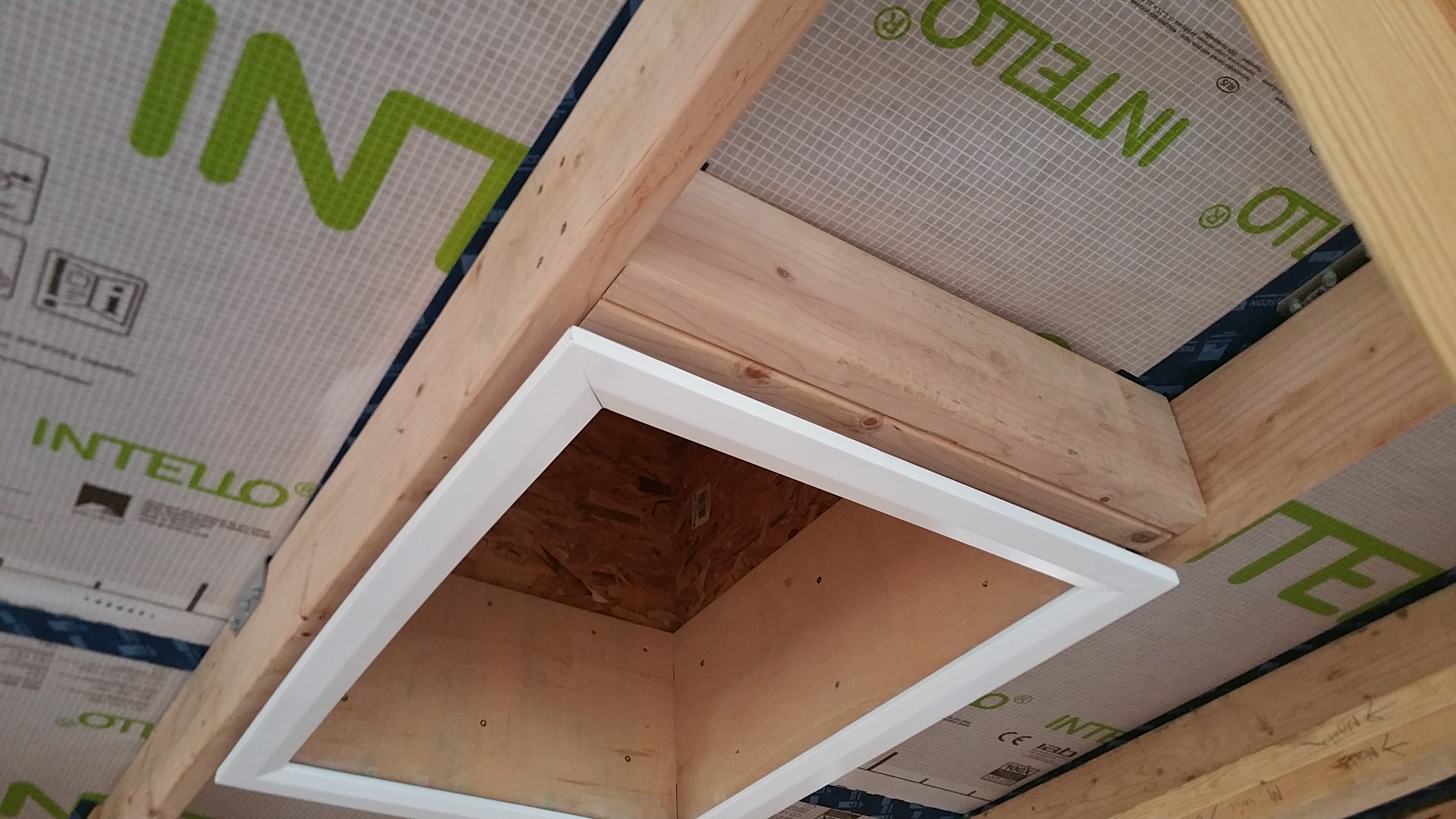
Following the directions, I cut an X in the Intello on the ceiling between two roof trusses (and our 2×6 service core below each truss) in order to establish the opening for the Battic frame.
I folded the cut edges of Intello up into the attic for the two long sides of the Battic frame. For the two shorter sides of the Battic frame it was easier for air sealing to push the Intello down into the living area.
At this point I was able to screw the Battic frame into place.
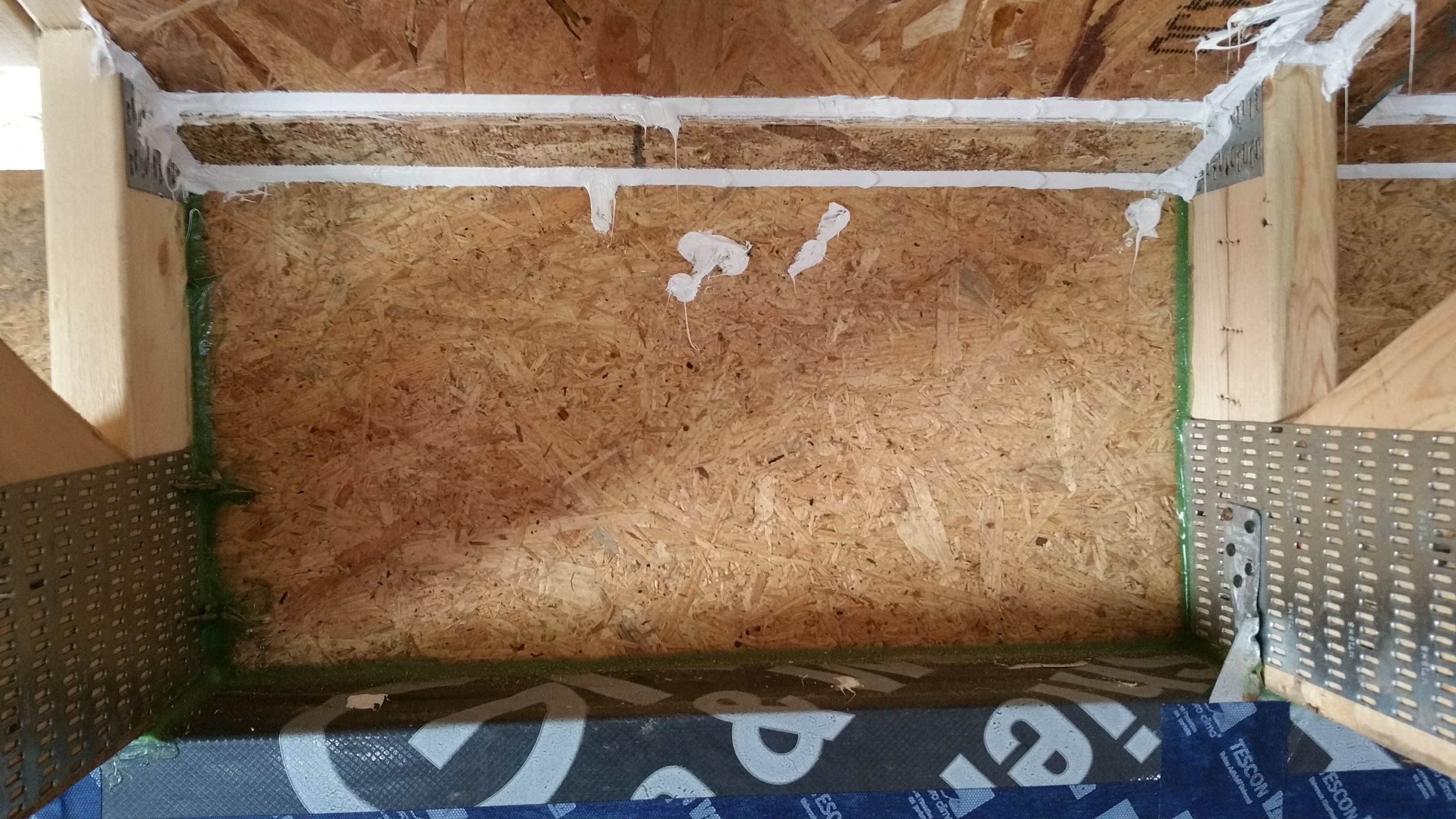
Battic frame initially installed between roof trusses and 2×6 service core.
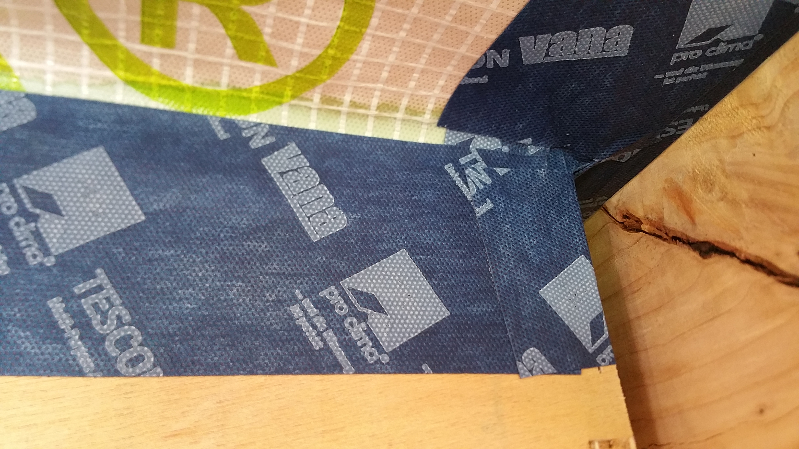
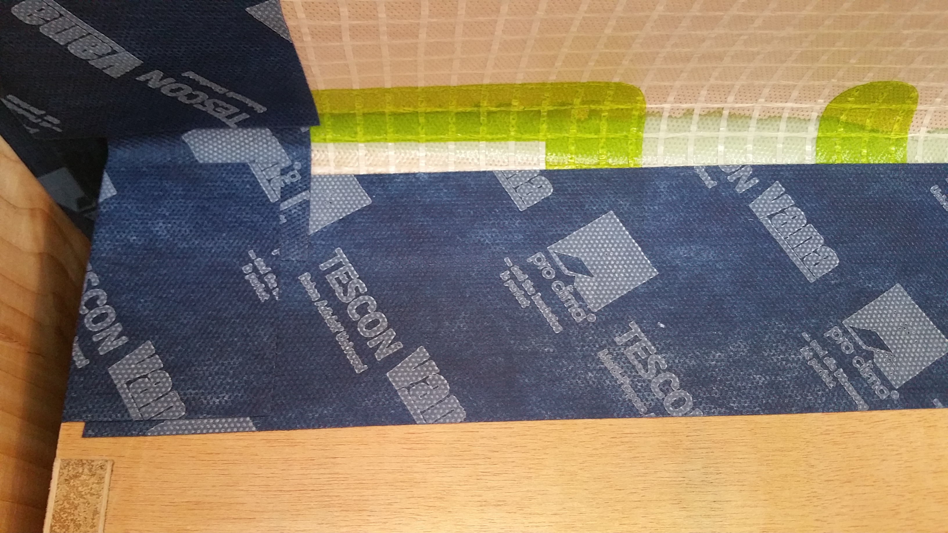
Air sealing the Intello to the Battic frame (short side between trusses).
Another view of the Intello sealed to the Battic frame.
View of the installed Battic frame from the attic.
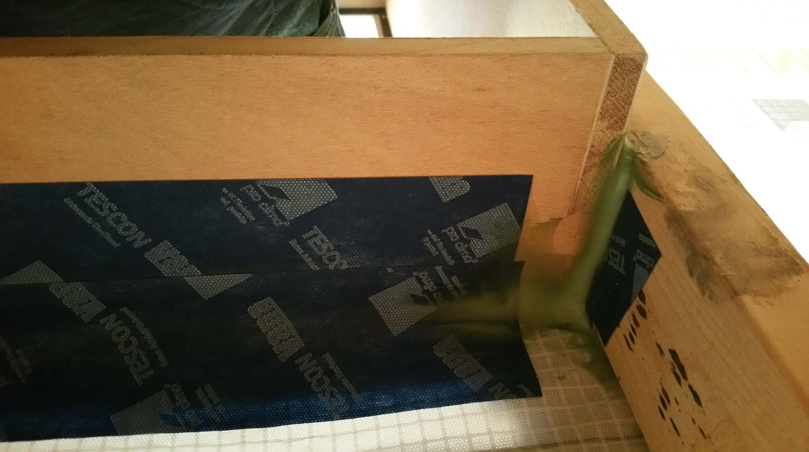
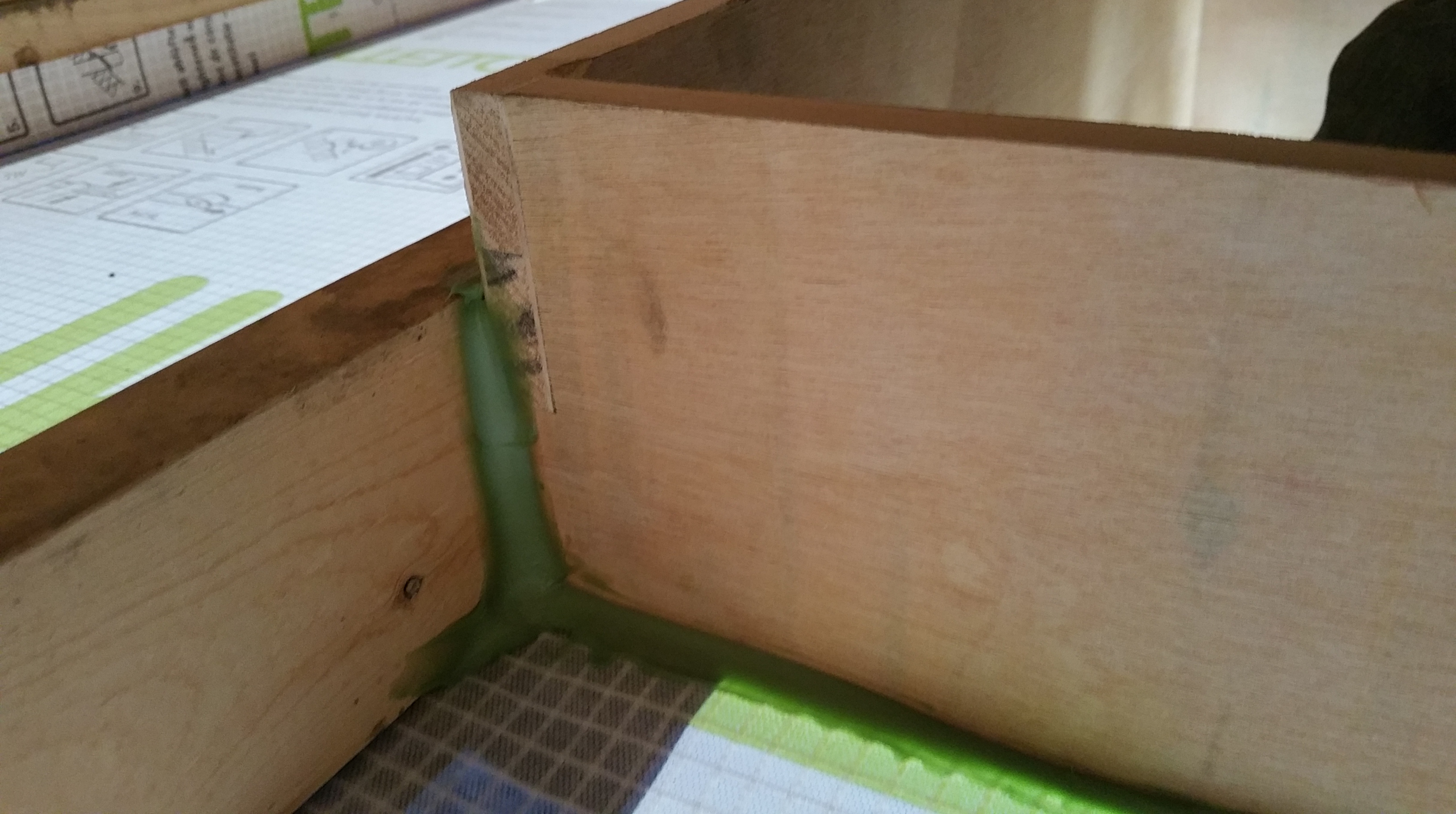
Air sealing the connections between the Intello, the Battic frame, and the roof trusses in the attic.
Using HF Sealant to make the connections as air tight as possible.
Once the outside perimeter of the Battic frame had been air sealed to the Intello, the only place left for air infiltration was where the lid would meet the frame of the Battic hatch once it was installed (more on this later when I discuss my first blower door test).
There was some additional framing required, but it was just a couple of “headers” between the roof trusses to add structural integrity to the two shorter sides of the Battic frame.
Battic frame with additional 2×6’s on one of the short sides.
Since we were using a significant amount of blown-in insulation in the attic, it made it necessary to build up the sides of the Battic frame in the attic with some plywood to get the top of the opening above where the insulation would eventually stop.
Here’s another view of the 3 sides of plywood installed:
The fourth and final side of plywood was installed just prior to blowing in the insulation — in the interim this made getting in and out of the attic much easier.
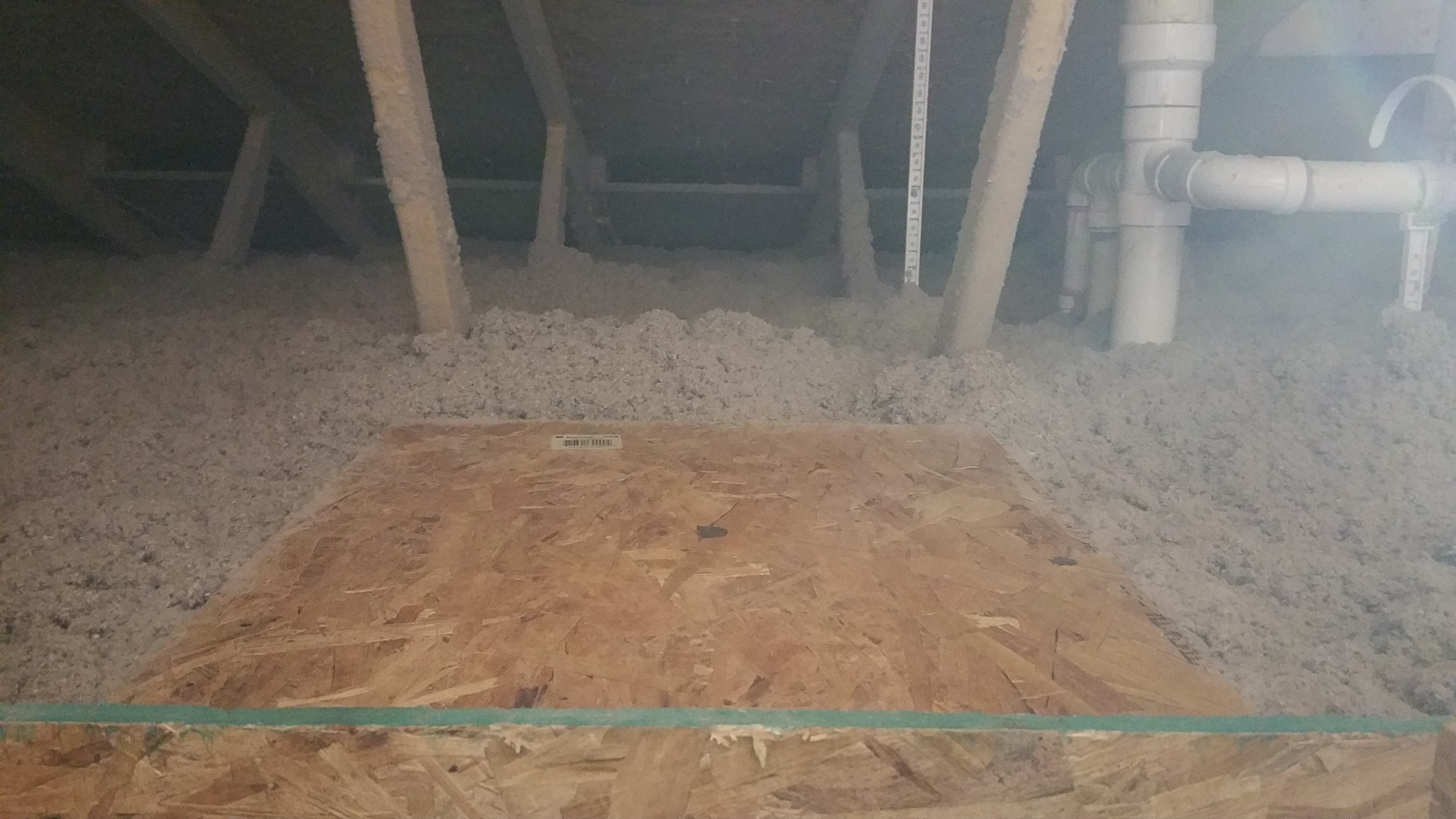
After a couple of practice attempts, it quickly became apparent that raising and removing the lid once in place, and fighting to get it back down into the master bedroom closet, wasn’t worth the trouble. Instead, I built a small bench in the attic next to the Battic frame so I could push the lid up above the level of blown-in insulation, this way it could have somewhere to safely sit while dealing with any issue in the attic.
Battic lid resting on the bench.
It’s very easy to grab the lid off the bench and bring it back down into position while slowly walking down the ladder in the master bedroom closet to make the final connection/seal.
Although the installation process was fairly straightforward and headache free for the Battic product, if I had it to do over, I think I would have the attic access point on the exterior of the structure, for example, on the gable end of the house in the backyard.
Putting the access point above the air barrier would make meticulously air sealing the entry point for the attic less important, so keeping water out of the attic would be the main goal. An additional plywood buck would’ve been necessary, replicating what I did for our windows and doors (more on this later), but I think it still would’ve been the better option overall.
Putting the attic access on the exterior of the house would also mean avoiding an ugly hole somewhere in our drywalled ceiling. No matter how nicely trimmed out, these attic access points on the interior of a home never look right to me. We’ve tried to hide ours as much as possible by sticking it in our master bedroom closet, which has worked out well, but not having one at all on the interior of the house would make for a cleaner, better solution in my opinion.
If granted a do-over, I would also add a cat walk in the attic through the roof trusses. This would make getting to any point in the attic much easier to navigate. It would also help to avoid disturbing the blown-in insulation too much.
And here’s a photo of the bench in the attic, next to the opening for the Battic attic hatch, after the blown-in insulation was installed:
Sealing the Seams and Penetrations in Zip Sheathing
Note:This post will concentrate on the Zip sheathing itself, as it relates to seams and penetrations. I’ll address how I sealed around openings for windows and doors, along with our attic access hatch through the Intello on the ceiling in separate, future blog posts.
We used Zip sheathing as our WRB (weather resistant barrier — sometimes it’s referred to as a water-resistant barrier) based largely on Hammer and Hand projects:
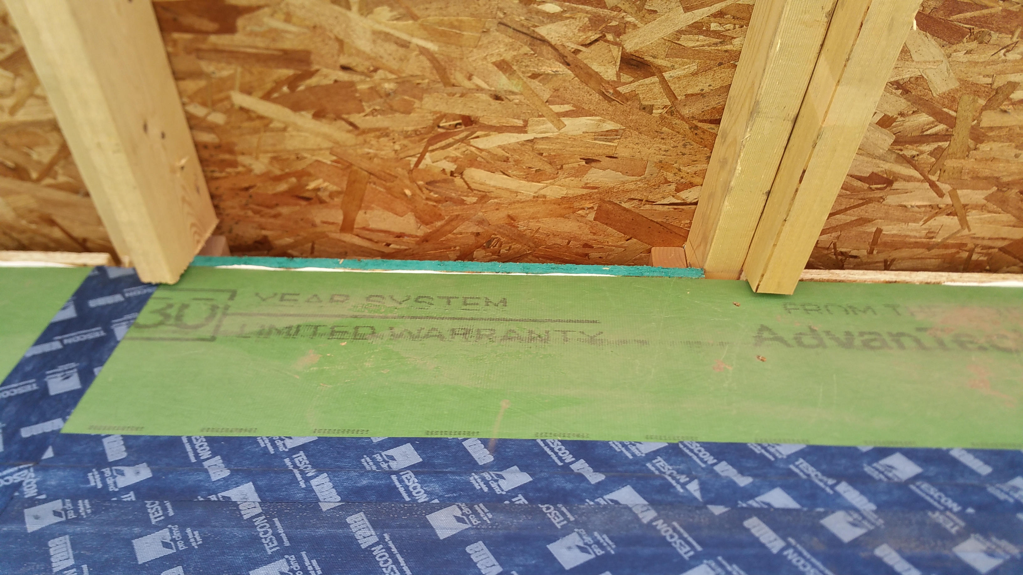
As the 7/16″ Zip sheathing went up, I taped most of the seams with Pro Clima’s 3″ Tescon Vana tape (available at 475 HPBS), but also their Contega tape(6″ wide), which I used mainly for outside corners and larger seams in the Zip (mainly where the horizontal seam in the Zip transitioned from the exterior walls of 2×6 framing to the roof trusses — shown in a photo later in this post).
My wife and daughter also cut up the Tescon Vana tape into small pieces in order to cover all the nail and screw holes in the Zip sheathing.
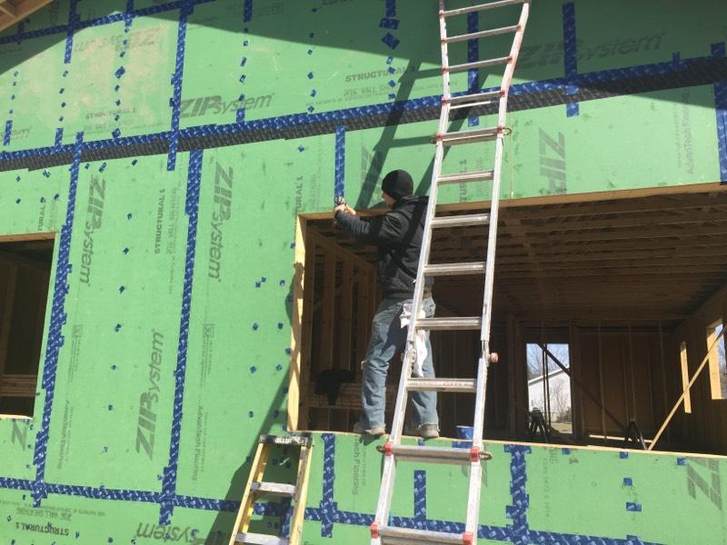
The Beast and Eduardo team up to tape the nail and screw holes on the lower sections of Zip sheathing around the house.
The nail holes were initially sealed with HF Sealant, also available from 475 HPBS, thus giving them double coverage — this was discussed earlier, here:
And here’s a good video discussing the Zip sheathing and its benefits (and its place in the evolution of building science):
If I had it to do over, I think I might be tempted to use 1/2″ exterior grade plywood as my sheathing (there are any number of WRB options these days). This would be sealed on the exterior side with either a liquid membrane, like Prosoco’s Cat 5, or a peel-n-stick tape like Henry’s Blue Skin, or even another 475 HPBS product Solitex Mento 1000.
The Zip sheathing works, and the exterior green skin held up nicely during construction, even as it sat exposed for nearly 10 months after we fired our GC’s and struggled to keep the project moving forward. Nevertheless, it is little more than glorified OSB, which comes with certain inherent weaknesses.
Matt Risinger does an excellent job of delineating the cost/benefits of using either OSB or CDX plywood as a sheathing material:
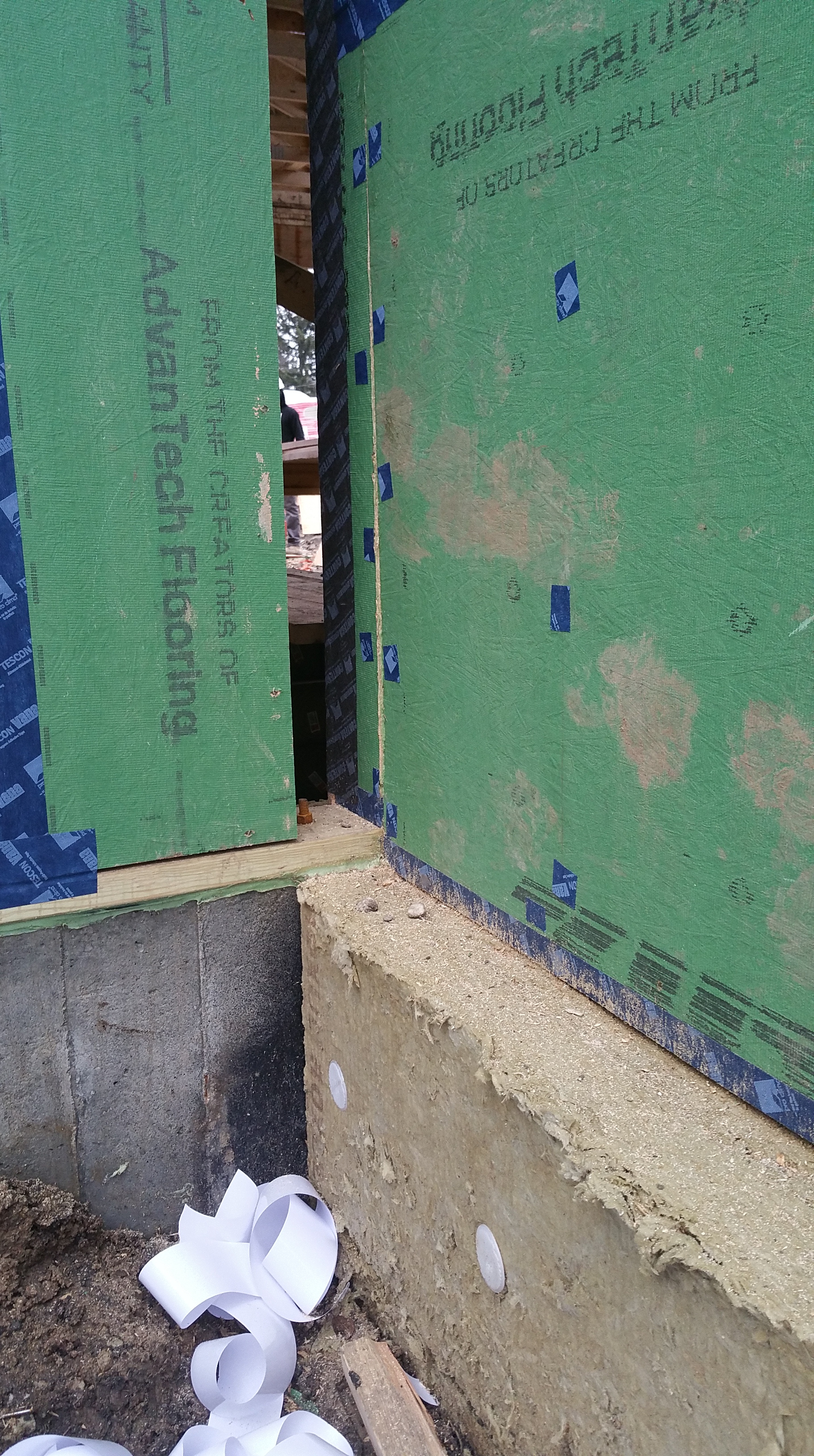
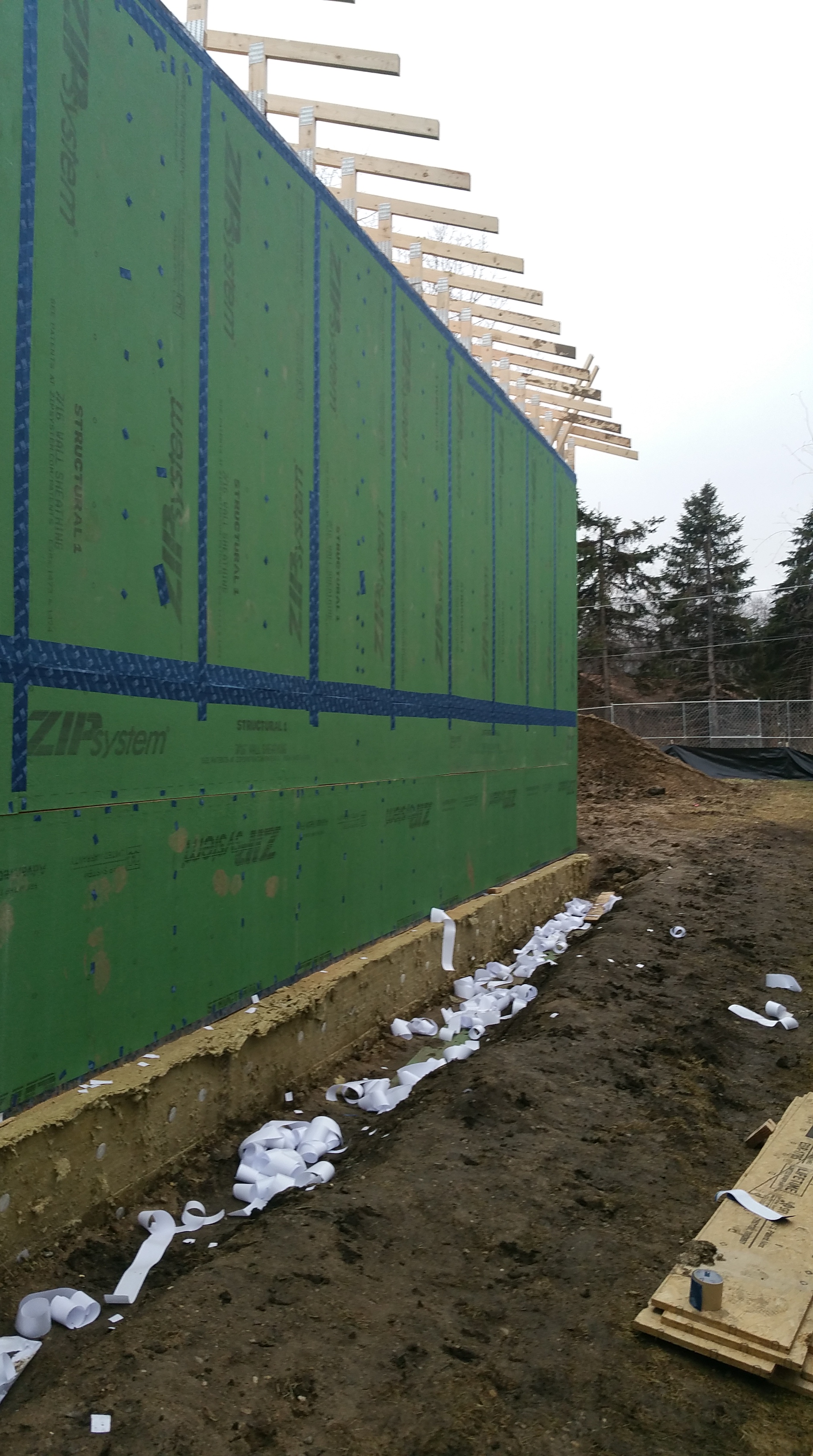
Garage (at left) house (at right) connection. Gap will eventually be filled with 4″ of Roxul Comfortboard 80.
Closer view of this same garage – house connection. Flashing will cover the bottom of the Zip and then carry over the top of the Roxul that covers the foundation.
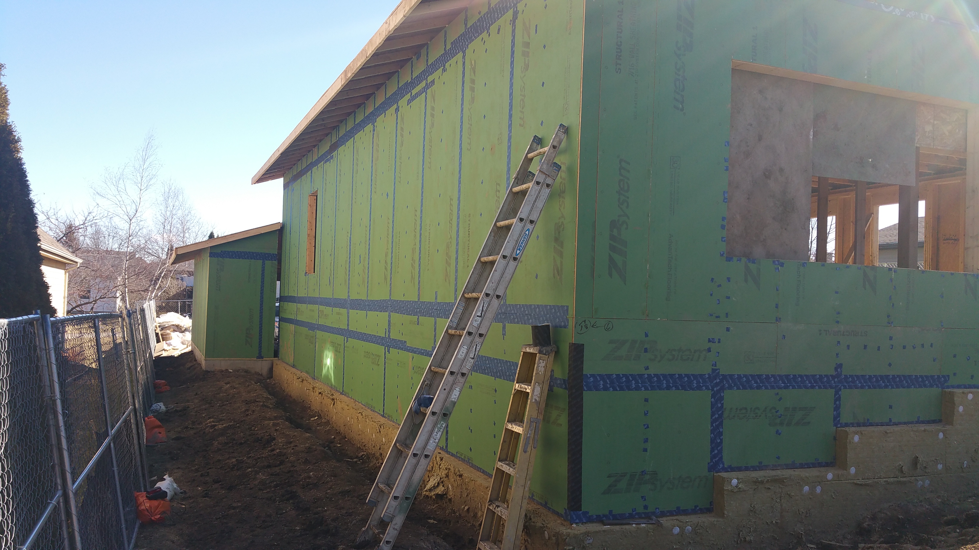
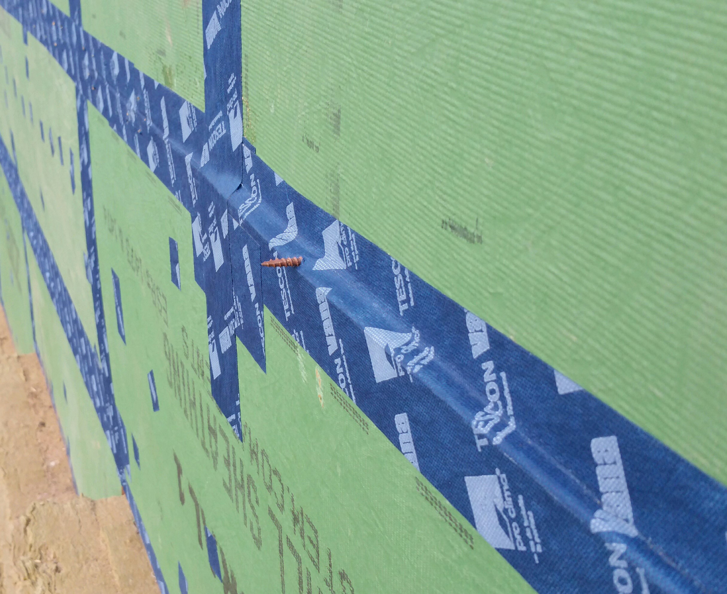
View of the north side of the house as Tescon Vana tape air seals the nail holes and the seams in the Zip sheathing.
View of the West facade with Tescon Vana tape, along with the black Contega tape at larger seams (e.g. where the walls meet the roof trusses) and outside corners.
West facade as taping proceeds.
Northwest corner of the house, transitioning from the Tescon Vana to the black Contega tape at the corner.
Finishing up some of the final seams in the Zip on the West facade.
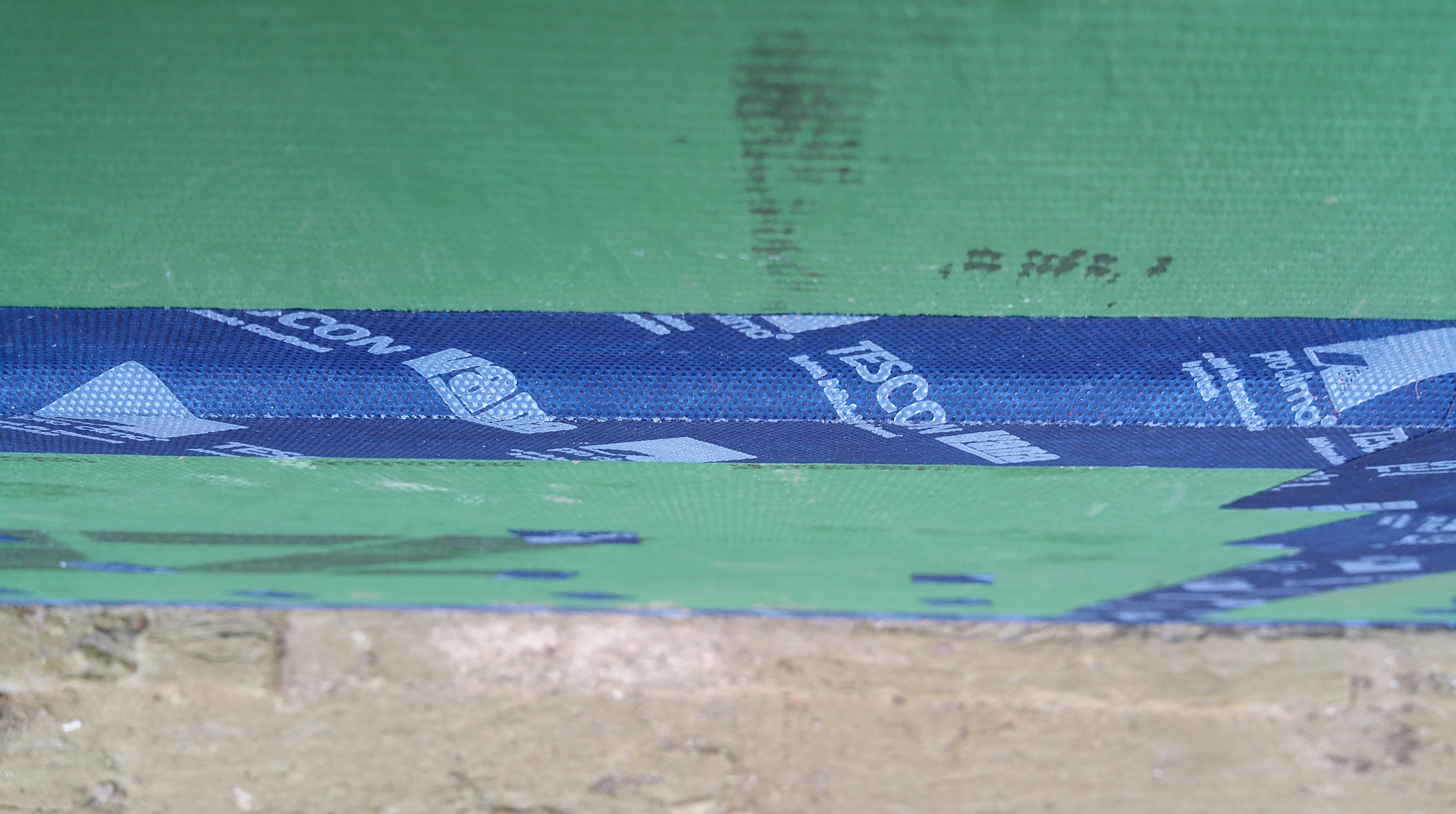
Once the Zip was fully installed, it was readily apparent that some of the seams, especially near the base of the first floor where a horizontal seam ran around the entire structure, would need to be tightened up.
Here’s a view looking down on one of these areas where the Zip sheathing did not sit flat against the framing members:
Horizontal seam in Zip sheathing refusing to lie flat against the 2×6 framing members.
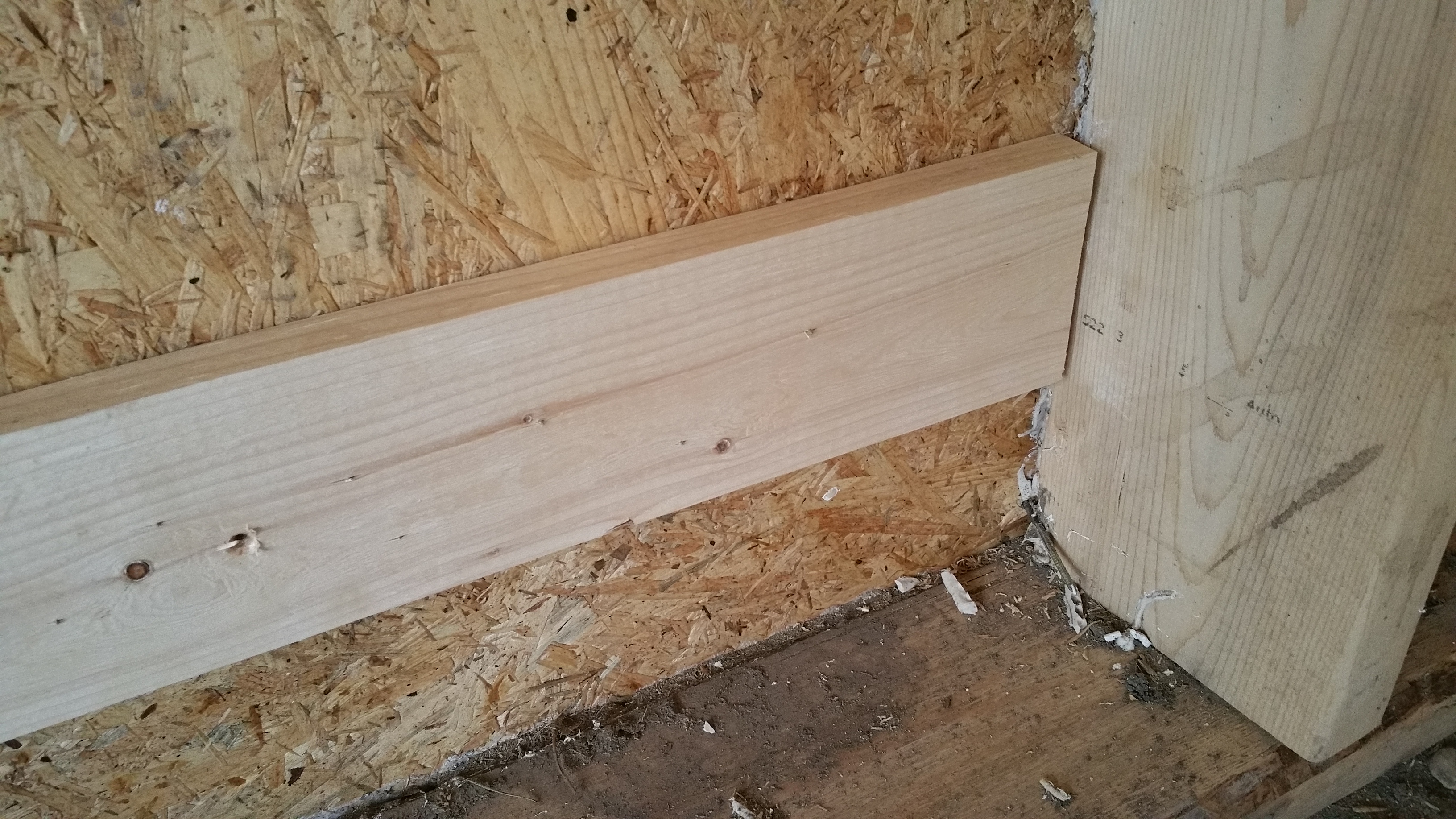
Using a 1×4 in each stud bay, I was able to pull the seam in the Zip sheathing together. It wasn’t always perfect, but the difference was visibly significant and in most areas well worth the effort.
Placing a 1×4 into position over the seam in the Zip, I would drive a couple of screws towards the exterior.
1×4 used to pull an unruly seam in the Zip sheathing together.
Screw from the interior poking outside as it initially gets the 1×4 in place.
Once securely attached from the interior, I went outside and drove several screws into the Zip, both above and below the seam in the Zip, to pull the seam tight to the 1×4. At that point, I could go back inside and remove the two screws that were driven towards the exterior.
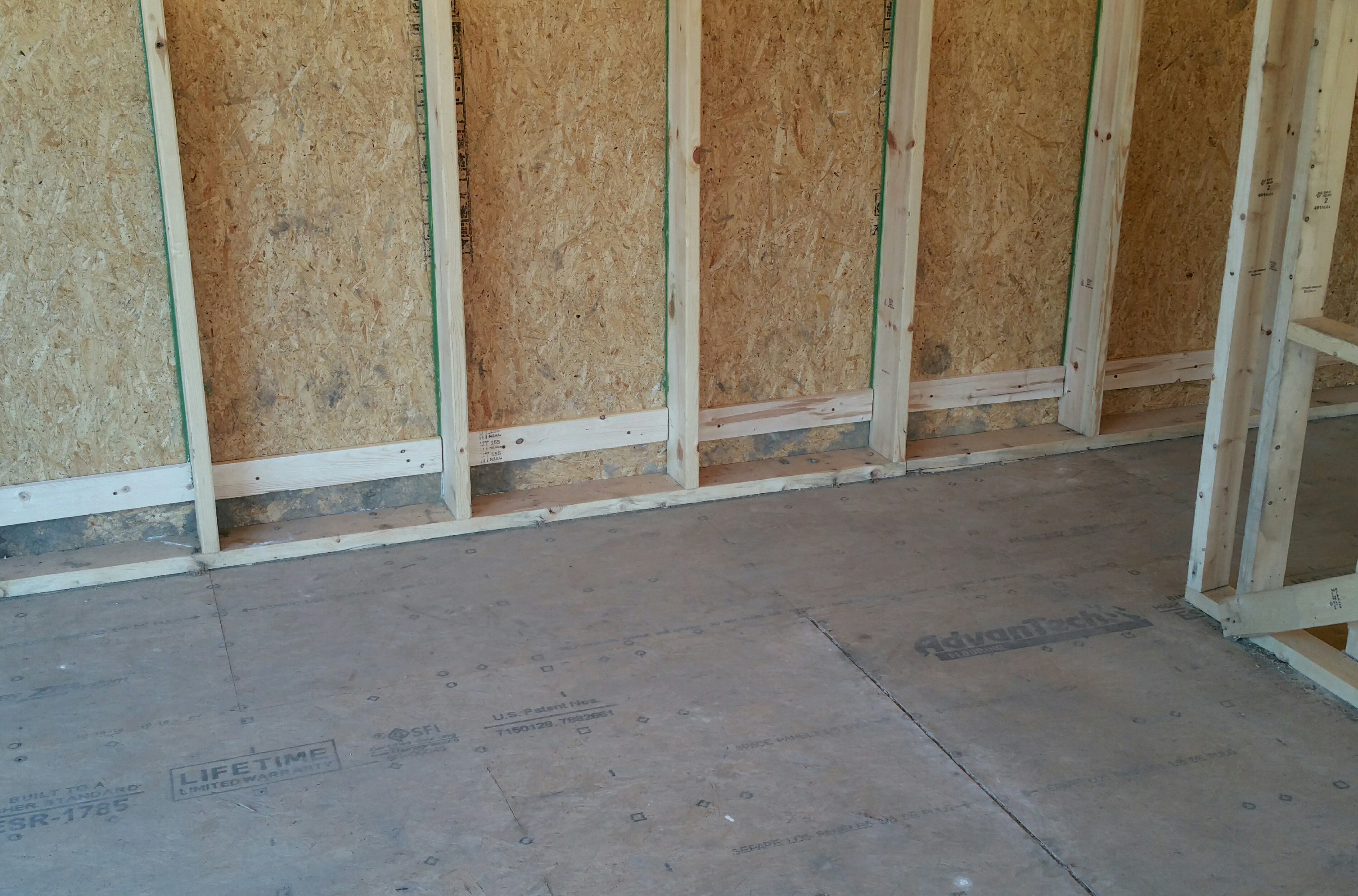
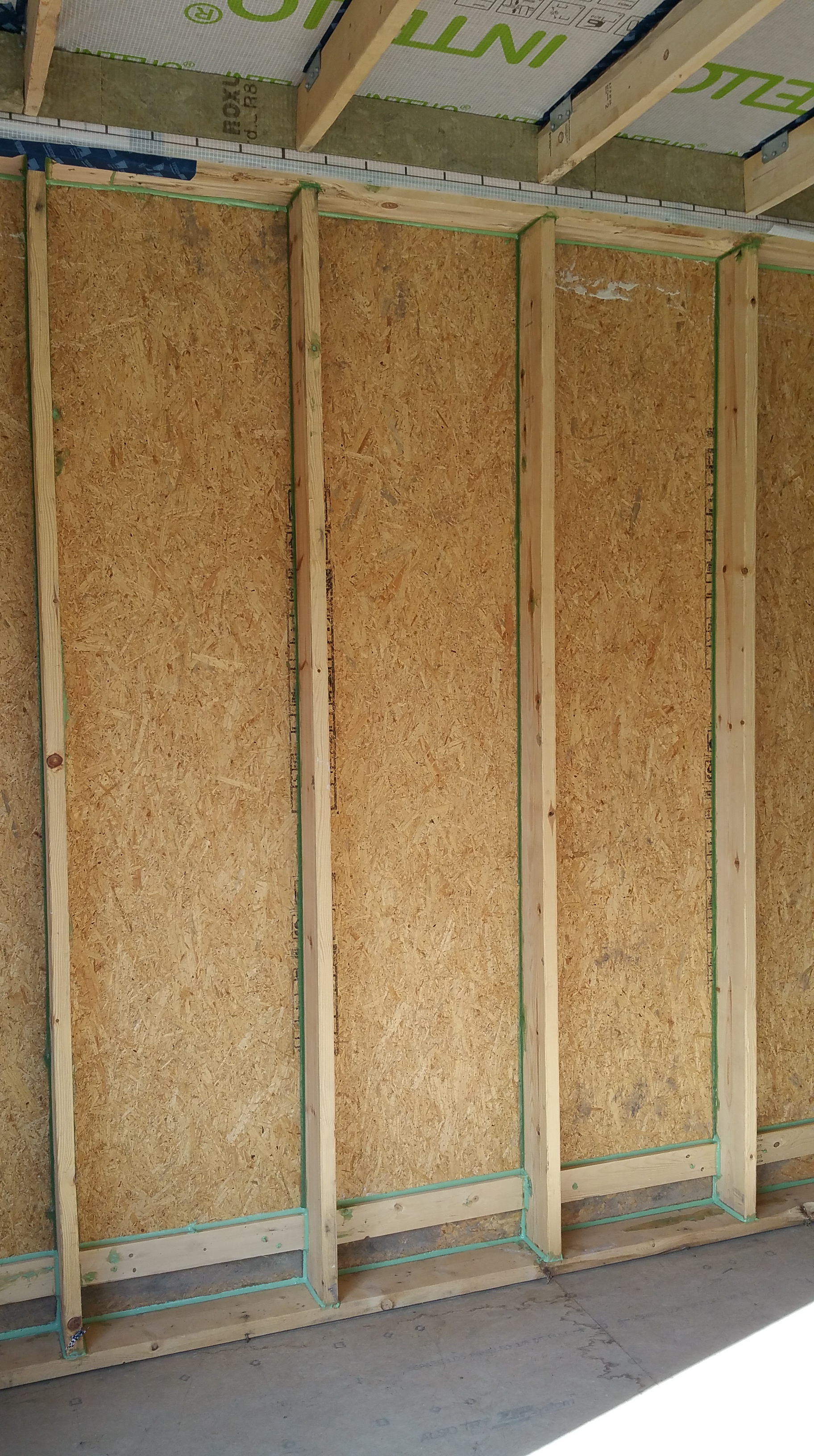
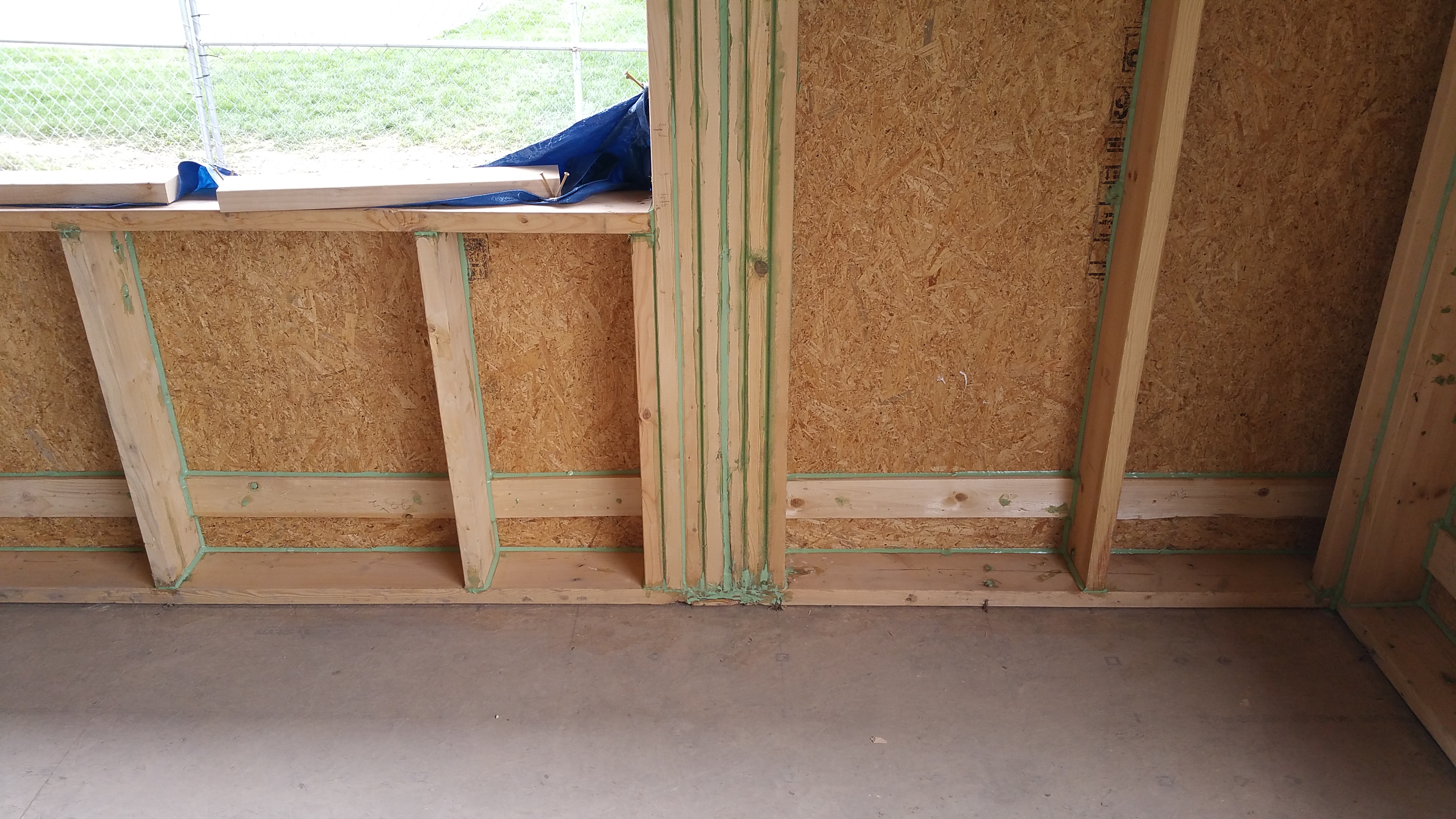
In addition to air sealing the exterior side of the Zip sheathing, I also invested some time in air sealing the interior side of the Zip as well. Below is a long view of several stud bays with 1×4’s installed, but before air sealing gaps around the 1×4’s and lower areas of the stud bays with HF Sealant.
Long view after applying the HF Sealant:
Close-up of the interior side of the Zip sheathing meeting a 2×6 framing member in a stud bay after applying a thick bead of HF Sealant:
Close-up of lower area of a stud bay after air sealing with the HF Sealant (it transitions from a light to darker green as it dries):
1×4 installed and HF sealant applied to all gaps and screw/nail holes in the stud bay.
I held off on using the HF Sealant at the wall sill plate/subfloor connection until just prior to installing the Intello on the walls since this area constantly attracts dirt and debris.
Sealing on the interior side with HF Sealant, even between vertical framing members, means that even if there are any weaknesses in either the Zip sheathing or the Tescon Vana tape at these points, air won’t find an easy way in, since it will be blocked from the interior side as well (there won’t be a difference in air pressure to help the outdoor air make its way indoors).
This kind of redundancy in air sealing should give the house long-term protection against air leaks, thereby aiding the long-term durability of the structure, as well as making it a much more comfortable environment to live in.
Using HF Sealant between vertical framing members.
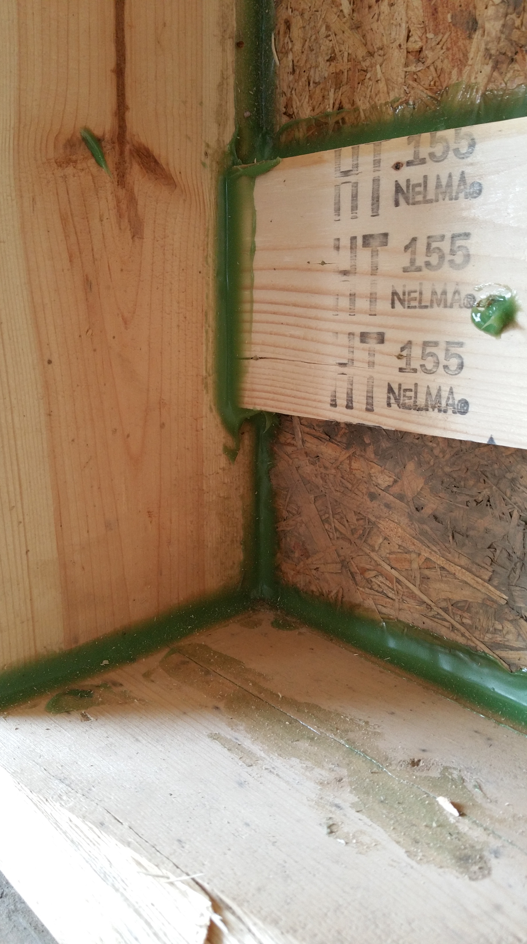
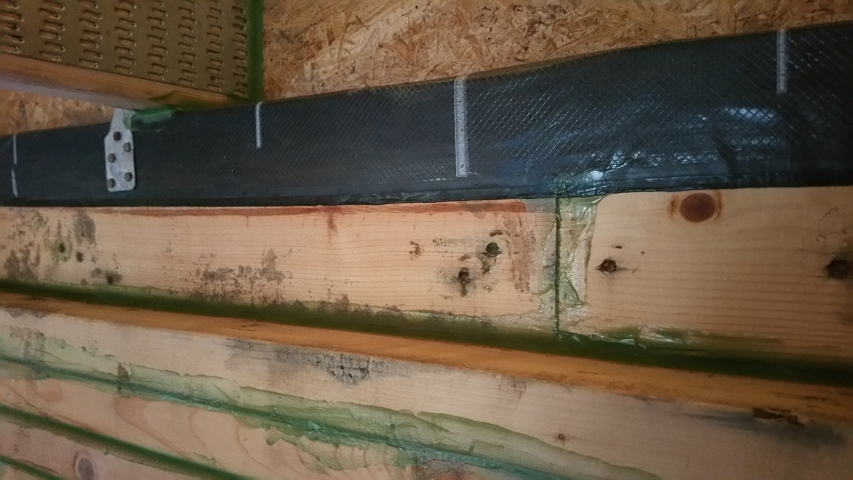
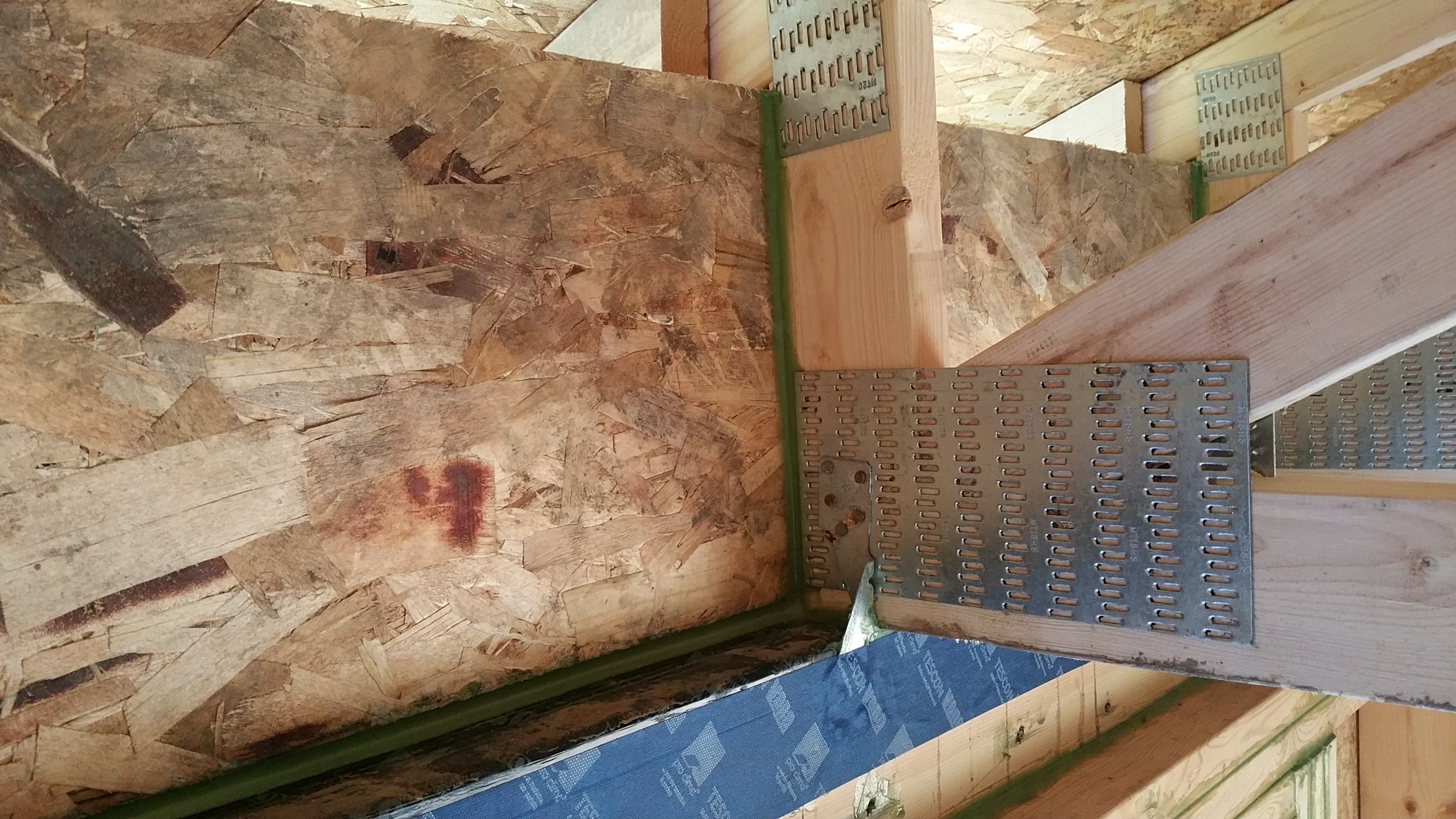
I also spent some time on the roof trusses, sealing around nails, the top plates of the exterior walls, and the many Zip-framing member connections in what will eventually be the attic.
Sealing around fasteners and framing in the attic with HF Sealant.
This had less to do with air sealing and more to do with preventing any potential water intrusion since this area is technically above our ceiling air barrier (the Intello), which is detailed here:
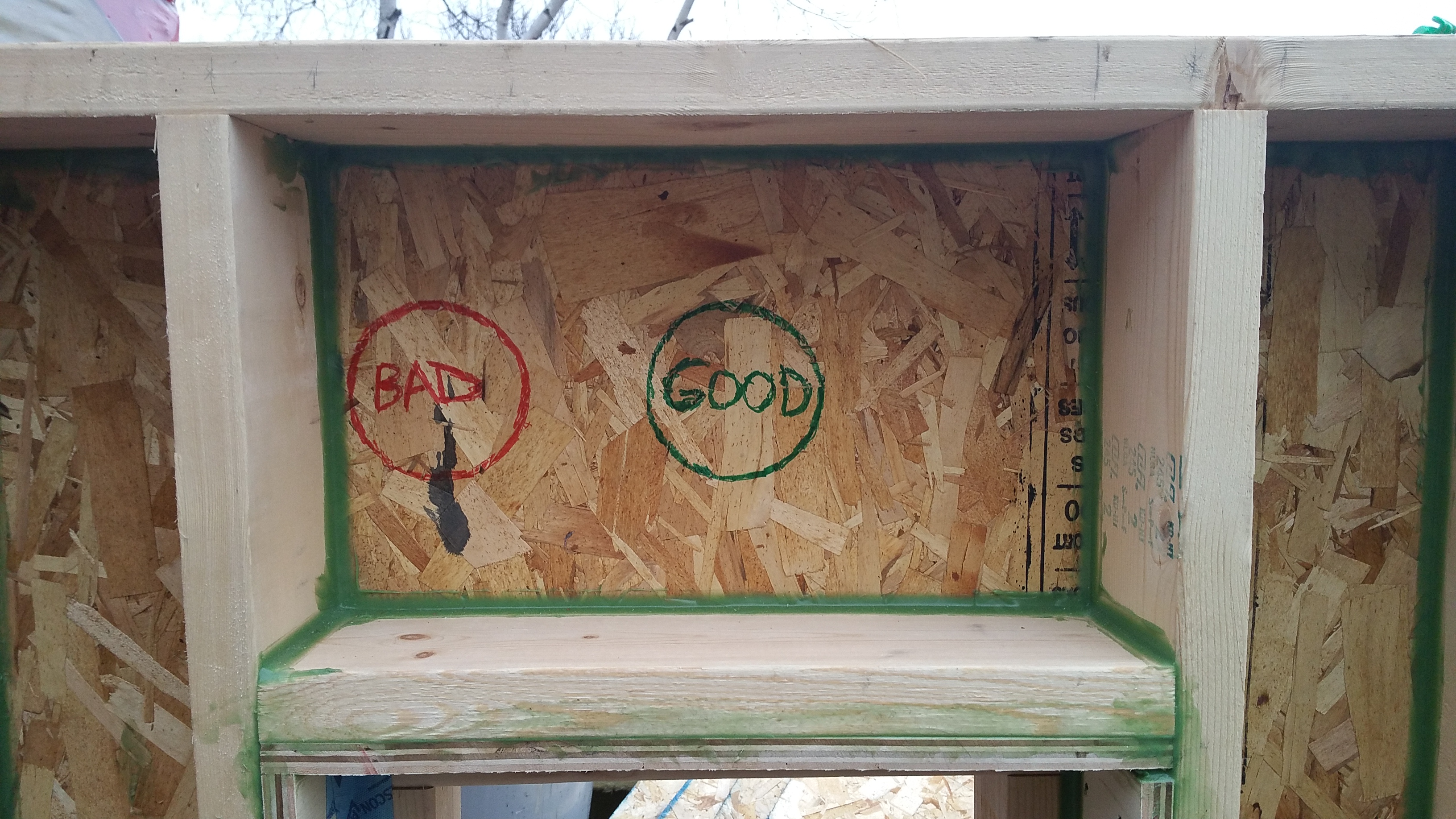
This proved helpful when explaining to the various subs how to help me protect the air barrier — especially when it came time to drill holes through the Zip sheathing. Of particular importance was making holes closer to the center of a stud bay, as opposed to hugging a corner or side of one of the 2×6 framing members. A hole cut too close to a stud or a roof truss is much harder to properly air seal.
Interior side of our mock wall assembly showing how all penetrations through the Zip should be in the middle of our framing members. Our original plumber was the only trade that managed to screw this up (it’s no coincidence that he was also the only sub that we had to fire).
In effect, any time a sub had to make a penetration through the air barrier we discussed the details, and once the cut was made I immediately air sealed the penetration both on the exterior and interior side.
By sealing each hole in the Zip on both sides, again I hope it ensures the long-term durability of the overall structure. The main argument for this strategy assumes the exterior side of the sheathing will face more extreme temperatures, and fluctuations in humidity, and presumably even wind-drive rain if/when it gets past the siding and 4″ of Roxul insulation, putting it at greater risk of failure (especially in the long term). By taking the time to air seal the interior side, it just gives the overall air barrier, and therefore the structure, a better chance at avoiding air and water intrusion (that’s the goal anyway).
For air sealing I used a mix of tapes, HF sealant (later even some Prosoco products), EPDM Roflex gaskets, and duct seal.
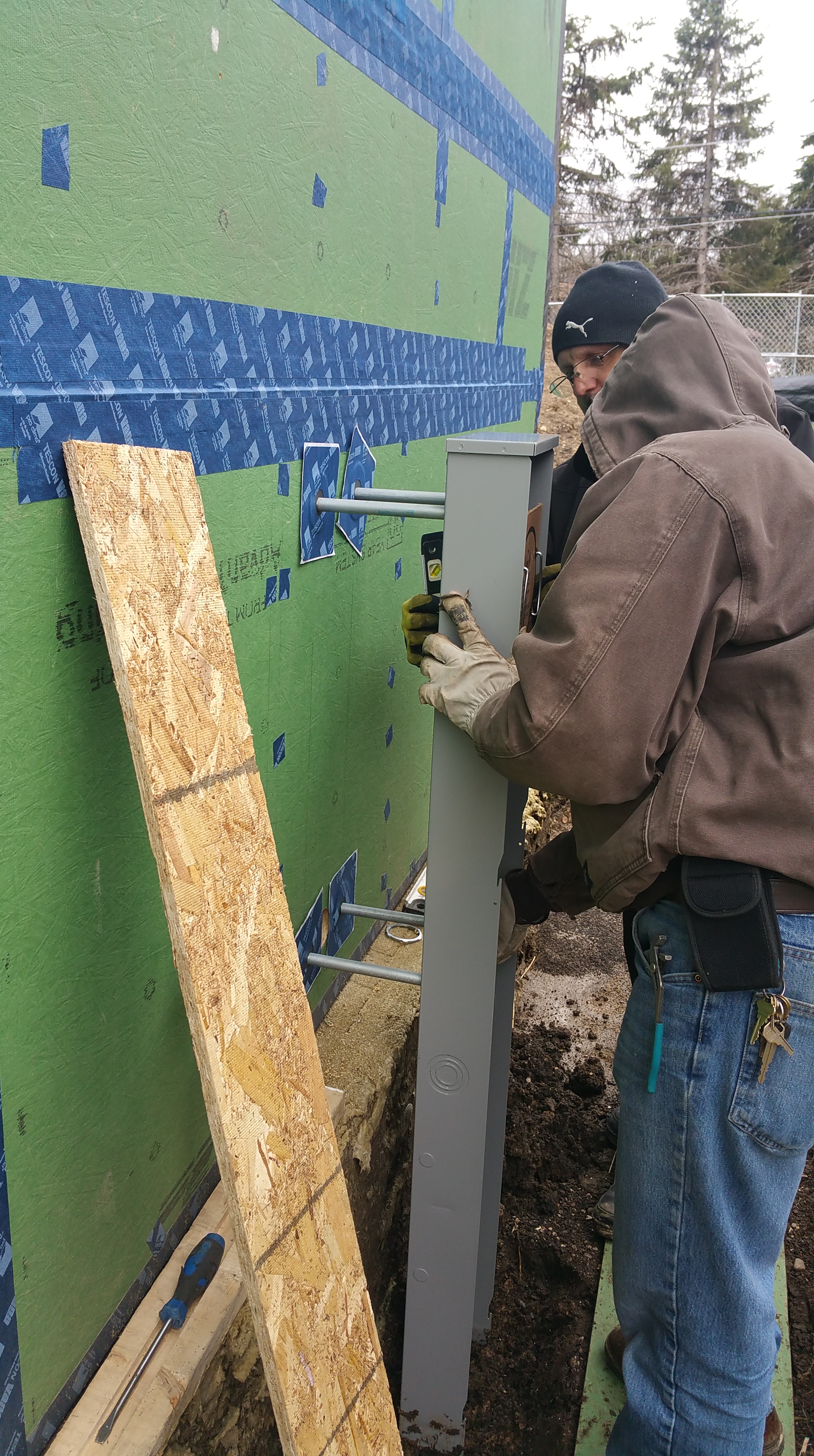
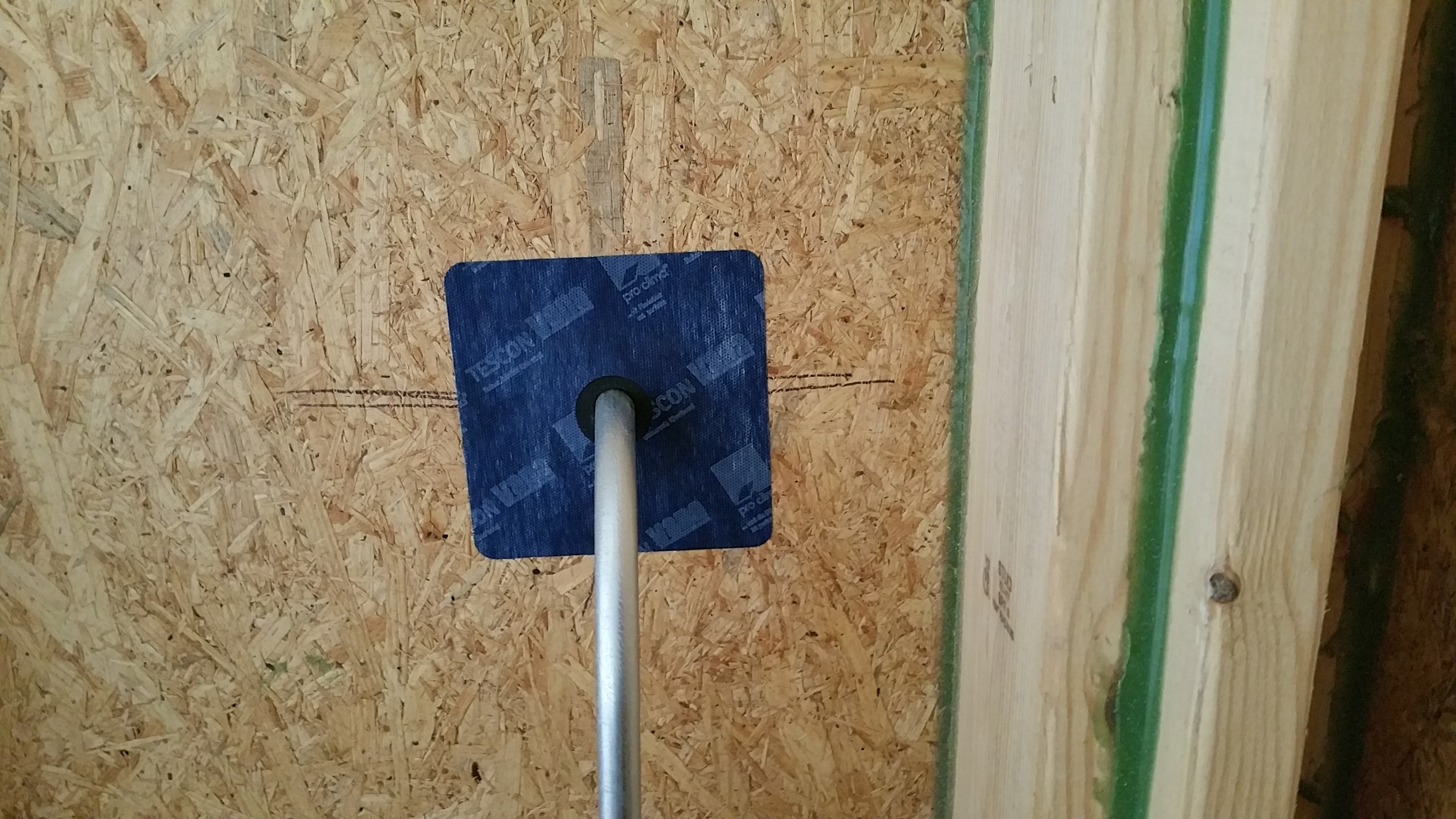
The penetrations for electric service were my first go at using the Roflex gaskets:
John and Danny installing the electric meter.
The smaller diameter Roflex gasket comes with its own Tescon Vana tape, which makes installation straightforward.
Electric meter with Tescon Vana – Roflex gaskets installed.
Exterior view of electric Meter air sealed with gaskets and Tescon Vana tape:
Once sealed on the exterior side, I went inside to seal the penetrations for a second time:
Air sealing the electric meter on the interior side.
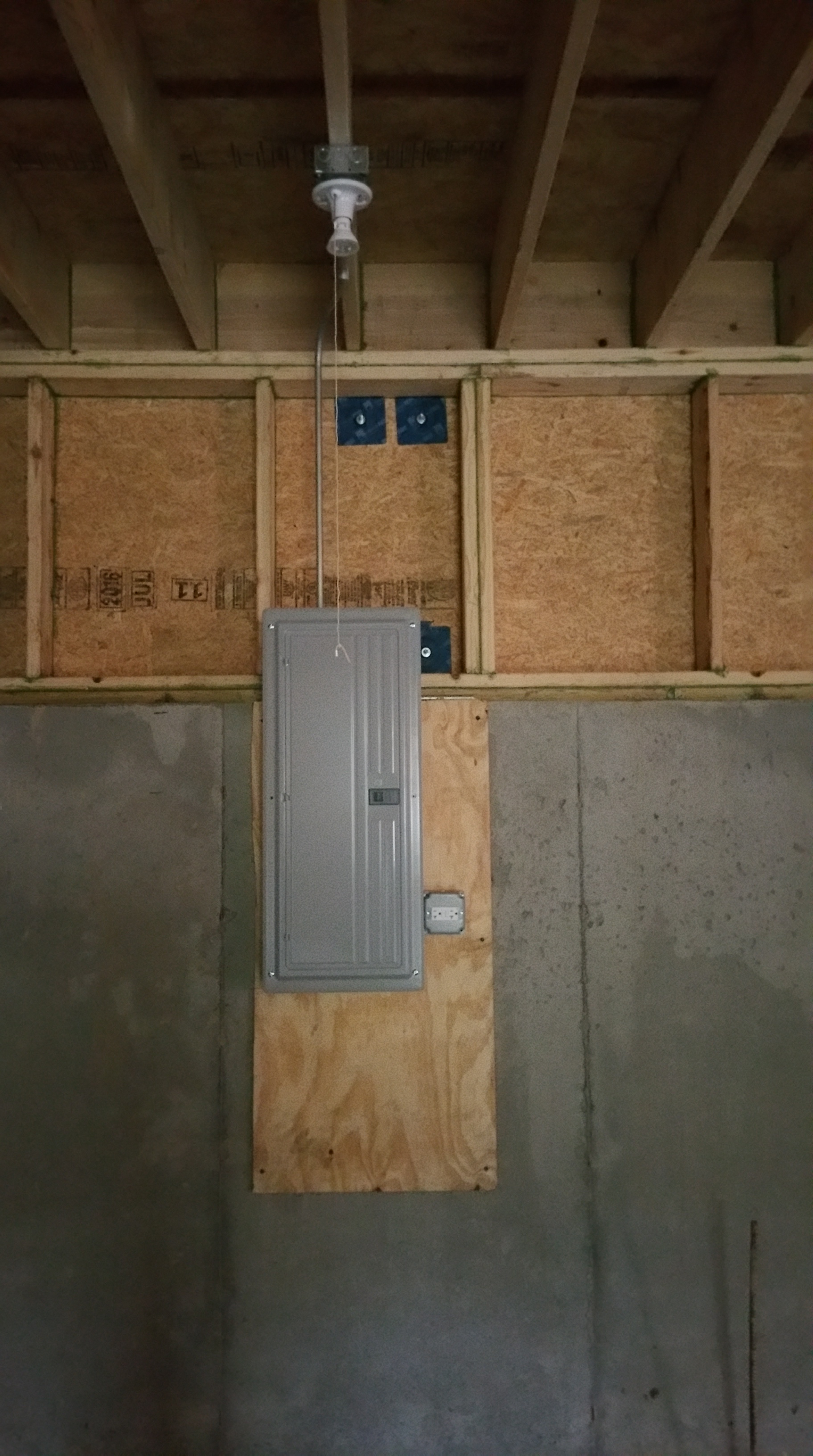
It was a big moment when the electric panel went in:
The house is ready for power.
The installation of our solar panels required air sealing two penetrations — one through the Intello on the ceiling on the inside of the structure, along with one exterior penetration through the Zip:
Details regarding the installation of our Solar array can be found here:
Solar disconnect (on/off) with its Tescon Vana gasket.
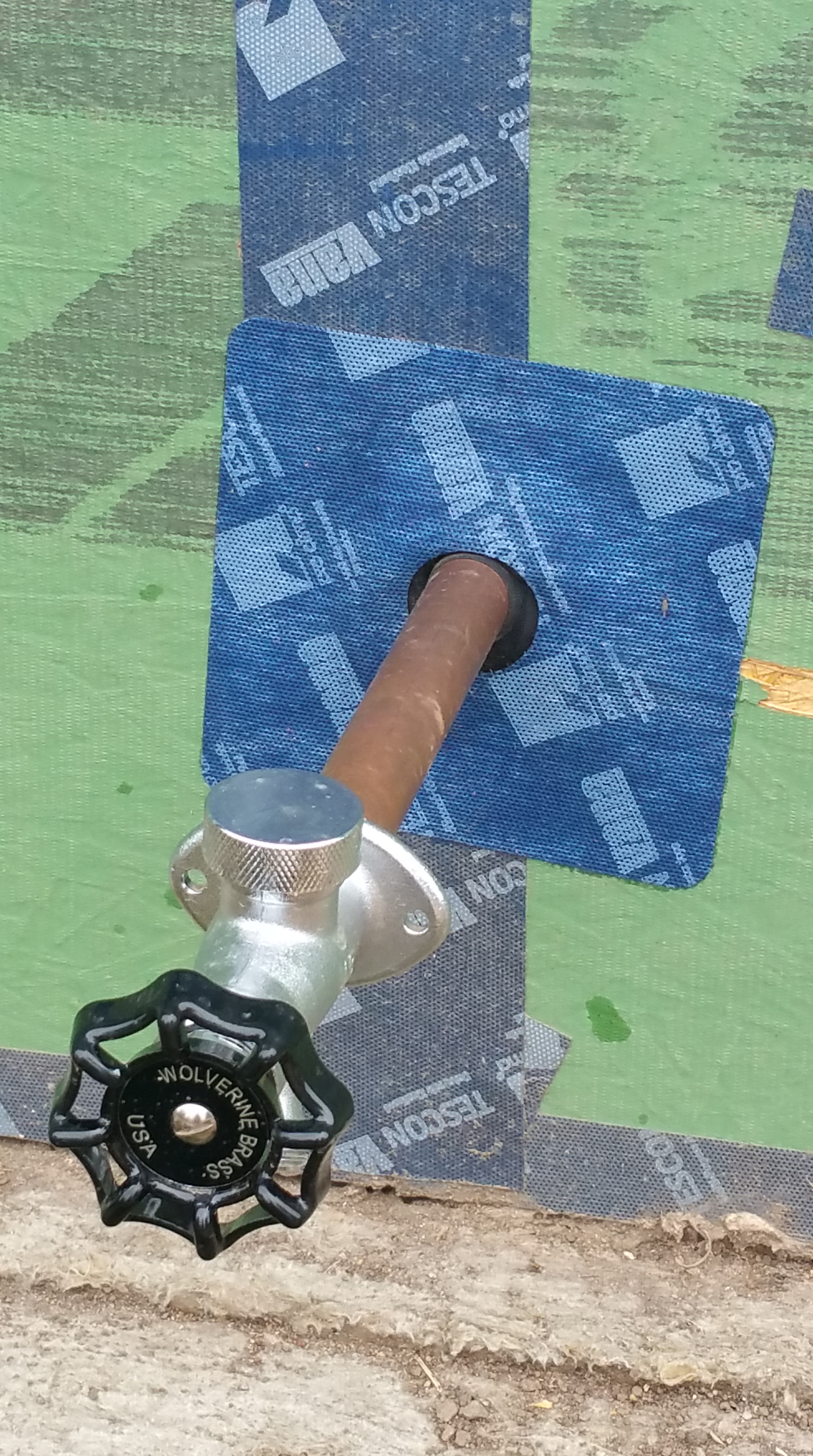
We also had two frost-free hose bibs, or sill cocks, installed, which also required gaskets on the exterior and interior sides of the Zip sheathing.
Frost free hose bib with gasket.
One of the big advantages a Roflex gasket has over using a sealant like the green HF Sealant, or Prosoco’s Joint and Seam, is the pipe can be moved in and out even after air sealing, which is especially helpful for installing siding later.
We left the sill cocks loose (unconnected to water supply line inside the house), allowing the siding guys to adjust in and out for a more precise fit of the charred cedar siding.
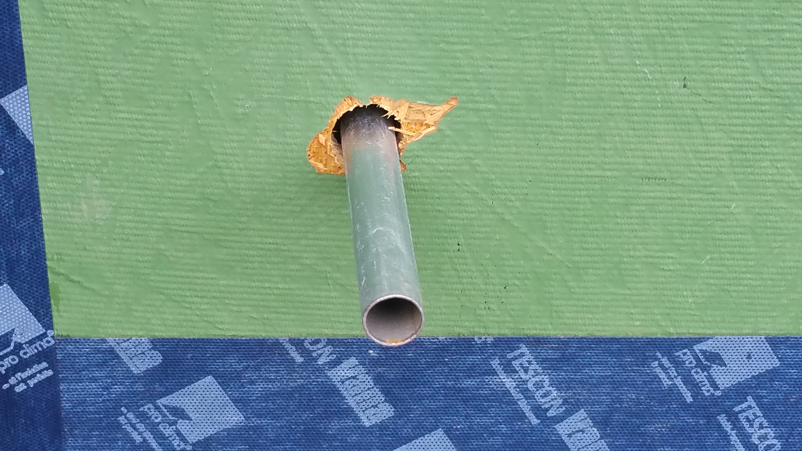
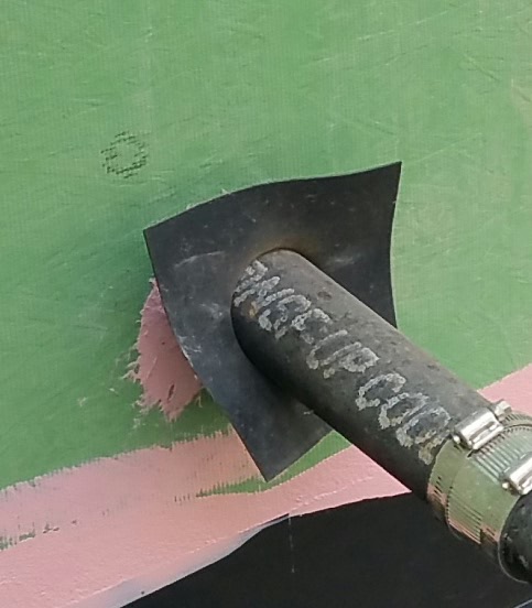
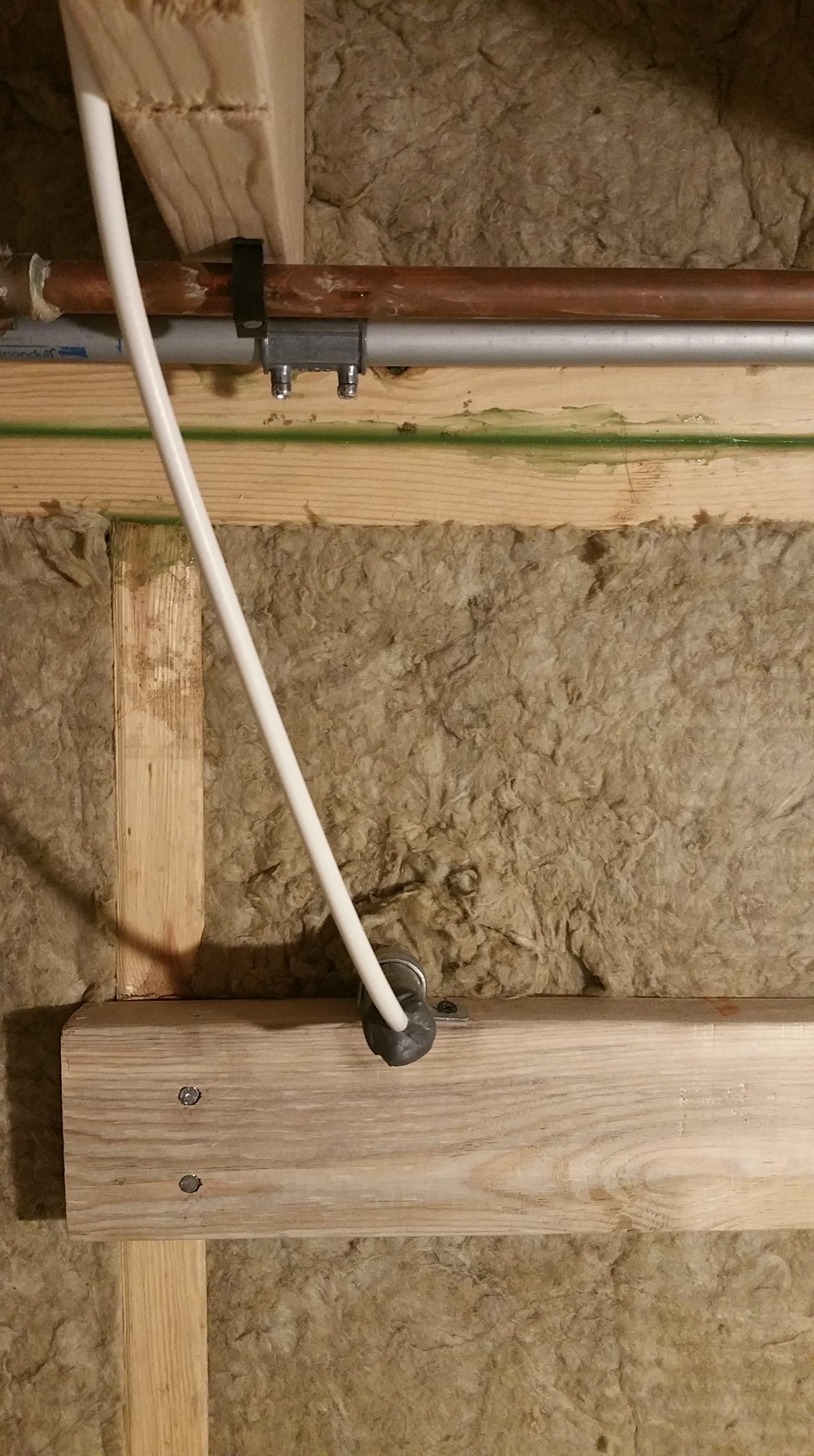
Below is an example of what conduit through the Zip sheathing looks like before it gets a gasket and some tape:
Penetration for conduit before gasket.
And here’s the conduit after the gasket and some tape:
Conduit after gasket.
Note the extended length of the conduit, anticipating our 4″ of Roxul covering the Zip, 2-layers of furring strips (vertical then horizontal — for vertically oriented siding), and the eventual charred cedar siding.
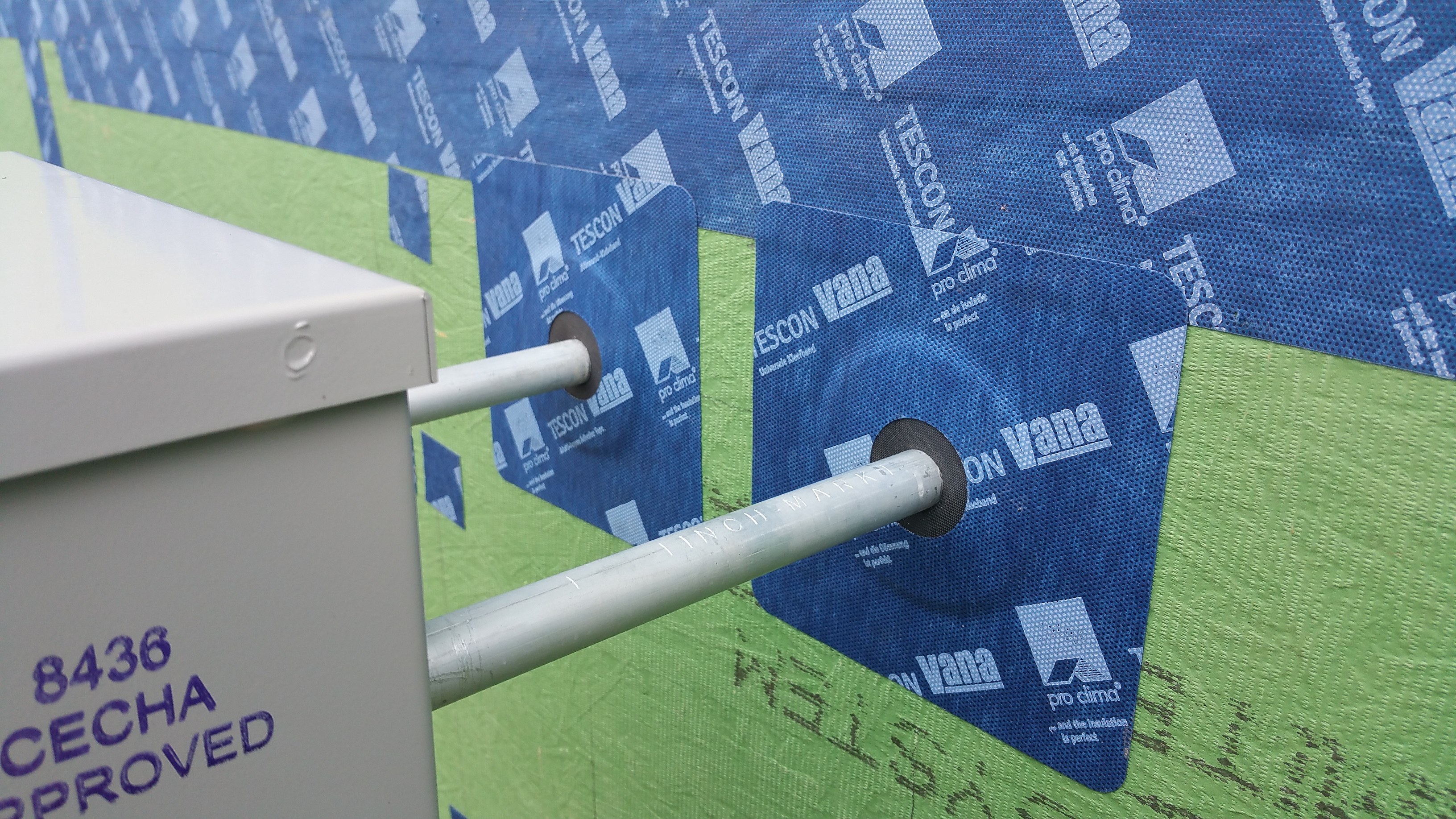
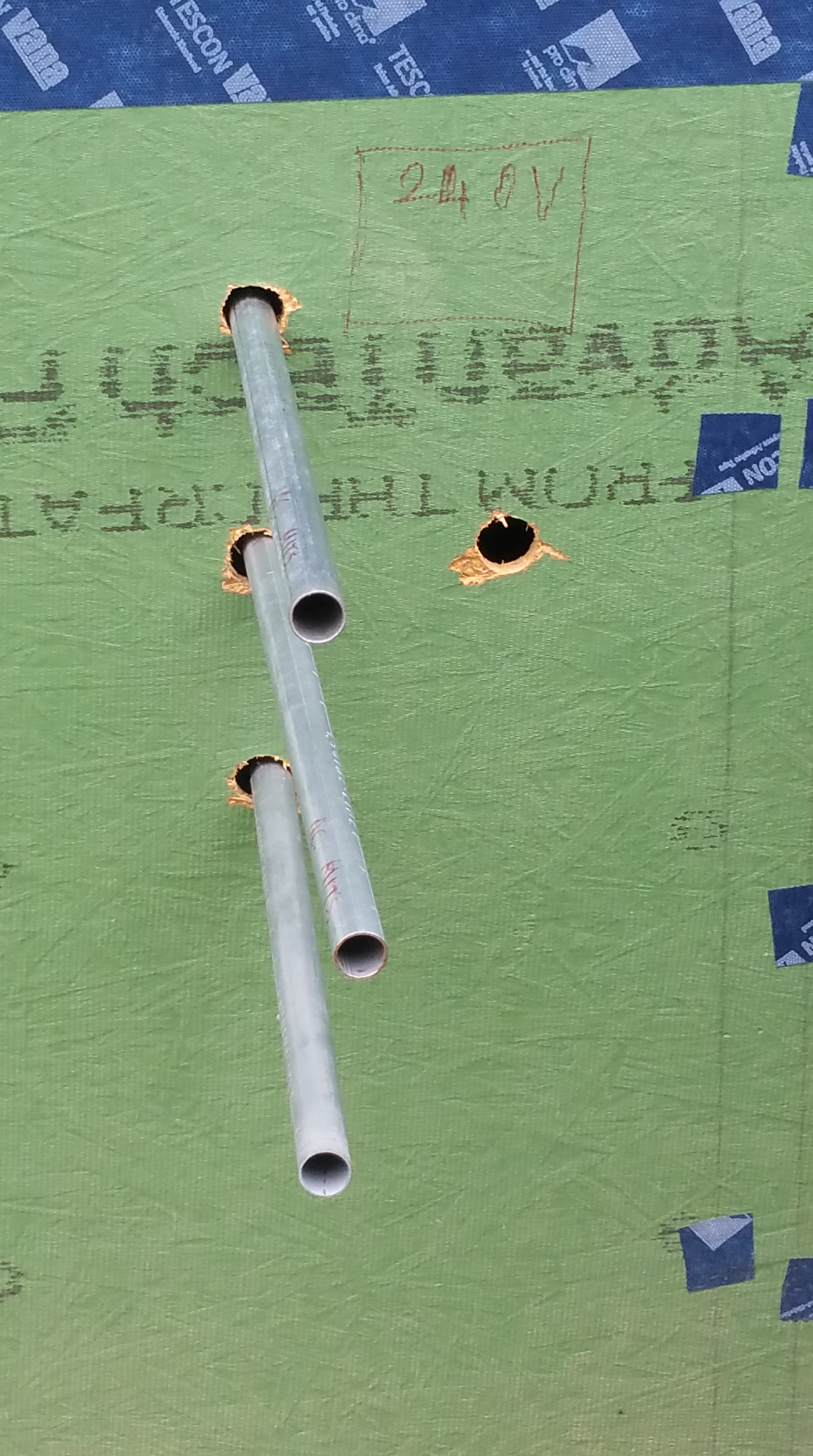
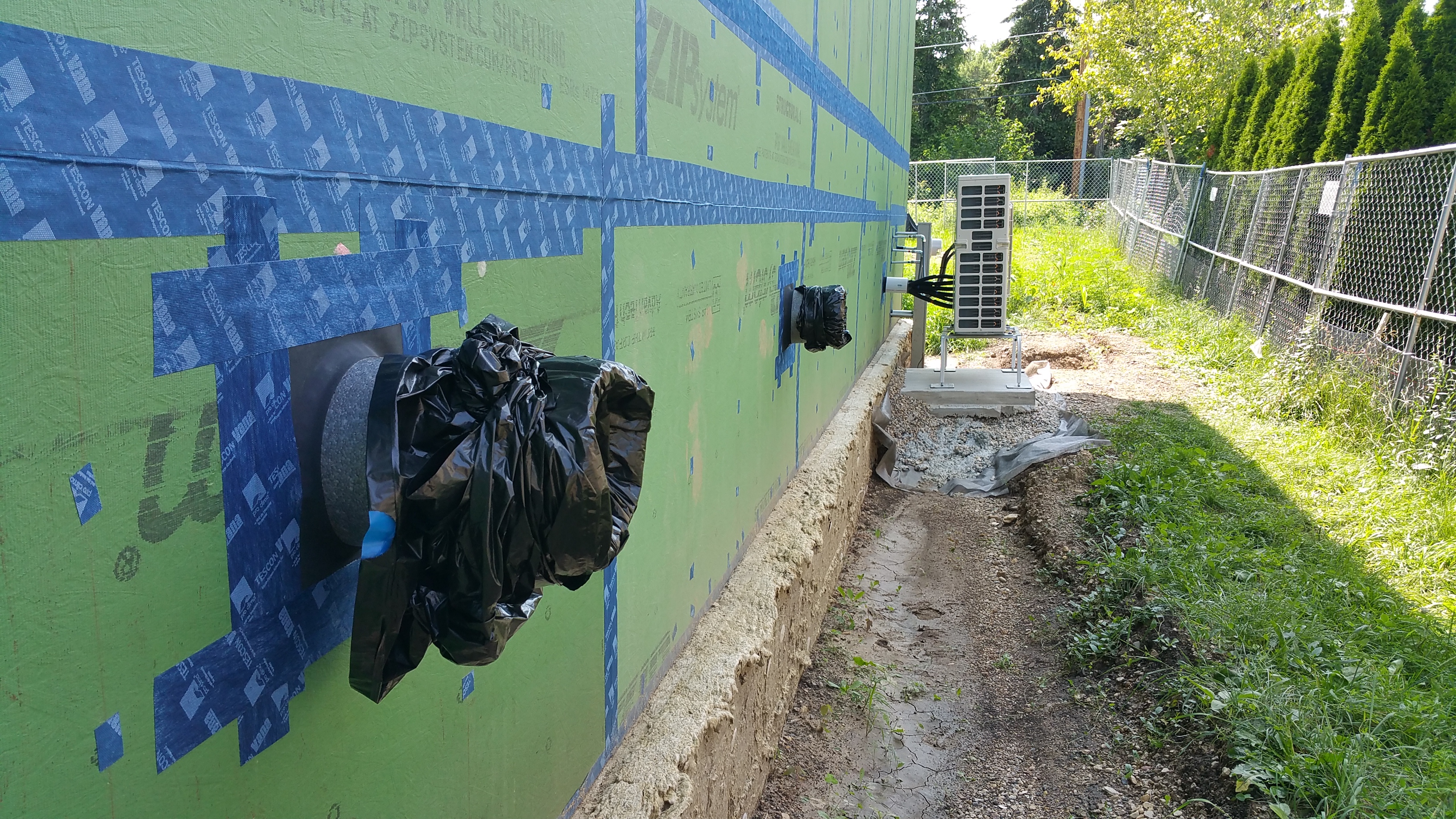
The photo below shows the penetrations, along with multiple lines of conduit, for our eventual ductless mini-split Mitsubishi heat pump system. The empty hole will be our disconnect for the heat pump. I’ll go into the details of our ductless mini-split system in a future post.
Penetrations for our Mitsubishi heat pump system.
Same series of conduit pipes after gaskets and being connected to the compressor outside:
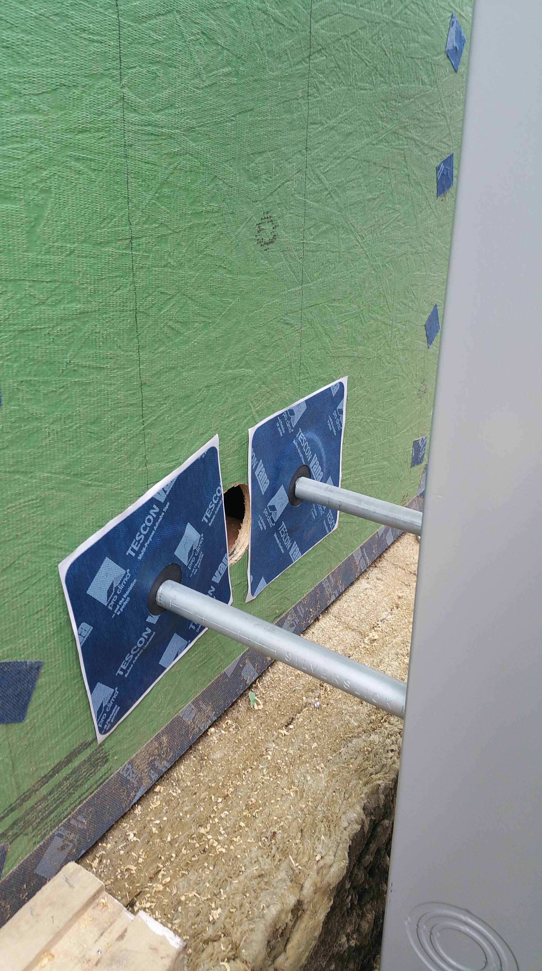
In addition to the conduit for electrical hook-up, the Mitsubishi heat pump system required a separate penetration for running the refrigerant lines to the compressor:
Hole cut for the heat pump refrigerant lines.
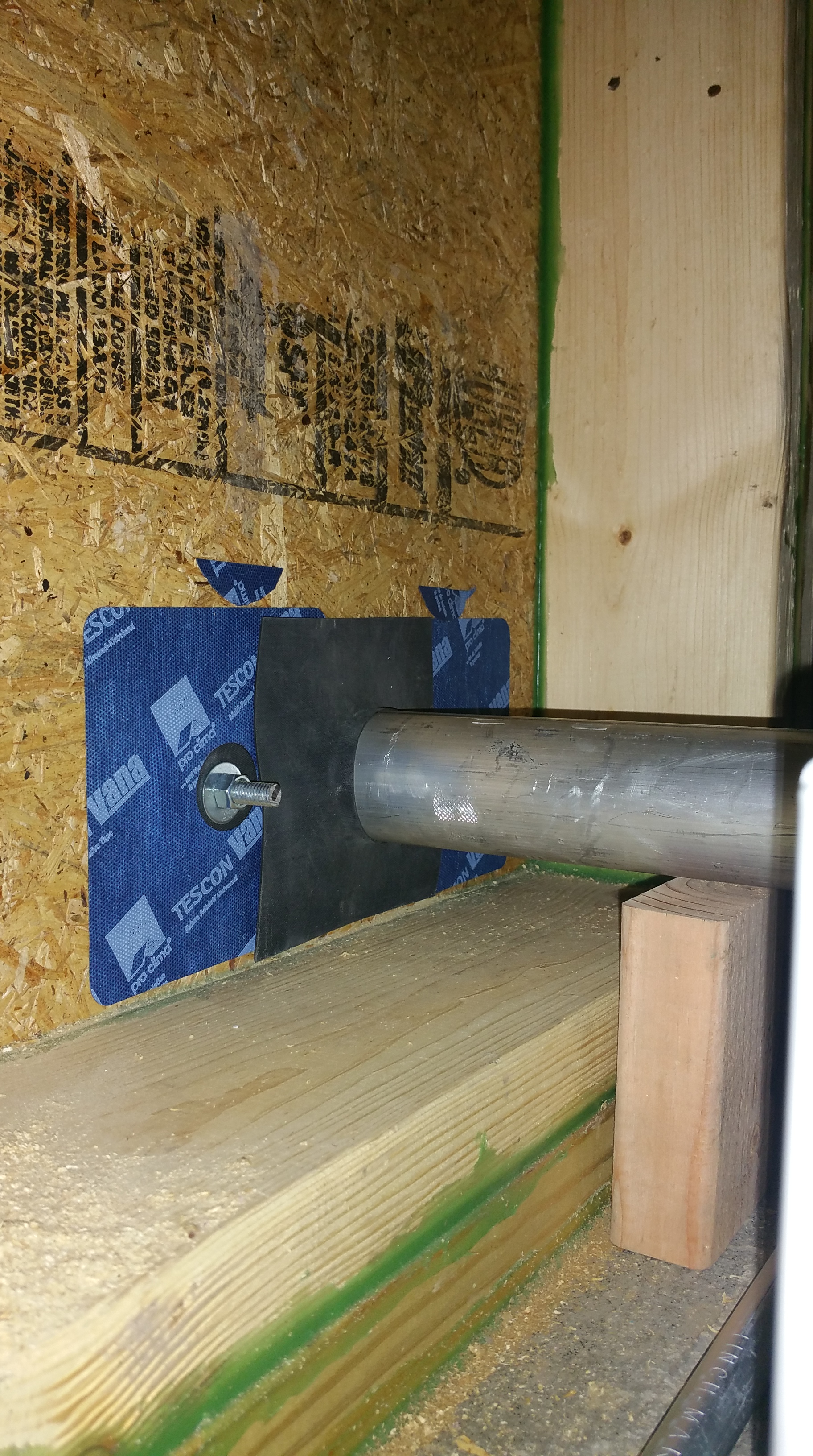
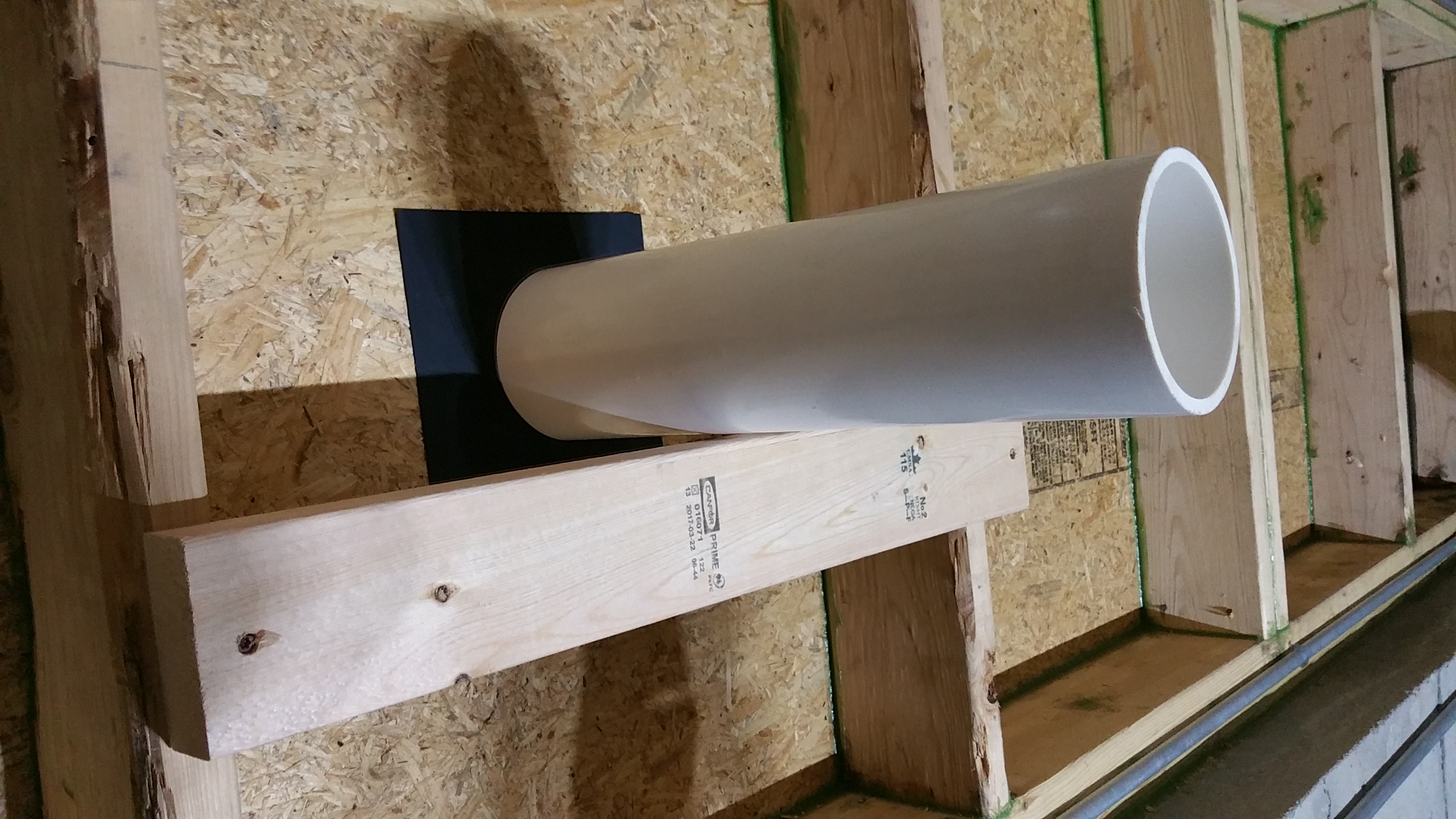
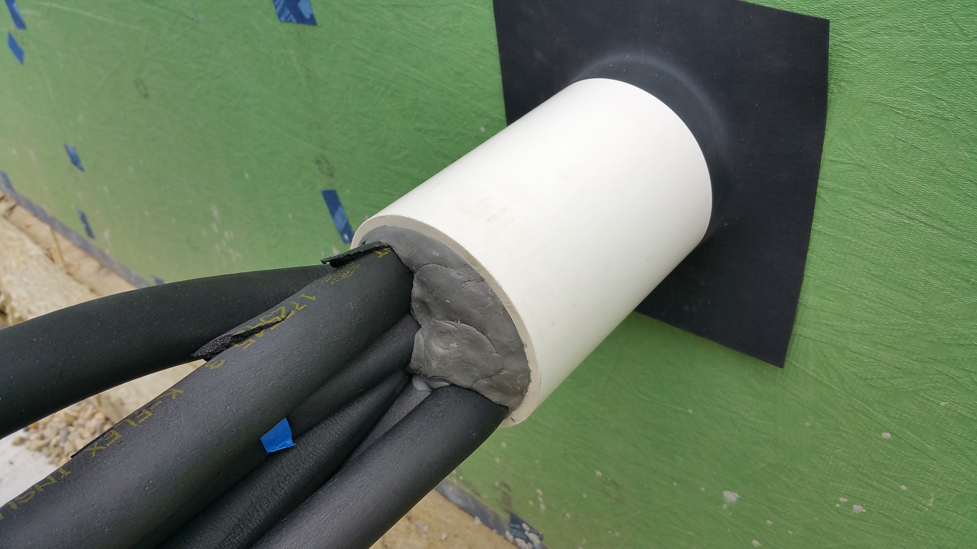
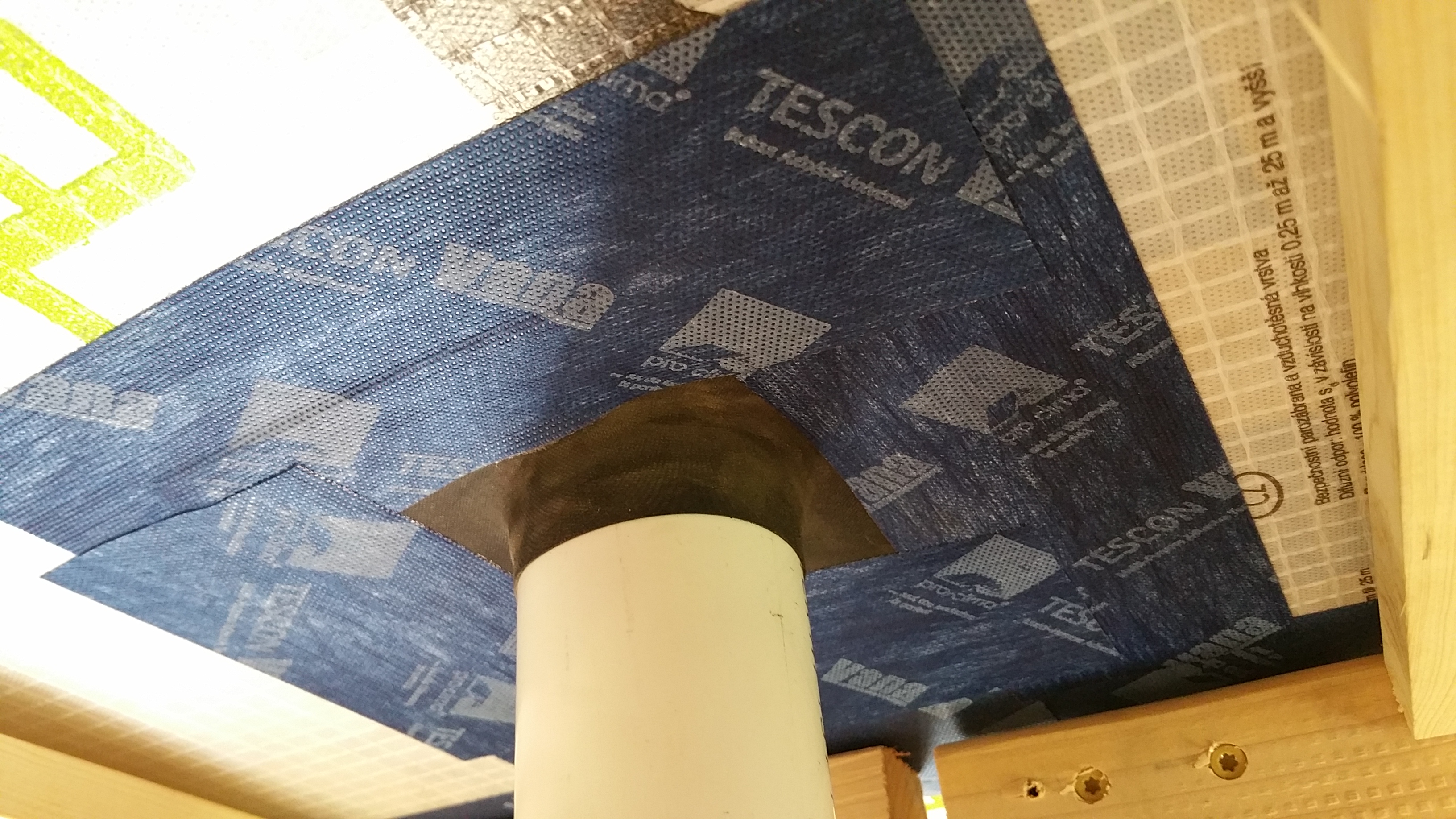
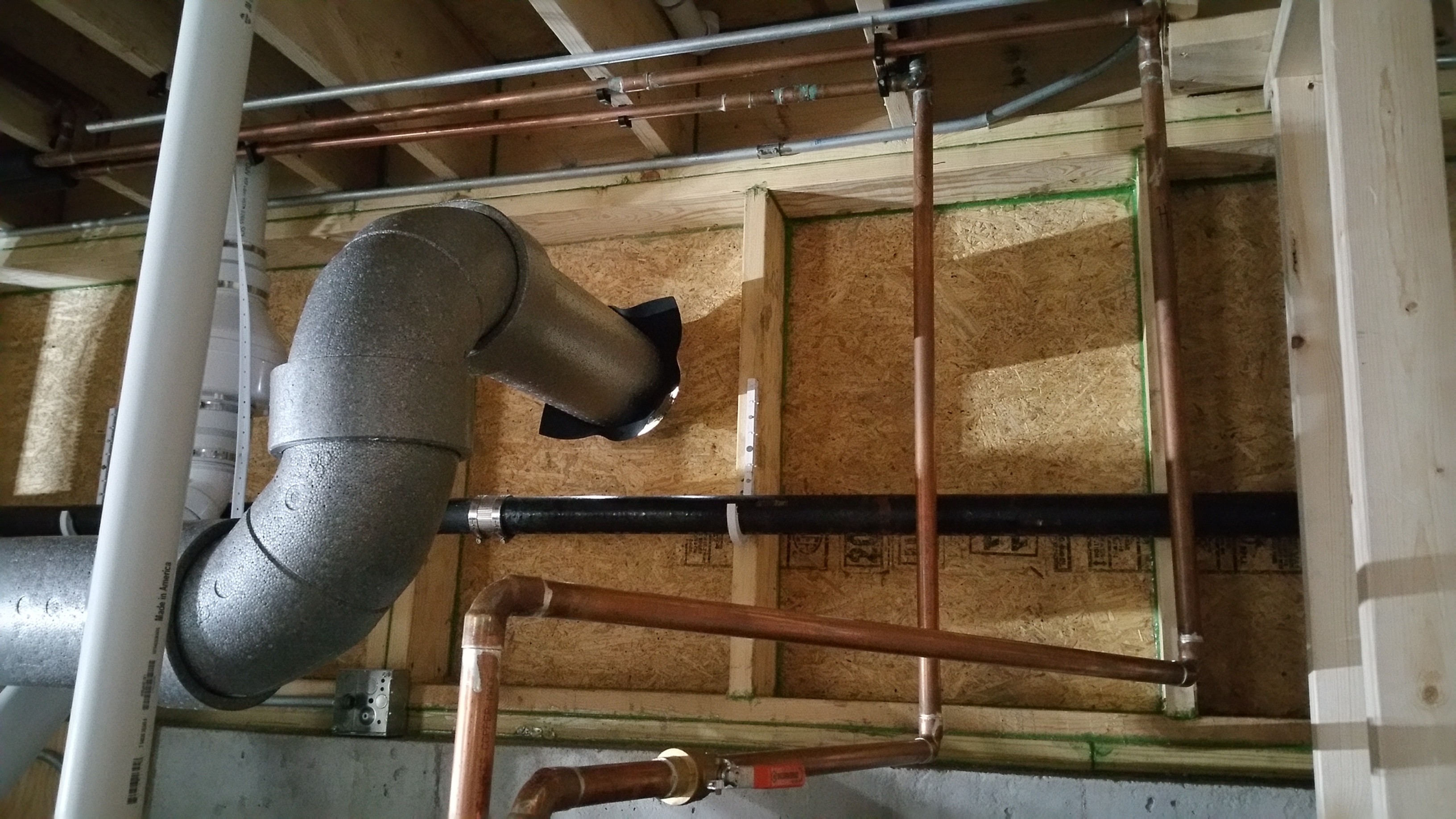
After discussing it with Mike from Compass Heating and Air, who did our ductless mini-split installation, we decided to use a 4″ section of PVC plumbing pipe as our “conduit” for running the refrigerant lines from the interior of the structure to the outside:
4″ PVC plumbing pipe for the refrigerant lines.
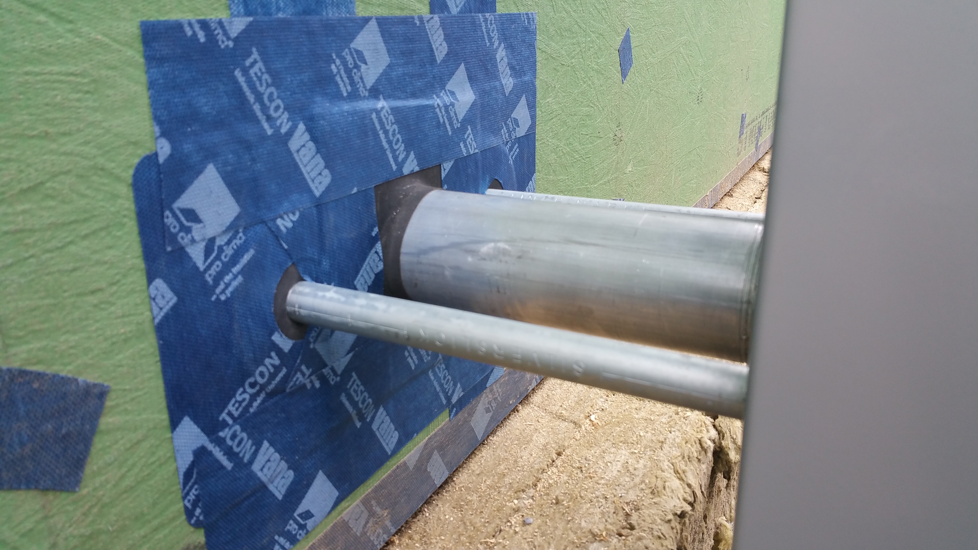
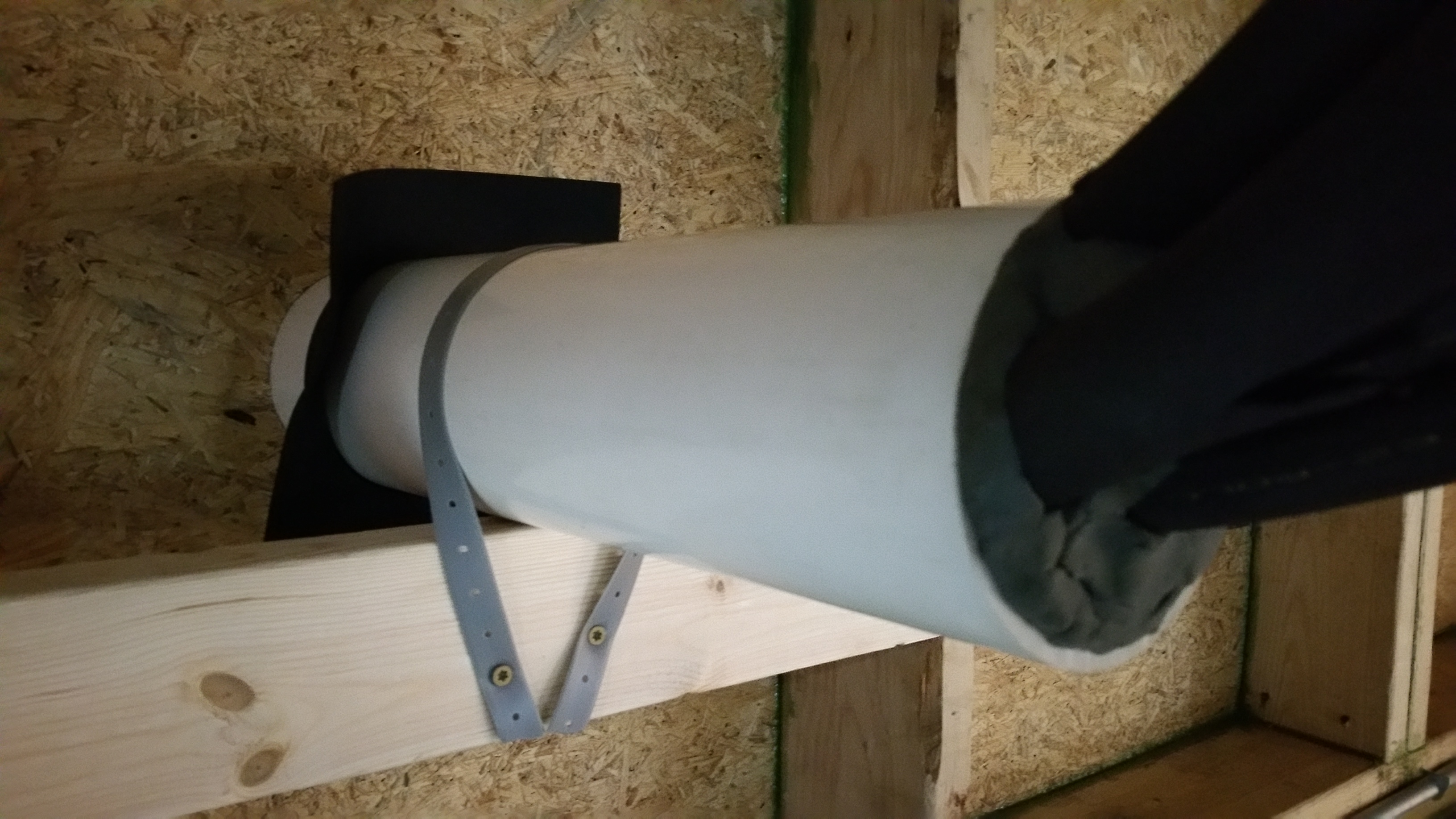
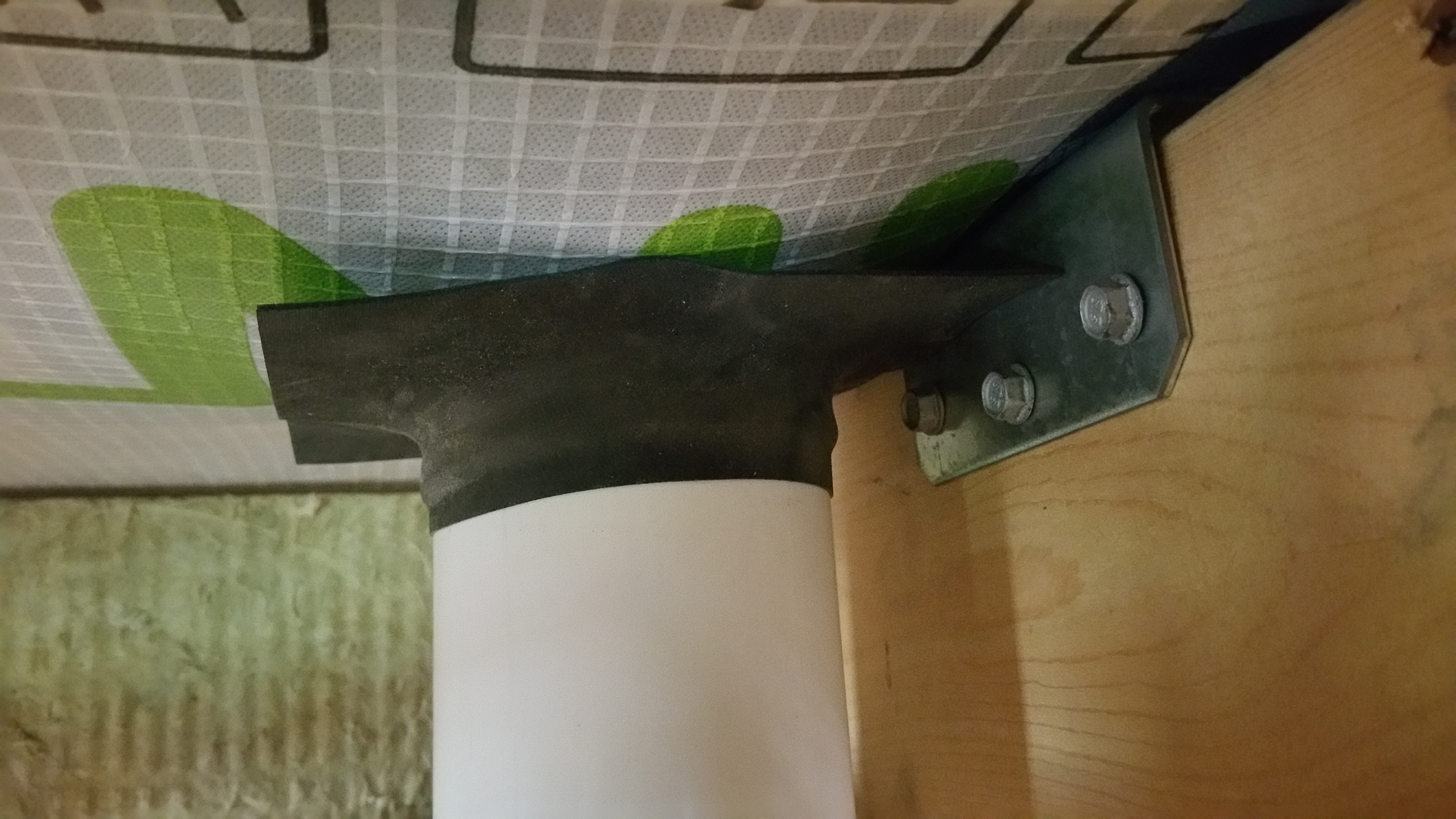
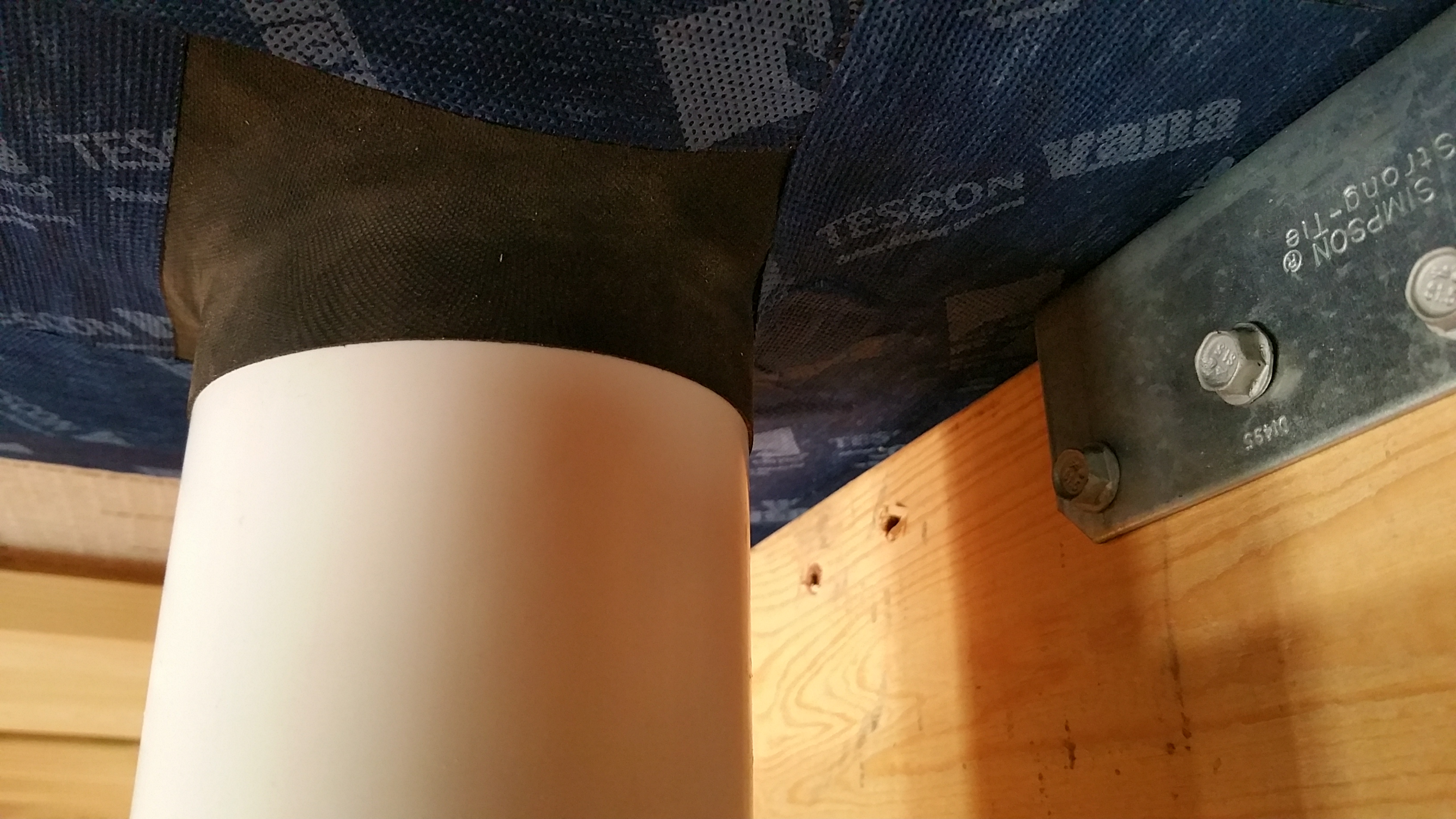
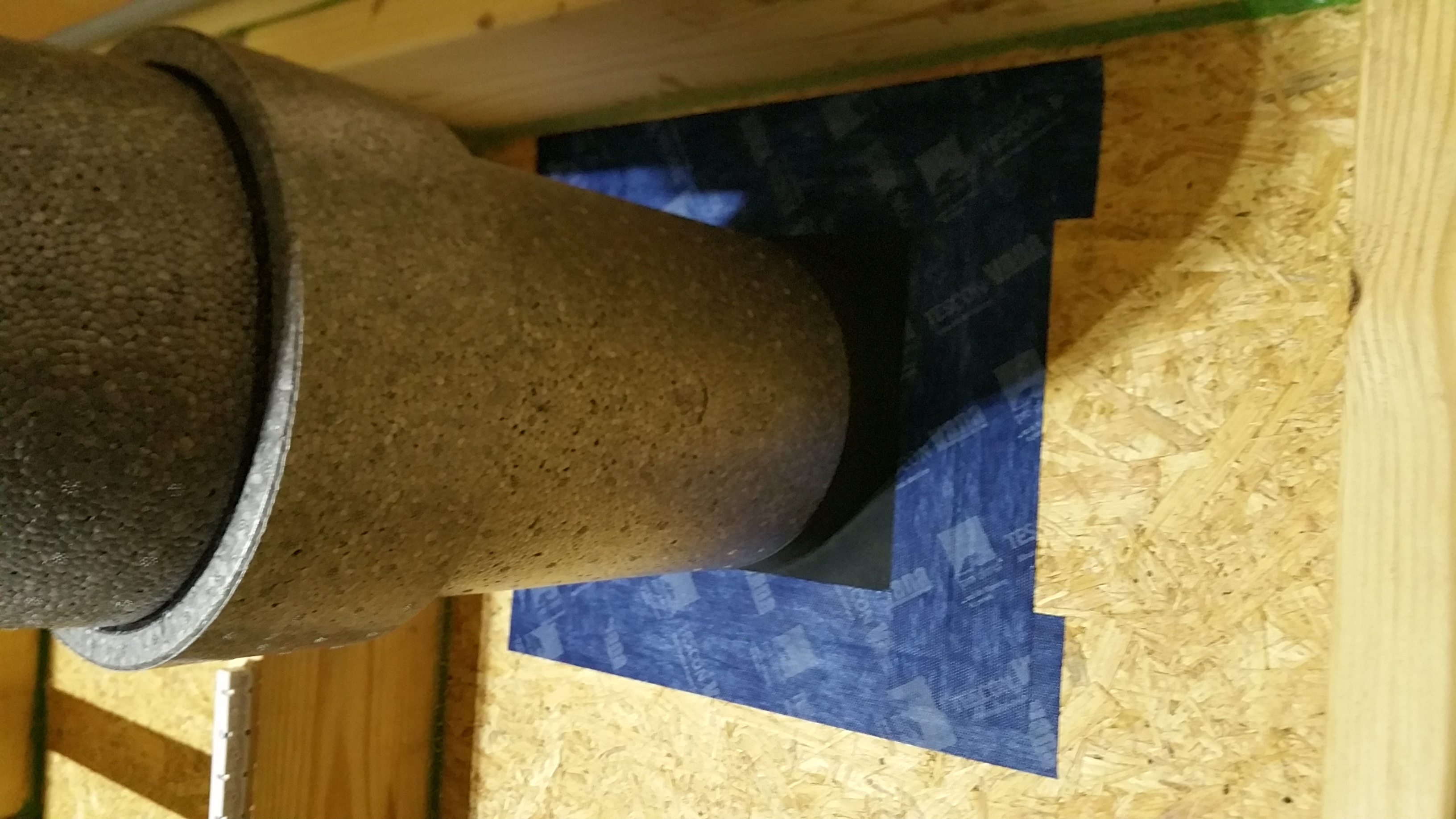
After the PVC was passed through the hole in the Zip, we added a 2×4 underneath it to give it some added stability, along with the usual gasket and tape for air sealing around the PVC pipe:
Before applying Tescon Vana around the Roflex gasket.
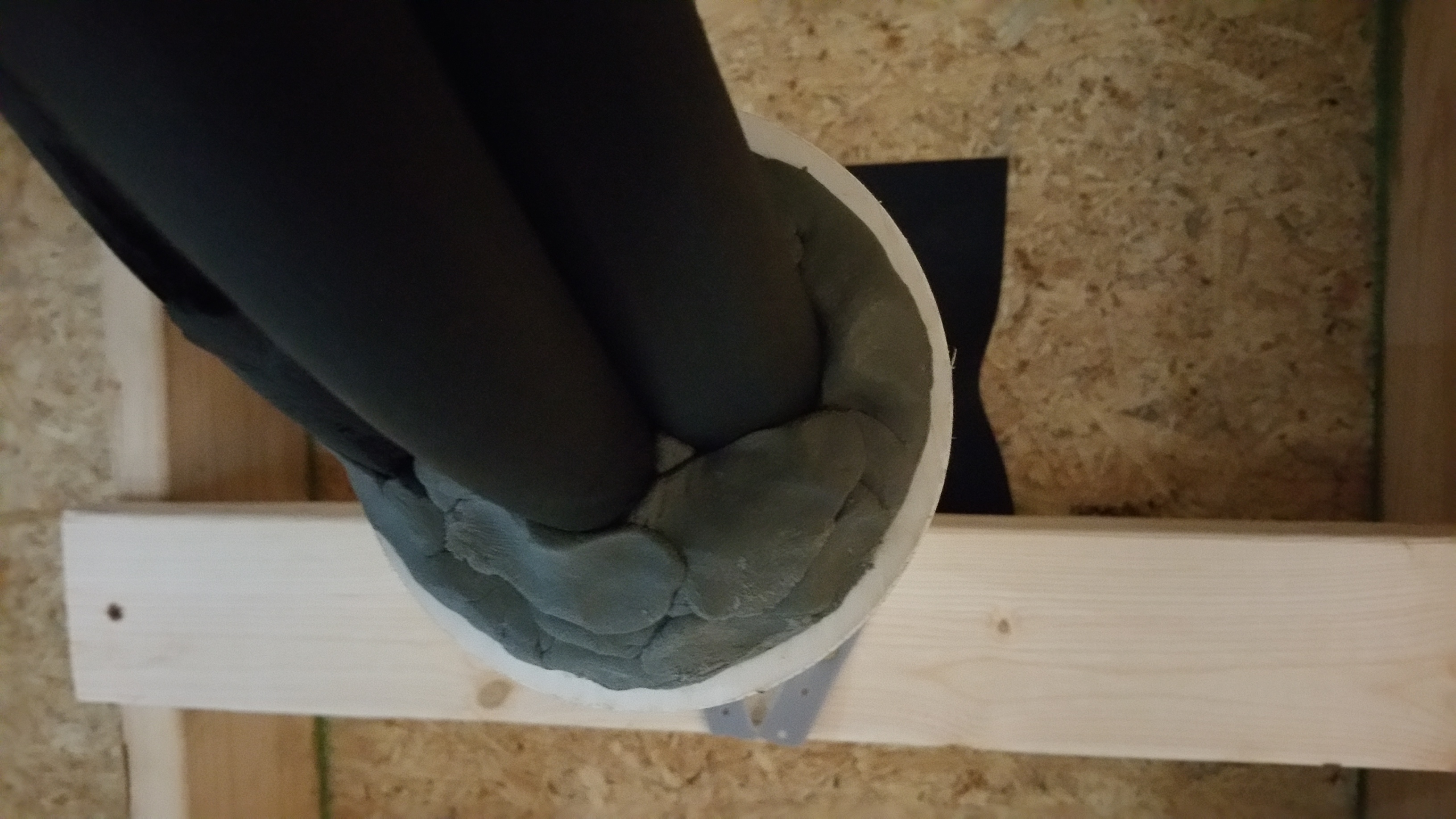
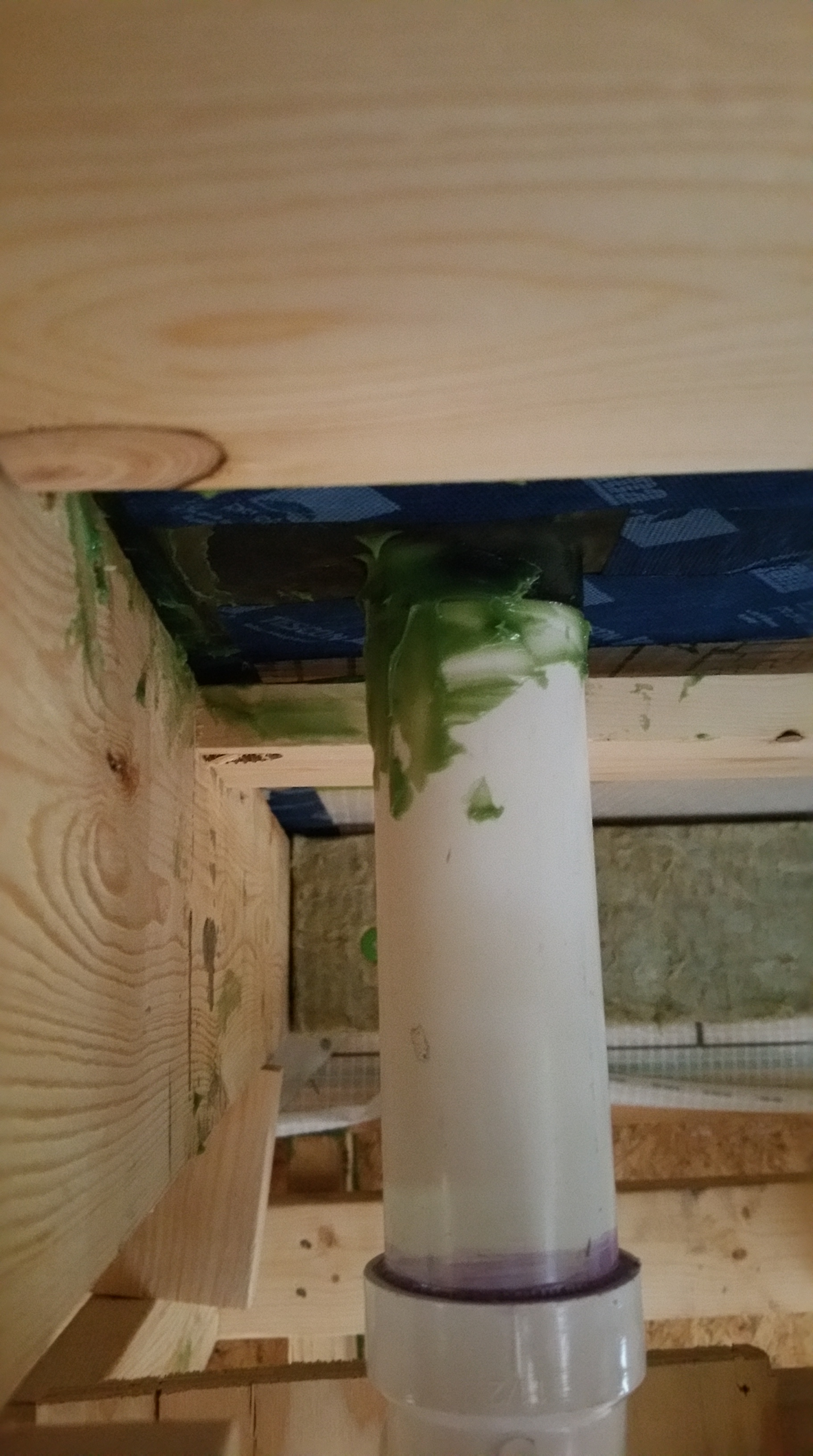
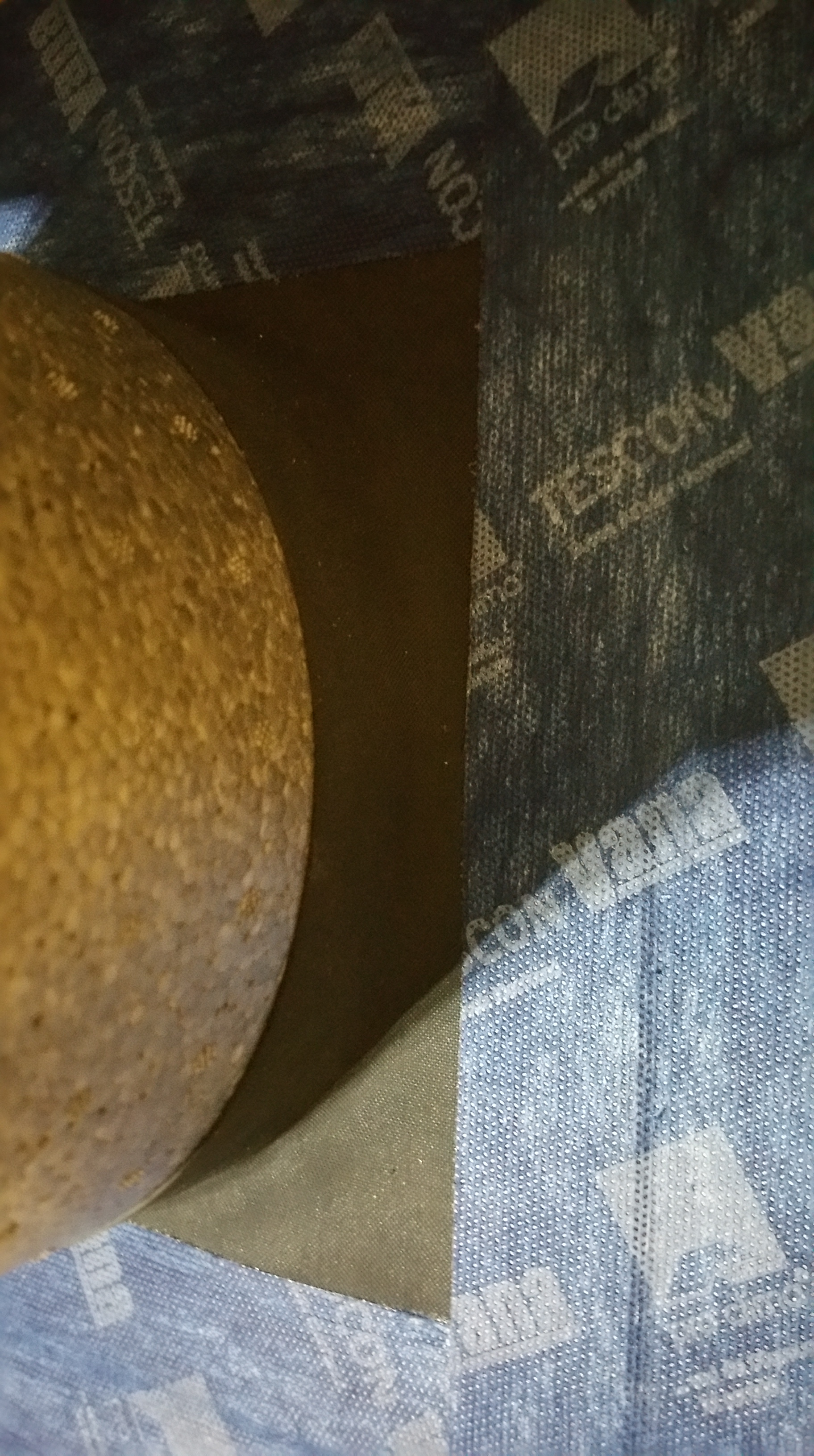
Once the refrigerant lines were passed through the PVC pipe, it was clear that some additional air sealing was required.
PVC pipe with refrigerant lines installed.
I filled the gaps around the refrigerant lines from the interior and exterior sides with duct seal. Before stuffing in the duct seal at either end of the PVC pipe, I added bits of Roxul Comfortboard 80 into the pipe to try and give added R-value to the interior of the PVC pipe (hoping to prevent any possible condensation from forming inside the pipe).
A real lifesaver when it comes to air sealing. Readily available at big box stores, or online at Amazon.
Duct seal proved especially helpful at air sealing multiple weak points in the structure —areas that would’ve been difficult or impossible to air seal with just tape, gaskets, or sealants:
Using duct seal to block off air from the interior side.
Another view of the PVC pipe with duct seal.
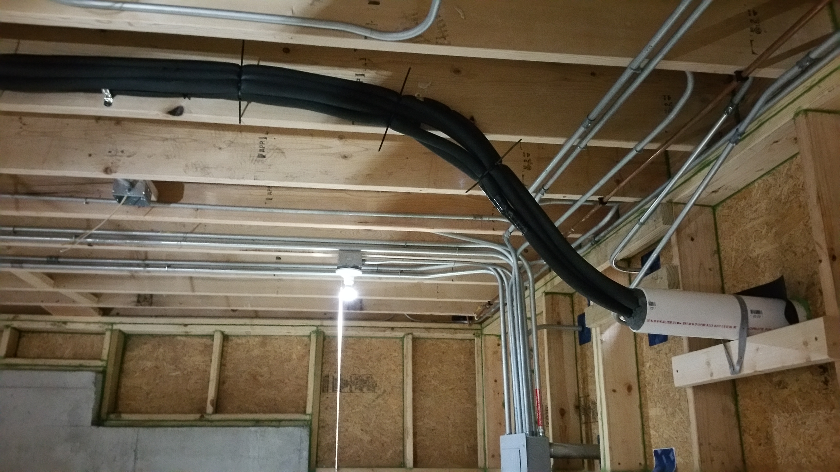
The refrigerant lines transitioning from the basement ceiling to the PVC pipe before leaving the structure.
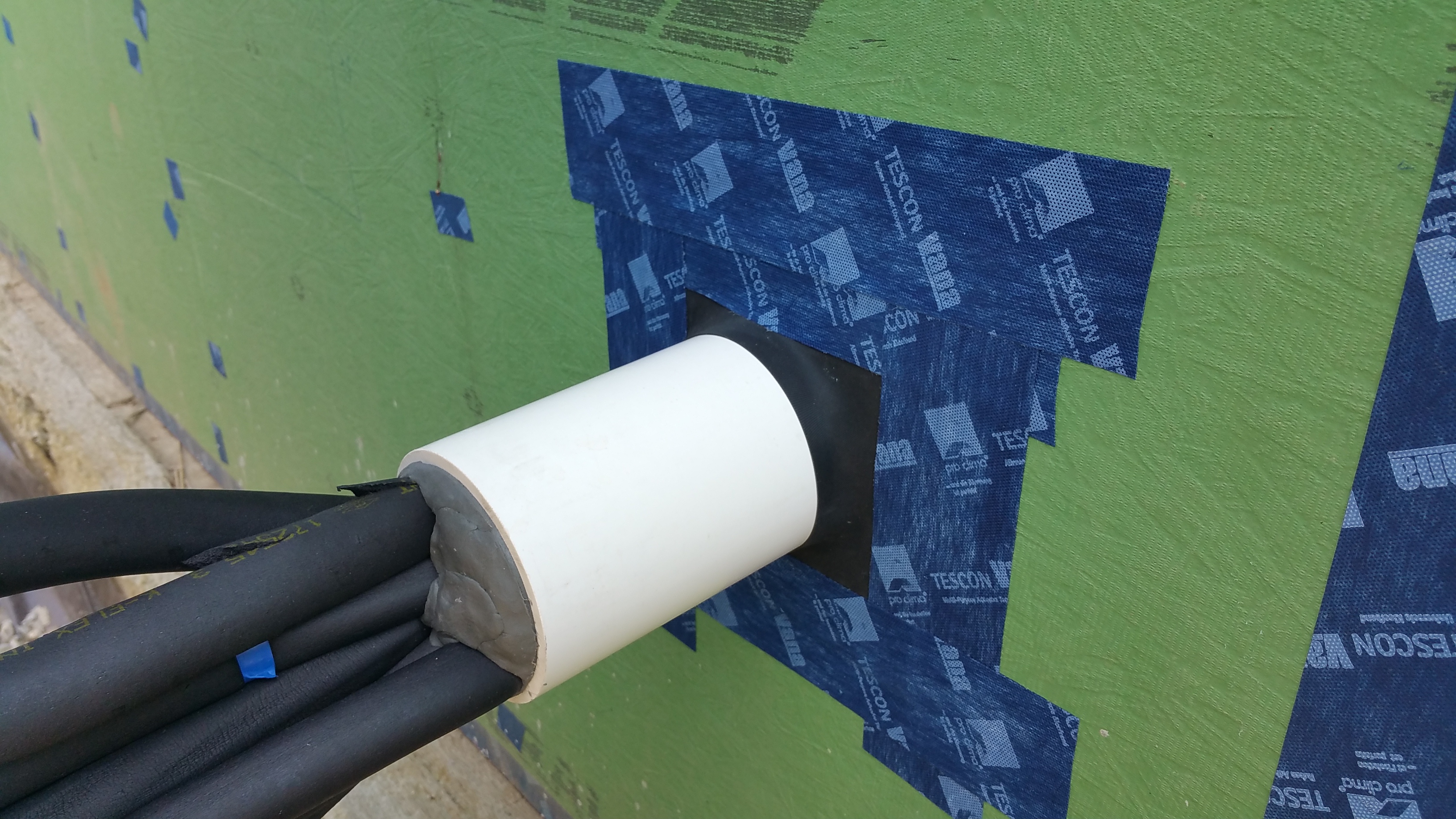
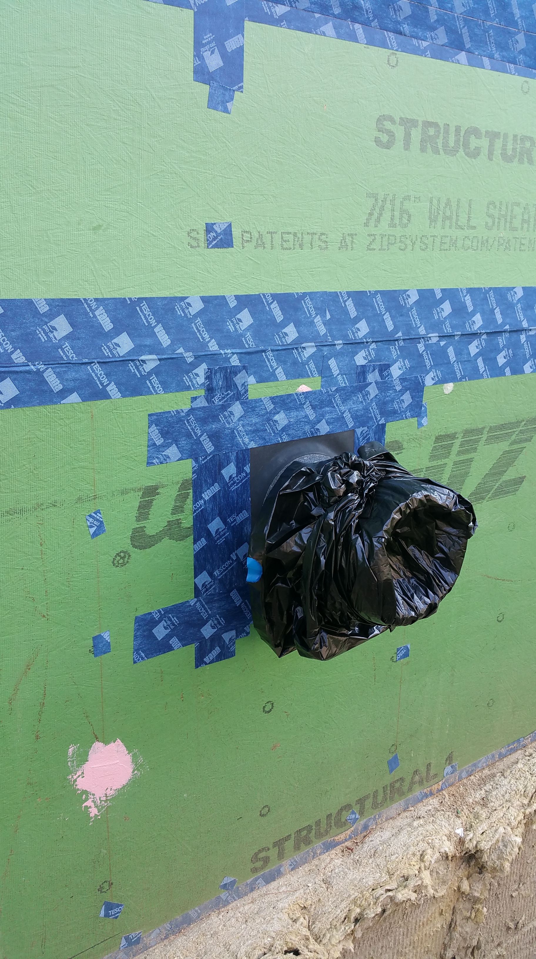
Once the interior was taken care of, I was able to address the exterior side of the PVC pipe:
Exterior view of the PVC pipe with heat pump refrigerant lines exiting the structure. Air sealed with a Roflex gasket and duct seal inside the pipe.
Again, note that the PVC pipe is extended out in preparation for the layers of exterior insulation, furring strips, and siding:
Same area after completing the air sealing with Tescon Vana tape.
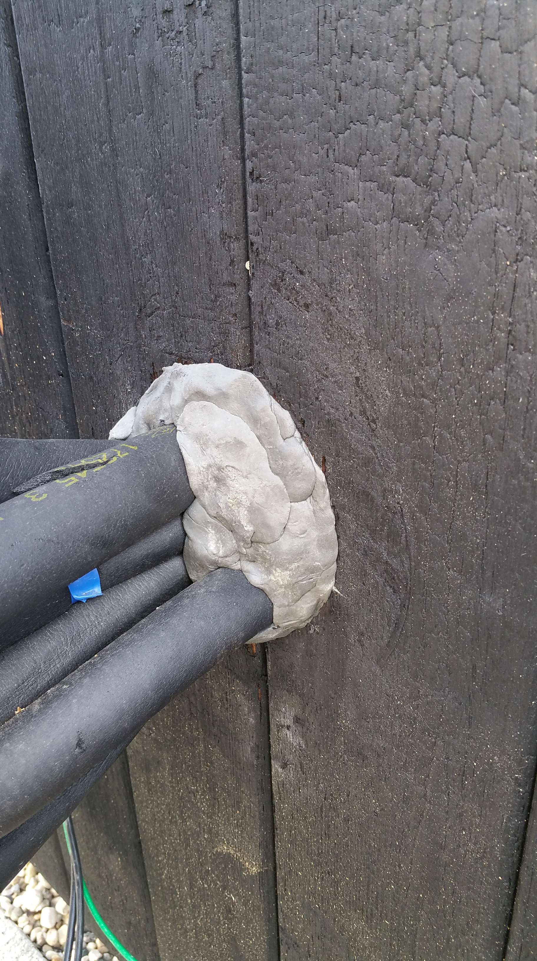
And here’s a view of the same area after the siding was installed (I’ll go into the many details regarding the installation of the exterior insulation, furring strips, and siding in a future post):
Air sealing for the refrigerant lines complete after the siding is installed.
Additional areas where the duct seal proved to be invaluable:
Exterior electrical boxes for lights and outlets.
Conduit for the water meter in the basement (only the interior is shown below, but the conduit was air sealed with duct seal on the exterior end as well):
And here’s the same conduit for the water meter as it leaves the house on the first floor:
Conduit for the water meter, air sealed on both sides of the Zip with the Roflex/Tescon Vana gasket.
I also had to address the disconnect boxes for our solar array and our heat pump. For instance, here’s our solar disconnect box when it’s open:
And here it is after removing the pull out switch, revealing an air leak:
Close-up of the conduit:
An even closer look:
And here it is after being air sealed with the duct seal:
I did the same air sealing for the Mitsubishi heat pump disconnect box:
Close-up of the conduit sealed with the duct seal:
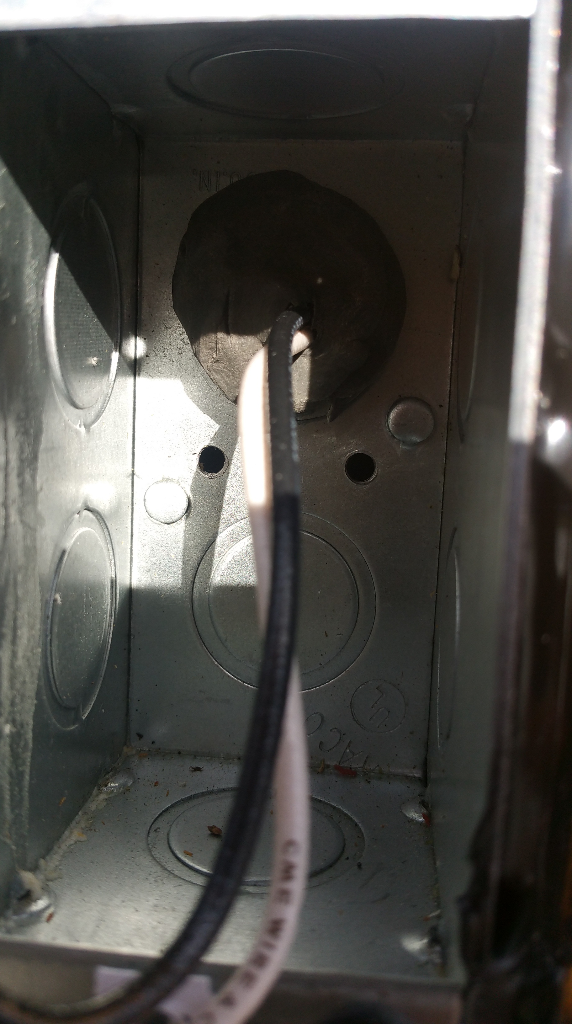
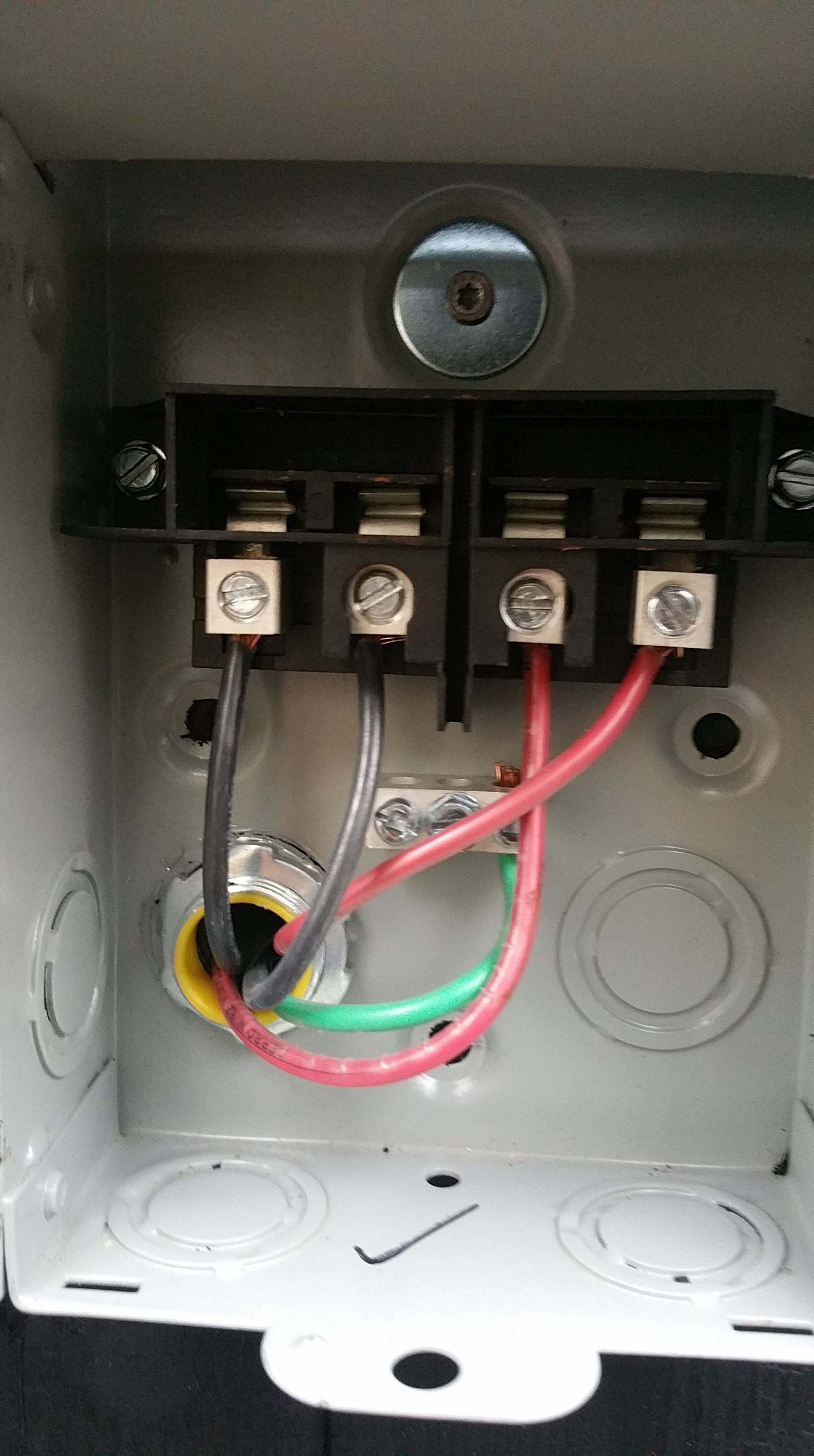
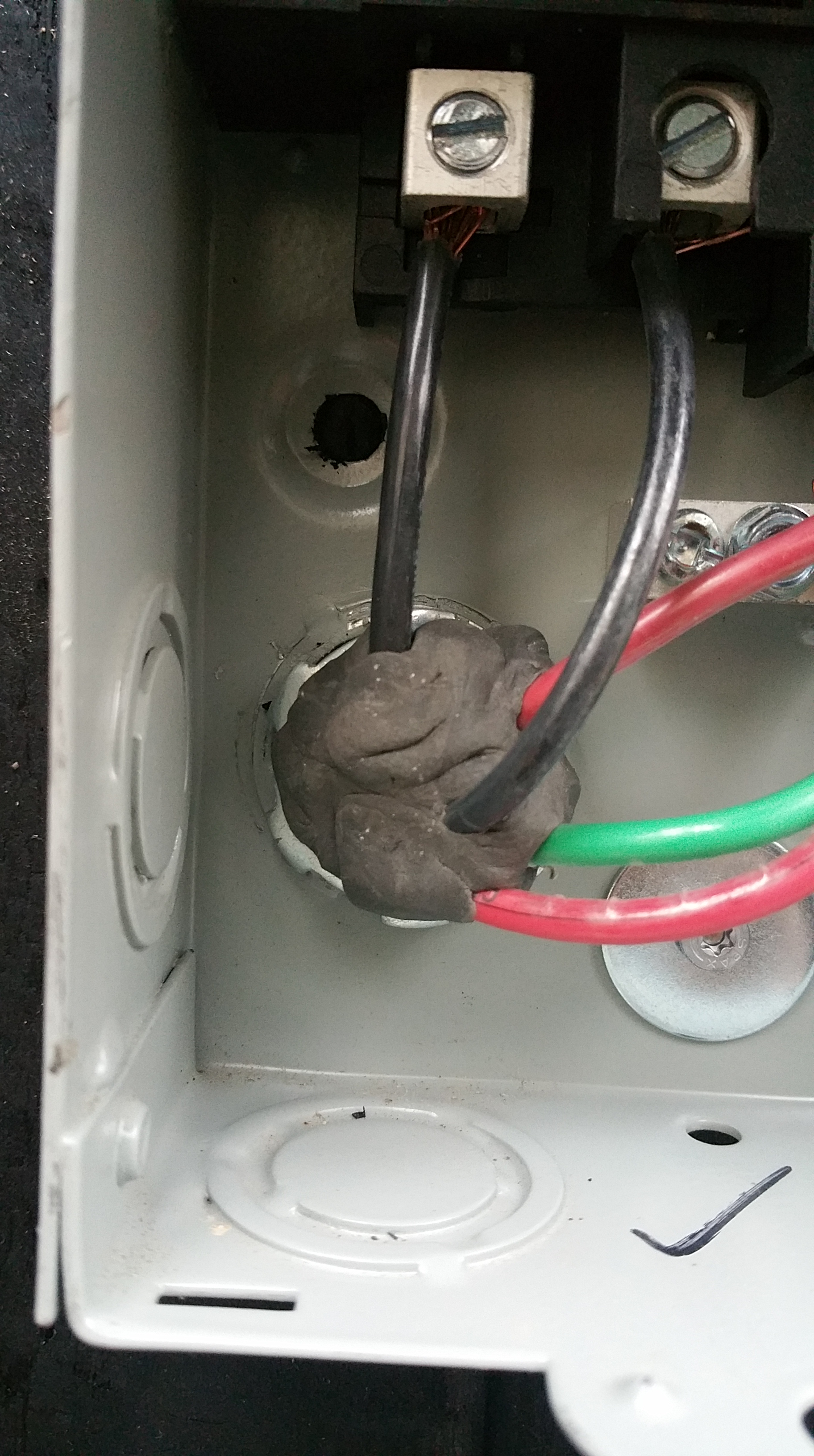
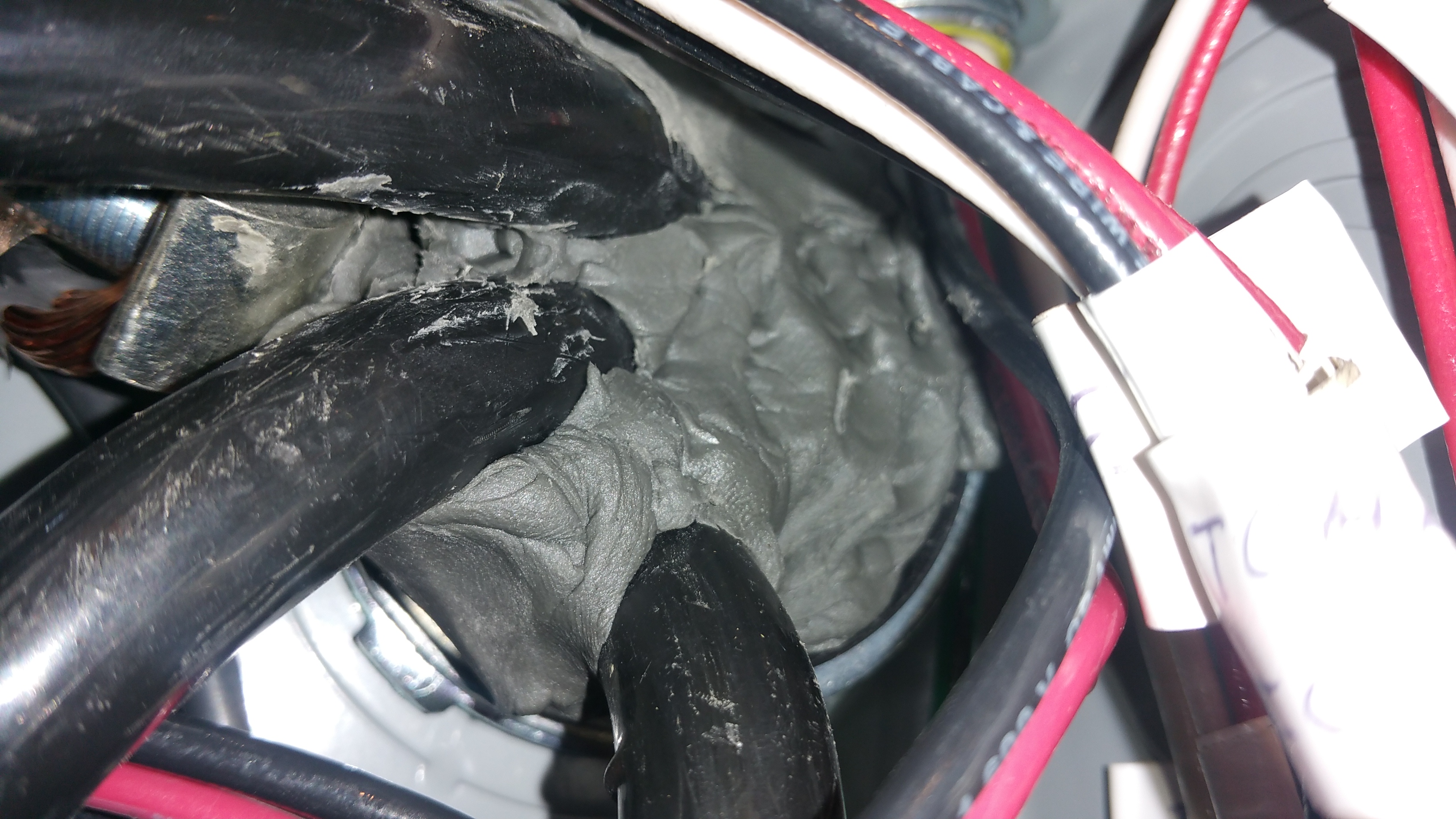
During my initial blower door test (more on that later), some air movement around the main panel in the basement was detected, so when the electrician came back we added duct seal to the main pipe entering the house (it had already been sealed from the exterior side with duct seal):
Close-up view of the main panel from the interior where lines first enter the structure.
Besides the penetrations in the Zip sheathing, there were other penetrations through the Intello (our air barrier on the ceiling) that had to be addressed as well. These areas were air sealed with the same set of products as the Zip.
For example, in addition to the conduit for solar through the Intello, we also had to air seal conduit for electric service to the attic (for a light and switch in the attic), in addition to the the penetrations for radon and plumbing waste vents, some of which are shown below:
Plumbing waste vent going into the attic.
Another view of this vent pipe after air sealing, this time from below:
Here is one of the vents that our first, incompetent plumber installed too close to one of the 2×6’s used to establish our service core:
Installed this close to framing makes air sealing the vent needlessly complicated and frustrating.
Here’s the same area after applying the Tescon Vana tape:
Below is another vent pipe incorrectly installed too close to a 2×6. This one was even more challenging to air seal properly. After the gasket and Tescon Vana, I added the green HF sealant as insurance against air leaks, both for now and in the future.
We also had to air seal the penetrations for our Zehnder Comfo-Air 350 ERV ventilation unit. I’ll go into the details of the actual installation later, but here are some photos of the penetrations through the Zip sheathing and how we addressed making them air tight:
First section of Comfo pipe going through the Zip sheathing.
The gray Zehnder Comfo pipe (for supply air stream) exiting the structure with a Roflex gasket.
Closer view of the Comfo pipe air sealed with a gasket and Tescon Vana tape.
An even closer view of this same area where pipe meets gasket and tape.
We followed the same process — Roflex gasket and Tescon Vana tape — for the exterior side of the Zehnder Comfo pipe:
Zehnder Comfo pipe installed, air sealed, and ready for commissioning.
And here’s a picture of both supply and exhaust pipes for the Zehnder:
Supply pipe in the background, exhaust in the foreground. The garbage bags keep out weather and animals until after the siding is up and the permanent covers can be installed.
During my initial blower door test some air movement around the sump pit was detected.
Sump pit lid sealed with duct seal, Roflex gasket with Tescon Vana, and the seam between the pit and lid sealed with Prosoco Air Dam.
The sump pump discharge pipe also needed to be air sealed on both sides of the Zip:
Sump discharge pipe sealed first with Prosoco Joint and Seam, then a Roflex gasket, before applying Tescon Vana tape around the gasket.
Some air movement around the ejector pit was also detected, so I used duct seal to try and block it.
Ejector pit air sealed with duct seal.
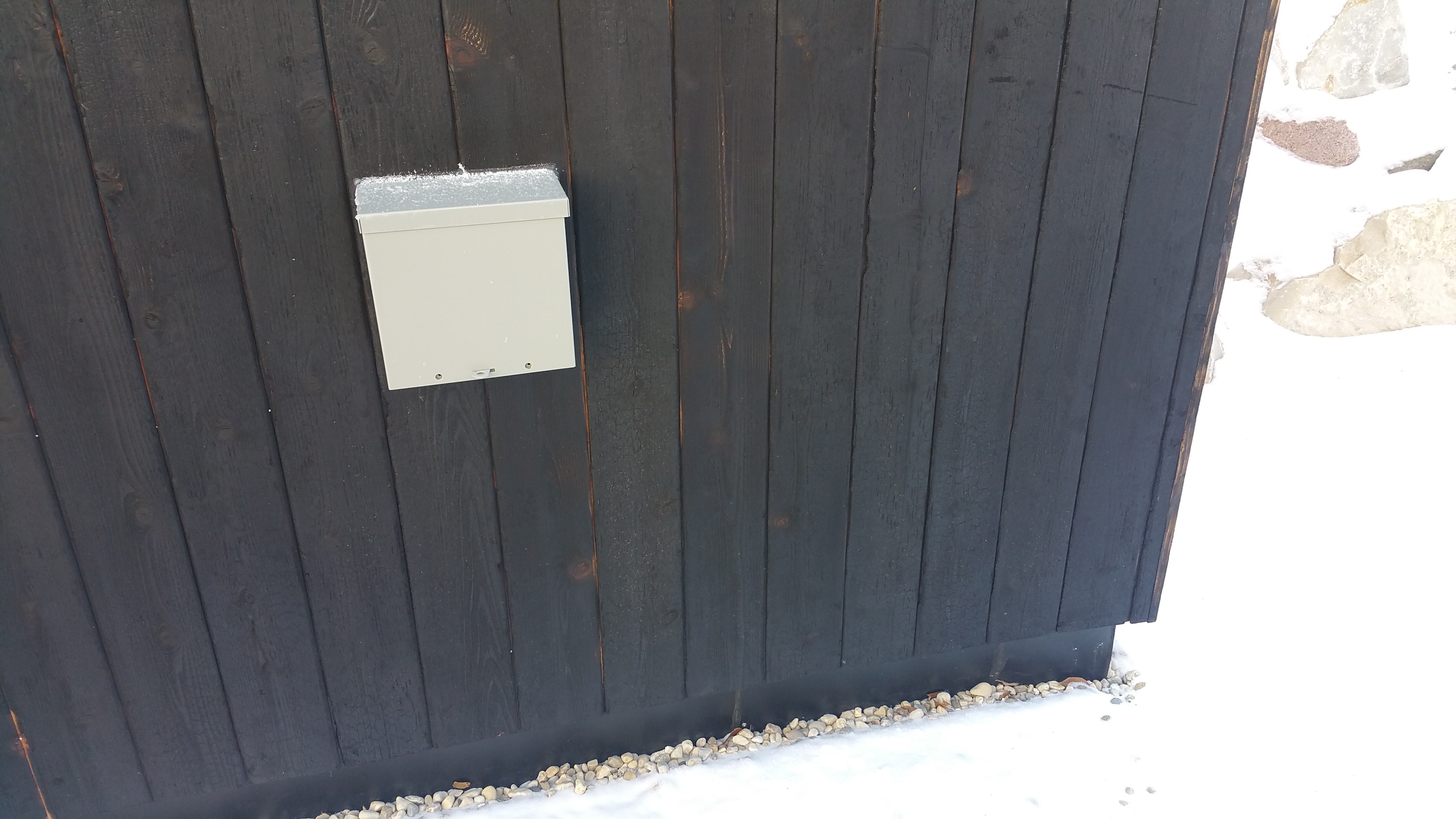
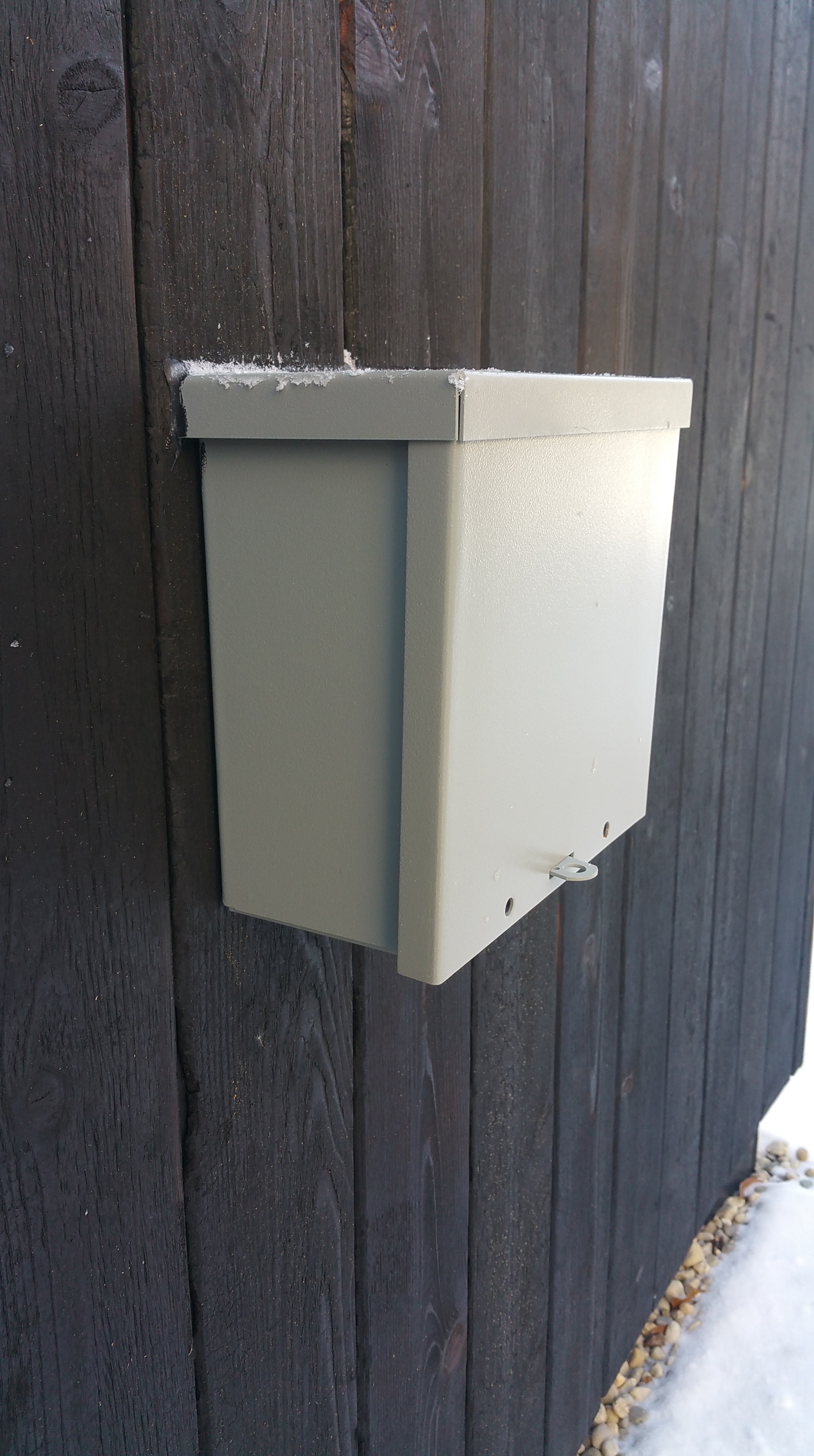
For low voltage — in our case, a cable TV/Internet connection — we found a utility box at Lowe’s (also available at Home Depot and Amazon), and combined it with conduit to transition from the exterior to the interior. The diameter of the conduit is large enough to allow wires for other utilities/services to pass through as well, if necessary, in the future.
Cable box installed after the siding went up.
An engineer from Comcast-Xfinity visited the site back in the summer, and he gave me the go-ahead for using this box/conduit set-up:
Closer view of the cable box.
The cable wire exiting the house through the conduit, which is air sealed with duct seal.
Cable wire on the interior of the house exiting through the Roxul insulation and Zip sheathing via the conduit and then air sealed from the interior with duct seal.
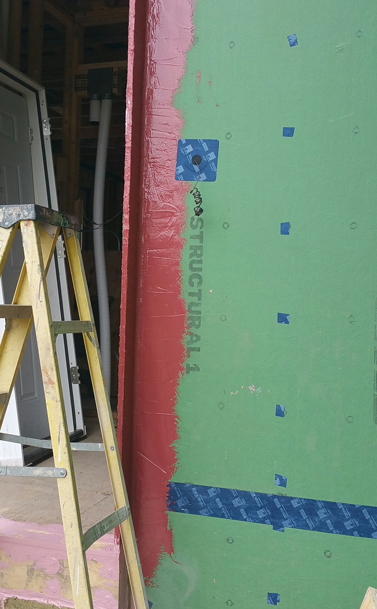
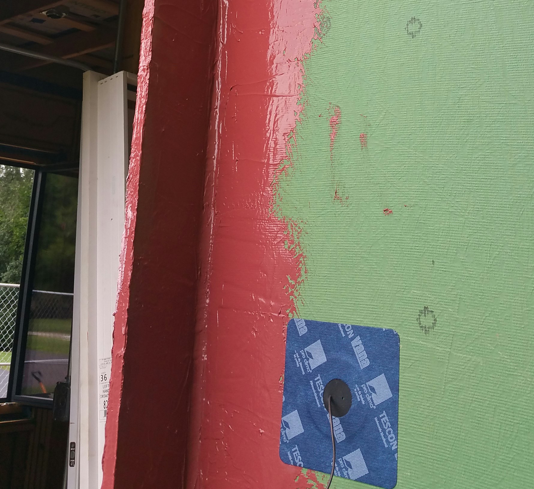
Even the wire for the doorbell was sealed with a gasket and tape:
When the weather warmed up I was able to experiment with the Prosoco R-Guard series of products (note the 3/4″ plywood door buck treated with Joint and Seam and Fast Flash). I’ll go into that more when I discuss prepping for the windows and doors later.
A closer view of the doorbell gasket.
Air sealing the penetrations was challenging at times, but also a lot of fun — always keeping in mind the goal of meeting the Passive House standard of 0.6 ACH@50 for our blower door test.
Hopefully this inventory of penetrations will prove helpful to someone in the planning stages of their own “air tight” build. It always helps seeing how other people do things — in particular, the strategies they employ and the specific products they use.
Seeing these real world examples of air sealing around the many penetrations in a structure will hopefully give others the confidence to come up with their own plan of attack for building an airtight structure.
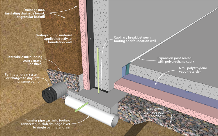
Following Passive House principles, we knew we were going to insulate and air seal our basement slab. As explained on the Passipedia website:
“The most important principle for energy efficient construction is a continuous insulating envelope all around the building… which minimises heat losses like a warm coat. In addition to the insulating envelope, there should also be an airtight layer… as most insulation materials are not airtight. Independently of the construction, materials or building technology, one rule is always applicable: both insulation and airtight layers need to be continuous.”
The illustration above also shows the “red pen test”, which is supposed to occur in the design phase of a project, when it’s much easier to address weaknesses or errors in the details of a design — not necessarily just for air sealing, it’s also effective when looking for points of potential water intrusion (e.g., this GBA article), or even to test the thermal layer for areas of thermal bridging. The basic idea is that if your layers aren’t continuous you’ll find yourself lifting your red pen, meaning it’s an area that needs to be addressed.
An effective way of thinking about a structure, utilized by high-performance builders, is to think in terms of 6 sides rather than just 4 when contemplating the details for air sealing and insulating: 4 walls, the attic/roof, and the basement (or frost-protected slab).
A similar approach to Passive House for building high-performance structures is adopted by advocates of The Pretty Good House concept, even if it’s less stringent, more open to interpretation, and tends to be more “rule of thumb” rather than energy model driven (e.g. PHPP or WUFI).
Based on our climate region, which is Zone 5, we decided we wanted to shoot for 16/20/40/60 for insulation R-values — the series of numbers represent R-values for under the basement slab/ the exterior foundation walls/ framed exterior walls/ and the attic (our attic R-value proved to be significantly higher than 60, but more on that later) — which is in the ballpark for both PGH and Passive House (here’s an excellent overall summary of the PH concept I recently came across: EcoCor).
Arguably, the “sweet spot” for how much insulation makes sense for these areas, even when adjusted for climate region, is still a topic for heated debate. Nevertheless, it’s important to keep in mind that the more simplethe form your structure takes — for example, 2-story cubes without basements —
the easier it is to achieve Passive House, or similar building standards, since it simplifies framing, air sealing, and limits the exterior surface area in ways that a single story ranch that is spread out and has all kinds of nooks and crannies does not (the difference also has serious ramifications for overall heating and cooling demand). Likewise, simple forms also make it easier to figure out how much insulation you need to reach a benchmark like Passive House or PGH. A simple form can also have durability implications.
Our R-values were based on a number of considerations: the construction drawings of our original builder, information made available by Hammer and Hand (in particular their Madrona House project), and articles on the Building Science Corporation (in particular: 1 and 2) and Green Building Advisor websites. These resources, all of which have proven to be indispensable at every stage of the build, have made our project possible.
In terms of the details around the slab and the foundation walls, this article from the DOE also proved to be especially helpful: Foundation Handbook
Illustration courtesy of: foundation handbook.ornl.gov
After considering various insulation choices (Wall Assembly), we decided to go with Roxul for under our slab, the exterior of our foundation, and our wall assembly (blown-in cellulose in the attic was the only significant deviation from the use of Roxul).
Here’s how the basement slab portion of our project progressed:
Roxul Comfortboard 80 (2″ + 2″)
To get to an R-value of 16 we used two layers of 2″ thick Roxul Comfortboard 80(R-4 per inch).
We installed each layer with staggered seams, although the Roxul representative I spoke with via email insisted that because the Roxul is so dimensionally stable this isn’t nearly as important as it would be with rigid foam insulation (the same holds true with a double layer of Comfortboard 80 on the exterior side of wall sheathing).
Putting down the 2 layers of Roxul Comfortboard 80 with help from the concrete guys.
The second layer of Roxul being installed.
Installing the Roxul around the rough-in bathroom pipes, sump, and ejector pits.
One of the many benefits of using Roxul is that the material wants to stick to itself, whether in batt or rigid board form. This makes for tighter joints between pieces, and even when cuts around obstructions are less than perfect it’s easy to fill in any gaps with torn apart pieces of Roxul (again, this holds true for both Comfortboard 80 and their version of batt insulation).
Stuffing bits of Roxul around the base of one of the steel columns.
Close-up of the Roxul installed around the roughed-in bath PVC pipes.
Another view of the 2-layers, mostly installed:
A Roxul rep told me to take into account a loss of R-1 due to the compressive pressure of the poured concrete, thus our R-16 for two layers of Roxul is, according to Roxul, really an R-15. Having installed the two layers myself, walked on it during and after installing the vapor barrier (see below), my guess is in some areas this loss in R-value is even greater than R-1.
Based on the comments quoted in a GBA article (Sub-Slab Mineral Wool), I would have to say my experience was exactly the same: in some areas the Roxul seemed to lose most, if not all, of its rigidity. I’ve also noticed while working with both the Comfortboard 80 and their batts that there seems to be a variation in the material from one piece to another and even bag to bag. Some pieces are very easy to cut (these pieces are noticeably stiffer), while other pieces seem “mushier” or lacking in rigidity — either under or over-cooked perhaps — making them more difficult to cut and work with. This seems like less of an issue for vertical applications (i.e. walls), while potentially troublesome for horizontal applications under a slab — especially if you’re depending on that R-4 per inch to meet the demands of energy modeling for a certification program like Passive House.
I’m glad we’ve been able to mostly avoid foam insulation in the build, but seeing the Roxul in a real world application does make me wonder if some kind of rigid foam might’ve given me a more consistent whole floor R-value. Going with a denser version of Roxul would’ve been another, more expensive, option as well (Comfortboard 110).
Stego Wrap
Once the two layers of Roxul were down, it was time to install the vapor barrier over the insulation. While the Roxul acts like a blanket, helping to maintain a consistent temperature in the basement, the vapor barrier helps to keep moisture and soil gases (mainly Radon as I understand it), at bay.
The product I’ve seen used in most Passive House, Pretty Good House, or equivalent projects, is Stego Wrap. Here are two videos detailing its installation and its benefits:
Another product I came across while researching options was Perminator.
Here’s a video detailing the use of the product:
In my area — the suburbs of Chicago — the closest supplier of Stego Wrap was HD Supply.
Starting around the rough-in bathroom pipes.
We used the 10 mil version of the Stego Wrap. The material is very durable and fairly hard to damage. Even when tears occurred, it was easy to patch with pieces of the Stego red tape, or a combination of a cut piece of Stego Wrap with pieces of the red tape.
Stego Wrap carried up the wall and taped to keep it in place during the pour.
Installing the two layers of Roxul on the basement floor was pretty straightforward, while installing the Stego Wrap was generally a pain in the ass. Maybe I was just tired, but I really didn’t enjoy installing it at all. For example, it was difficult to keep it tight to the walls, although I learned to leave it hanging fairly loose at floor-wall junctions, which definitely helped. Getting the first row straight, flat, and smooth was time consuming, and annoying, but it did make getting successive rows installed straight much easier.
Jesus helping me install the first row of Stego Wrap.
Making progress with the Stego Wrap.
Stego Wrap wth red Stego tape and a Roflex gasket from 475 HPBS.
The pipes after air sealing with EPDM gaskets and red Stego tape:
Once all the Stego was in place, we added a 1/2″ of rigid foam insulation at the floor-wall junction as a thermal break. I wanted to use Roxul Comfortboard 80 (their 1.25″ thick version) even for this, but time (Comfortboard 80 is still a special order item in my area, meaning it’s always about 2 weeks away from the time you place your order — hopefully this changes in the near future) and money made the foam an easier choice.
We kept the foam in place by running a bead of OSI sealant on the back of each section before pushing it up against the Stego Wrap. For the most part this seemed to work well.
Roxul, Stego Wrap, and foam installed.
Here’s a close-up of everything installed in a corner:
One of the real disappointments of installing the basement slab was seeing the concrete guys put down the welded wire mesh (typically noted as W.W.M. on construction drawings) — basically chicken wire with pointy ends (I exaggerate, but not by much).
If I could do it over again, I would look into using a concrete mix containing sufficient pieces of fiberglass, or some other alternative, so that using the welded wire mesh could be avoided altogether.
I was already familiar with the idea of fiberglass used in place of metal rebar in concrete forms, having experimented with decorative concrete last year and having seen videos like these:
I’m not sure why I didn’t think to ask for fiber reinforced concrete instead of the normal welded wire mesh — it was one detail that just got missed, unfortunately.
As the wire mesh went down, the guys could see how annoyed and concerned I was by the holes it was making in the Stego Wrap that one of them, Oscar, started helping me bend the pointy ends up. Once they were safely pointed up, I went around with the red tape to patch the many tiny holes in the Stego Wrap. Not a fun way to kill a couple of hours.
Why my architect or the concrete guys didn’t suggest a mix with fiberglass instead of the welded wire mesh is unclear. The reality with any green build, especially if you’re acting as GC, is you’re likely to be the only one who really cares about getting the many details right, especially if the architect and subcontractors have never built like this before — they were just doing what they always do.
A couple shots of the basement floor with the welded wire mesh in place:
A closer view with all the elements in place prior to the pour:
Concrete
Here’s various shots of the slab itself being poured:
It was necessary to cut a hole in the subfloor just inside the front door in order to get the concrete into the basement.
The guys starting at the back of the basement.
One corner complete.
Enrique completing the trowel finish.
Side of the garage kissed by the cement truck.
Close.
Really close.
Slab Edge
Once the slab was in place, I wasn’t quite sure how to deal with the edge along the perimeter. As usual when I get stuck on some detail, I asked a question on GBA:
Close-up of the wall-slab junction after cutting everything down flush with the floor.
Using the Prosoco Air Dam seemed like the best, and most straightforward, option. In addition, after considering various ways to cover this gap after the Air Dam was down between the wall and floor, and after priming and painting the basement walls, I realized the gap visually disappears for the most part, and really wasn’t worth thinking about.
Junction between wall and slab after using Air Dam and priming and painting the wall.
Close-up of Air Dam after primer and paint, at the wall-slab connection.
Another view of the slab – wall connection.
By not putting anything down to cover this gap, if the basement ever does experience water damage, it’s one less thing to remove and replace.
We thought about using the Zip sheathing as our air barrier on the ceiling, attaching it to the bottom of the roof trusses, something I had seen on other builds, but after learning about Intello we decided to use that instead:
Floris Keverling Buisman, from 475 High Performance Building Supply, did our WUFIanalysis for us, and he suggested the Intello would be a better fit for our project. The Intello is a smart vapor retarder, so it can expand and contract when it’s needed, and it’s obviously less physically demanding to install than the Zip sheathing.
Once the air sealing was complete around the top of our outside perimeter walls, and the insulation chutes had been installed, we were almost ready for the Intello. At the gable ends of the house, one last detail needed to be put in place, circled in red in the picture below:
2×6 on its side, circled in red.
By adding this 2×6 on its side, which is in the same plane as the bottom of the roof trusses, it makes it possible to carry the Intello over the transition from the ceiling (under the roof trusses) to the walls (top plates). This is one of those details that is hard to ‘see’ when in the planning, more abstract, and two dimensional phase of designing a structure.
Another view of the 2×6 lying flat in the same plane as the bottom of the roof truss (far left).
Once the trusses were placed on the top of the walls and you start picturing how the Intello will be attached to the ceiling, it becomes much more obvious that something in this space at the gable ends of the house is needed in order to accomplish the transition from the ceiling to the walls.
Marking progress: Ceiling ready for the Intello.
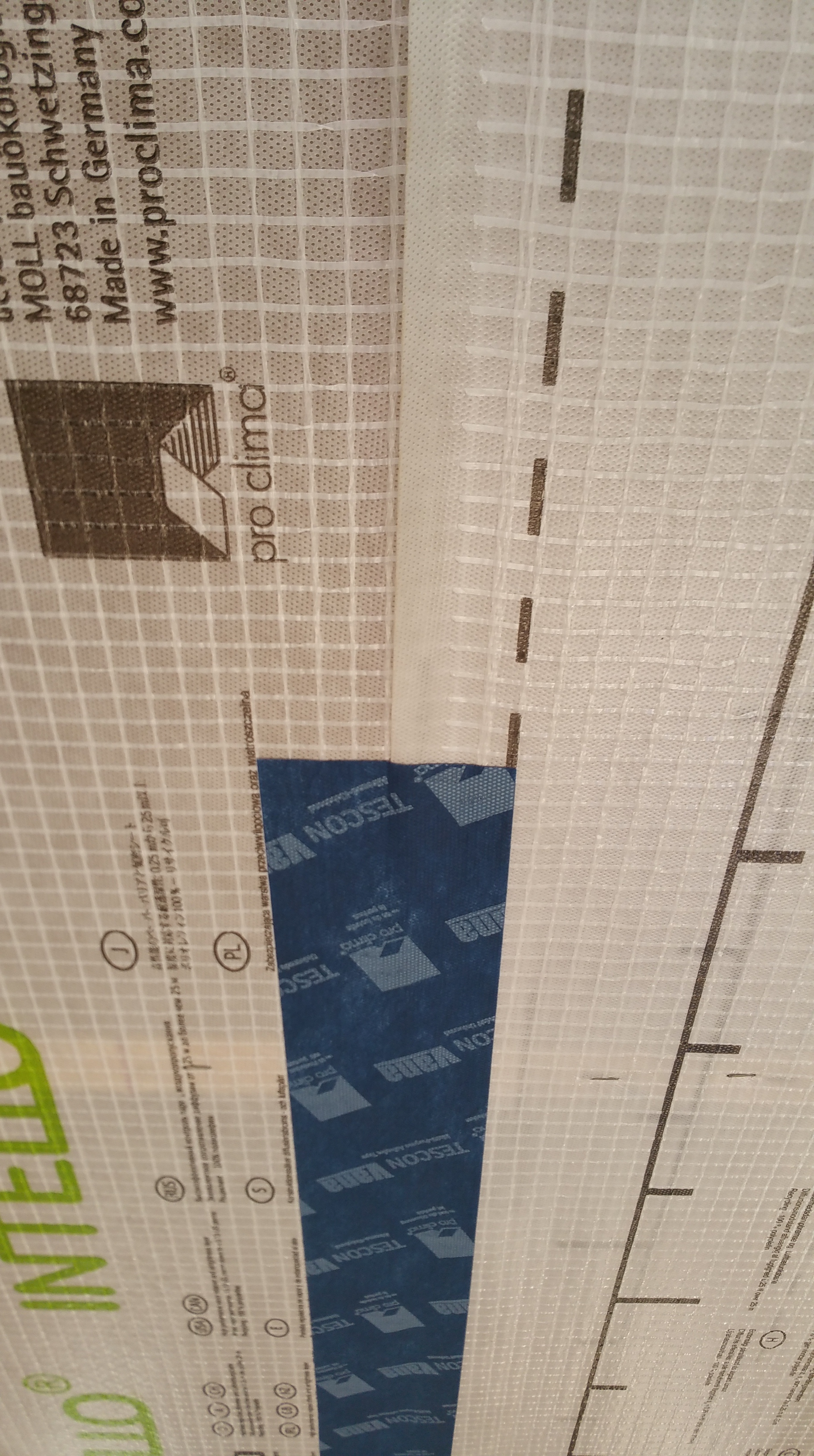
After reading about so many other projects that utilized Intello, it was exciting to unwrap the first box.
Big day: opening the first box of Intello.
The directions are pretty straightforward, and the product is relatively easy to install as long as you don’t have to do it alone.
Reading through the instructions one last time before starting.
I didn’t get a chance to touch and feel the product before ordering (always fun to do with any new product), so here are some close-ups of the Intello to give you some sense of what it’s like:
Front: shiny side of the Intello — this side will be facing the living space.
I was curious about its strength and tried to tear it with various objects, including the cut ends of 2×4’s and the brackets we eventually used to help establish our service core. The material is surprisingly tear resistant, but a utility knife, or a stray sharp edge will cut through it (as our first plumber proved to me with his careless actions — a story for another post).
Back: matte side of the Intello — this side will be facing the attic.
Having never used the Intello before, I decided to start small and began by experimenting with it in a corner. Getting the corners fully covered while getting the material to sit flat before applying the blue Tescon Vana tape proved to be the most challenging part of using the Intello.
Starting in a corner to get a feel for how the material will work.
Here’s two more pictures of the flat 2×6 helping to make the transition from the ceiling to the wall on the gable ends of the house:
In order to attach the Intello to the bottom of the roof trusses, we used the staple gun shown below. Loading it is kind of counter-intuitive (online reviews complain about it not working out of the box, but my guess is — like me — they were trying to load it improperly), but once I figured it out, it ended up working really well, almost never jamming, and it’s very comfortable to hold because it’s so lightweight. It should work with any standard air compressor. It was available on Amazon, and in Menards (a local big box store here in the Chicago suburbs).
The staple gun we used to attach the Intello to the underside of the roof trusses.
We started with these staples:
But we ended up going with these instead:
They seemed to grab better (presumably the sharp ends make a difference), and they sit flatter on a more consistent basis (less time having to go back, or stop, to hammer home proud staples flat).
As we rolled out the Intello, it took some practice to get it to sit taught and flat before stapling.
The dotted lines near the edges of the Intello help you keep the rows straight as you overlap two sheets and progress from one row to the next. The lines also make it easier to maintain a straight line with the Tescon Vana tape (don’t ask me when I realized this latter detail — too embarrassing to admit).
Follow the dotted line…
We checked our initial row from above in the attic:
View from the attic as the first row is installed.
Working our way through the interior walls, especially the bathrooms, was more time consuming and took more effort (I grew to hate those interior bathroom walls — first the Intello, then the service core details described below), but once we were out in the open the Intello was fairly easy to install.
First three rows of Intello as they approach the basement stairwell. Note the insulation chutes in the b.g. in the attic — they took up so much time and effort, and now they slowly disappear (just like most important aspects of infrastructure).
View of the Intello from a corner of the attic — note the 2×6, far left, lying flat, that helps the Intello transition from the ceiling to the top of the walls.
Another view of the Intello from the attic after installation.
As Eduardo and Jesus rolled out sections of the Intello I followed, pulling on the Intello a little to help make it sit tight and flat before stapling it in place.
Eduardo and Jesus giving me a hand installing the Intello.
There were a couple of sections, some of the first ones we installed, that I managed to wrinkle (one, in particular, became problematic during our first blower door test — and, of course, it was in a tight spot around the bathroom shower area), but overall, the installation of the Intello went pretty well. Like most things you do for the first time, we got comfortable and good at it just as we were finishing up.
Eduardo and Jesus helping me finish up the main areas as a full moon makes the night sky glow outside in the background. It was a long day — longer still for Eduardo since Jesus was talkin’ trash and nonsense all day (they’re football teammates). Needless to say, Eduardo has the patience of a saint.
View of the Intello from the attic — offering up its 2001: A Space Odyssey glow.
After learning about a project on the 475HPBS website…
… we decided to use the Tescon Vana tape to cover the staples, as well as all the seams, in the Intello. I have no idea what actual impact covering the staples has on air tightness, but visually as you tape over the staples you can see how, if nothing else, it will help the staples resist pulling out under pressure from the eventual blown-in cellulose in the attic.
Even as the build progresses, it’s interesting how details like this pop up, making building “green” a never-ending process of learning something new — someone’s always coming up with a new product or a new way to do things better, faster, or less complicated — which makes the process itself very exciting.
OB — the Palatine High School legend — the man, the myth, helps me tape over the seams and staples in the Intello. One of the many jobs he’s been kind enough to help me get done. We’d be so far behind schedule without all of his help.
View from above what will be the basement stairwell while installing the Intello on the ceiling.
Almost finished installing the Intello — saved the hardest part for last.
This was a nice moment, being able to look back and see the Intello completely installed. It’s almost a shame that we have to cover it with drywall.
Intello installed and taped.
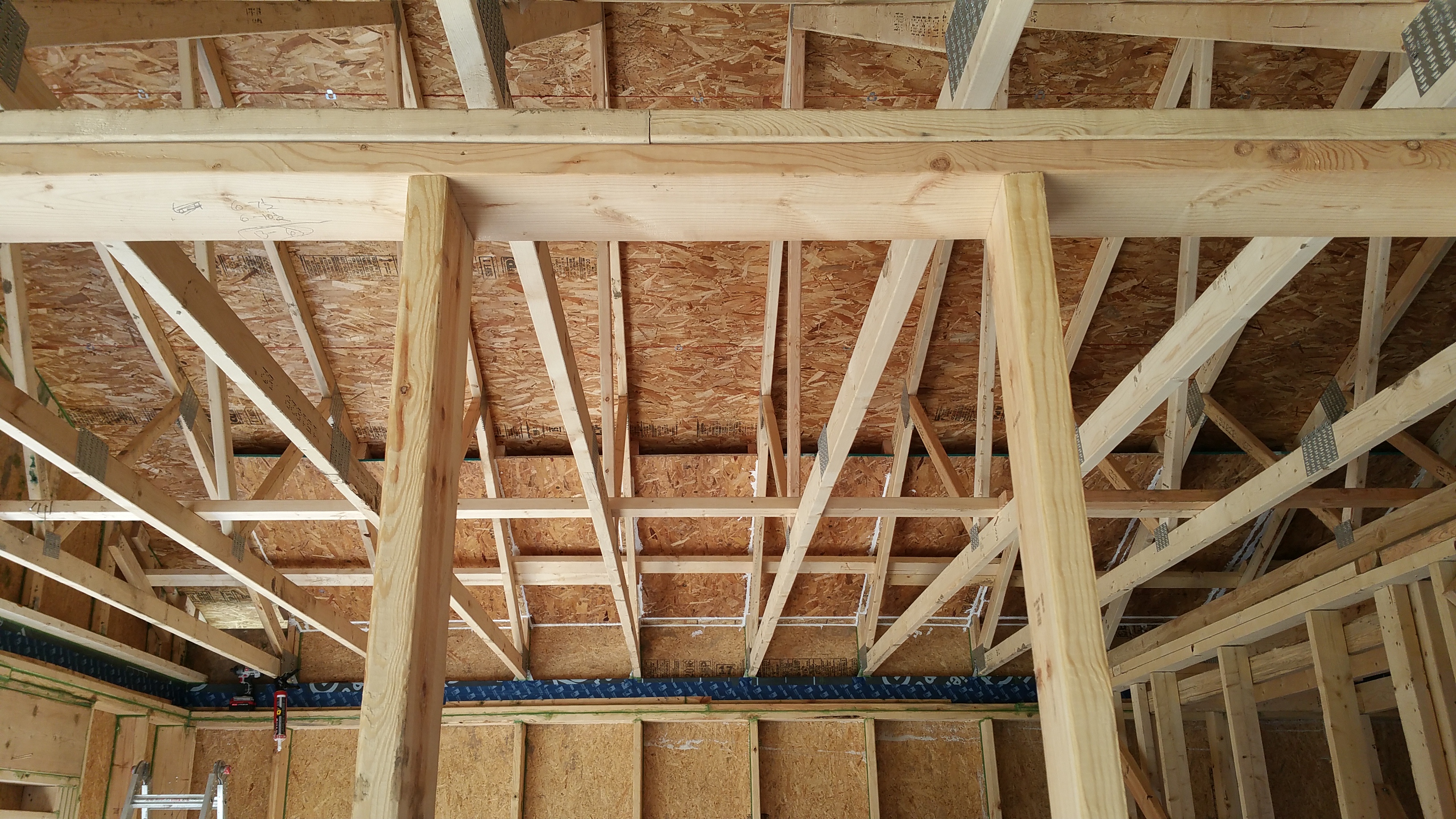
2×6 Service Core
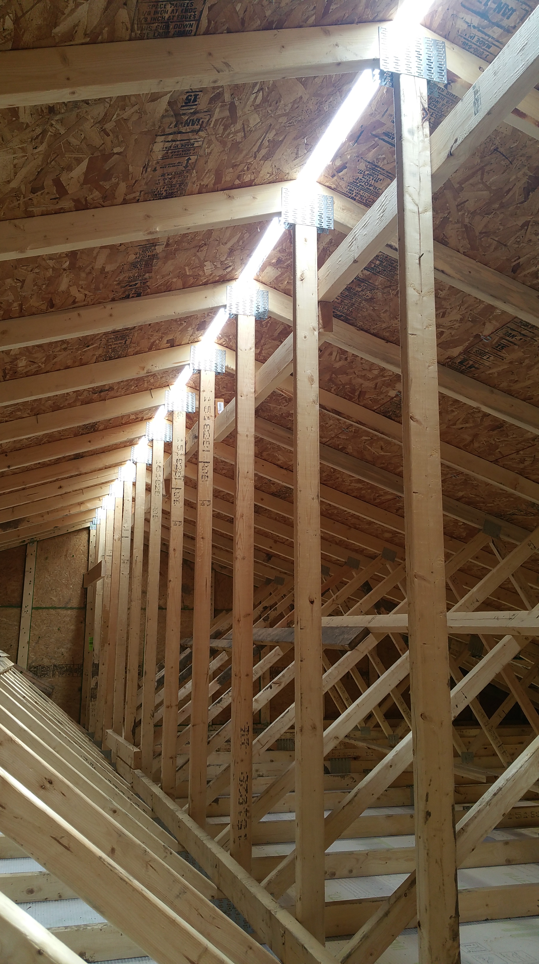
A design goal for the ceiling was to keep mechanicals, like HVAC and electric, on the conditioned side of the ceiling air barrier. By doing this, we avoid having to insulate any ductwork for HVAC, or air sealing and insulating around ceiling lights. In effect, we completely isolate the attic, making its sole purpose (apart from ventilating our “cold roof” assembly) holding our blown-in cellulose insulation (this set-up makes it much easier to air seal the ceiling and get the insulation right — at least based on the projects I’ve read about). In order to do this, we created a service chase, or service core, with 2×6’s:
First couple of 2×6’s going in.
In addition to serving as a space to safely pass mechanicals through, the only other job for the 2×6’s is to hold up the ceiling drywall. The roof trusses, directly above each 2×6, are still carrying the load of the roof and stabilizing the perimeter walls.
Simpson bracket and fasteners we used to attach the 2×6’s to the underside of the trusses.
Here’s what the 2×6’s looked like with their brackets once everything was installed.
Service core 2×6 with bracket and Simpson SDS bolts.
OB and my wife were invaluable as they helped me cut and install all the 2×6’s.
We installed the brackets first, before raising up each individual 2×6 to fit against the brackets.
Jesus helping me install the 2×6’s.
Since the brackets were directly attached underneath a roof truss, we were able to keep the 2×6’s fairly straight, even when an individual board itself was less than perfectly straight.
Brackets installed before the 2×6’s go up.
A feisty Robin kept trying to set up a nest on our partition wall (our windows and doors aren’t in yet). Apparently she believed we had created an elaborate bird house just for her. It took almost a week before she finally gave up — but not before starting multiple nests in multiple spots along the wall.
Robin making one of her many attempts at a nest on our partition wall.
Along the outside walls, at the top of the wall assembly, there was a gap that we utilized for maintaining continuous insulation. This meant there will be no break in our thermal layer going from the blown-in cellulose insulation in the attic to the monolithic layer of Roxul Comfortboard 80 (2″ + 2″) that will be on the exterior side of the Zip sheathing.
Adding Roxul at the top of our wall.
Close-up of the Roxul going in on top of the top plates.
Another view after the Roxul has been installed.
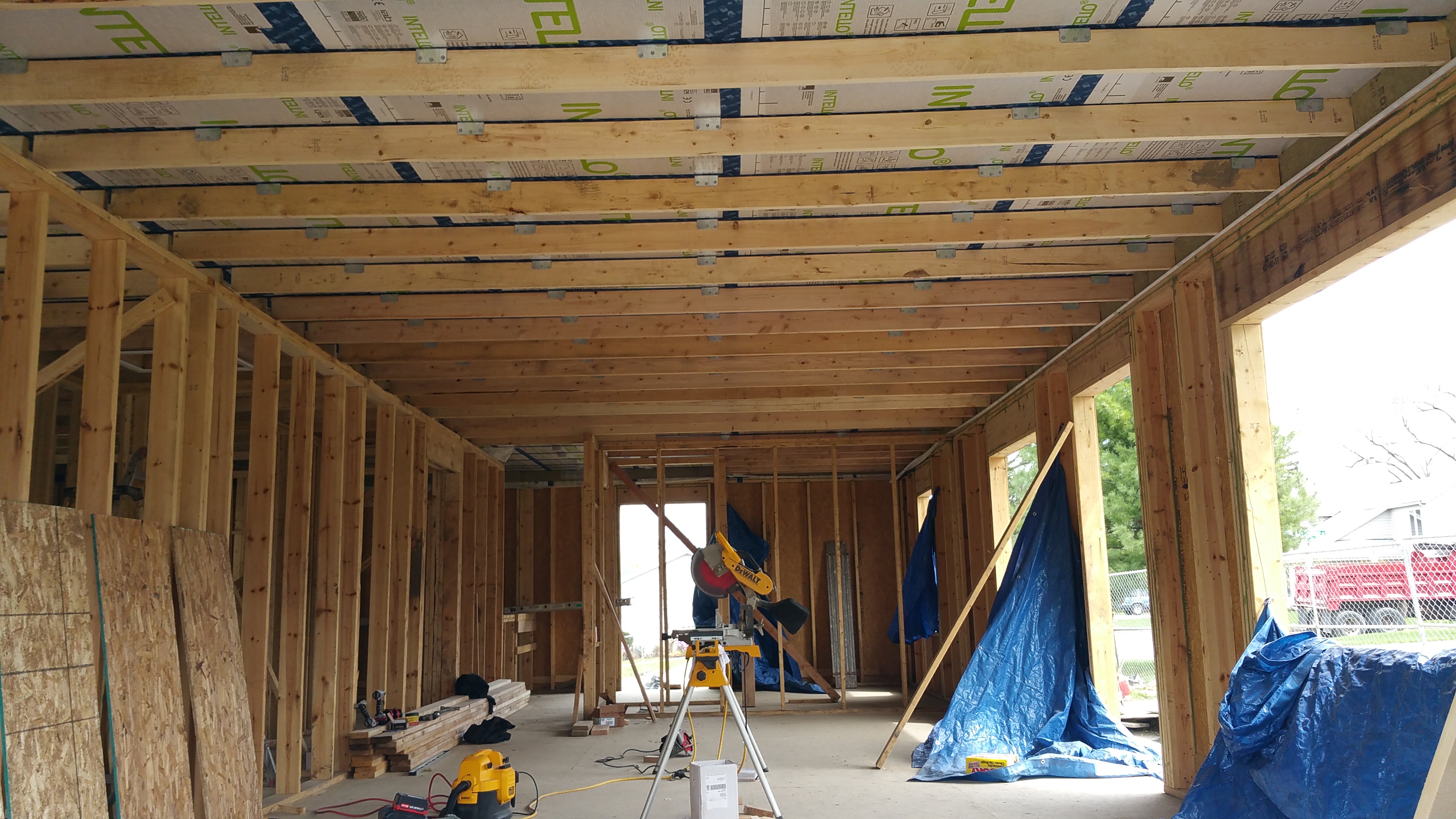
Marking further progress: Intello and 2×6’s installed.
Once the 2×6’s were up, we had to install our pieces of 1×4 in order to prevent the 24″ of blown-in cellulose that will be going into the attic from causing the Intello to sag.
The plans called for the 1×4’s to be installed right after the Intello but before the 2×6’s, which would have been a lot easier and quicker, but, unfortunately, the GC’s we fired installed the interior walls too high, making this impossible.
Here’s what it should’ve looked like if we could’ve done Intello and then the 1×4’s (photos courtesy of 475 HPBS) before installing the 2×6 service core:
Having no choice but to methodically cut each 1×4 to fit between each set of 2×6’s, OB was nice enough to help me get it done.
Installing the 1×4’s between the 2×6’s began with some experimentation:
Using L-brackets at first — it proved too time consuming and expensive.
After experimenting with a finish nailer (too easy to miss and penetrate the Intello), we eventually settled on Deckmate screws. It was definitely a laborious process, but eventually we got into a rhythm and got it done, although we wouldn’t recommend doing it this way — way too time consuming.
Completing our service core.
We tried to keep the 1×4’s about 16″ apart, which should prevent any significant sagging in the blown-in cellulose from occurring (I’ll post photos once the cellulose has been put in the attic).
A lot of blood, sweat, and tears have gone into completing this house.
Here’s some proof:
A decking screw got me.
In trying to avoid puncturing the Intello, I would hold a couple of fingers on the back side of the 2×6, feeling for any screws that would come through on a bad angle. A couple of times I drove a screw too quickly and paid the price.
View of the service core from the basement. Installing the 2×6’s and the 1×4’s also required walking the plank a few more times.
OB making my life easier as I work on the plank installing the 1×4’s.
Maintaining the Intello After Installation
Unfortunately, there was a delay in getting shingles on our roof, due in large part to our first disorganized and incompetent plumber (again, more on this later). Consequently, we were in the awkward position of having our ceiling air barrier and service core all set up but every time it rained we still had a leaking roof. In most areas it wasn’t a big deal, but in about a dozen spots rain would collect and, in some cases, cause a bulge in the Intello as it held up the weight of the captured water. To relieve and ultimately to avoid this pressure, I cut small slits in the Intello where the rain would consistently collect.
Slit in the Intello to allow rain water to fall through, marked with a red marker for easy identification later.
Once the shingles were finally on, I went back and found all of these slits and taped over them with the Tescon Vana.
Hole in the Intello covered and air sealed with the Tescon Vana tape.
We also found a couple of weak spots in the Intello as we installed it, and even later, during the installation of the service core. These spots were marked as well, and they, too, got covered with the Tescon Vana tape just for added insurance against air leakage.
Weak spot, or imperfection, in the Intello. This got covered with Tescon Vana as well.
After having to fire our GC’s, we couldn’t have kept the project going without the help of family and friends. As awful as some aspects of the build have been, it’s been heartwarming to find people willing to help us see the project through to the end (much more on this later).
Couple of Cheshire cats — clearly up to no good — helping us to keep the job site clean.
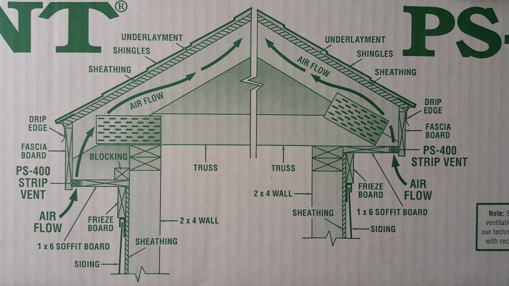
Our structure was designed with a “cold roof”, or ventilated roof assembly. By having continuous ventilation in our north and south soffits, with a ridge vent on the top of our roof, outdoor air can freely enter the soffits and exit out the roof’s ridge vent. The benefits of this set-up are explained in these comprehensive articles:
In order to make this kind of roof assembly work, insulation baffles or insulation chutes are necessary, especially if the attic is going to have any kind of significant amount of insulation, in particular blown-in insulation that could potentially move around and block off the soffit ventilation from the attic, thereby short circuiting air flow from the soffits through the roof’s ridge vent.
When it was time to install the insulation baffles, I assumed I could just go to one of the big box stores and (thankfully for a change) just buy something off the shelf. It didn’t work out that way.
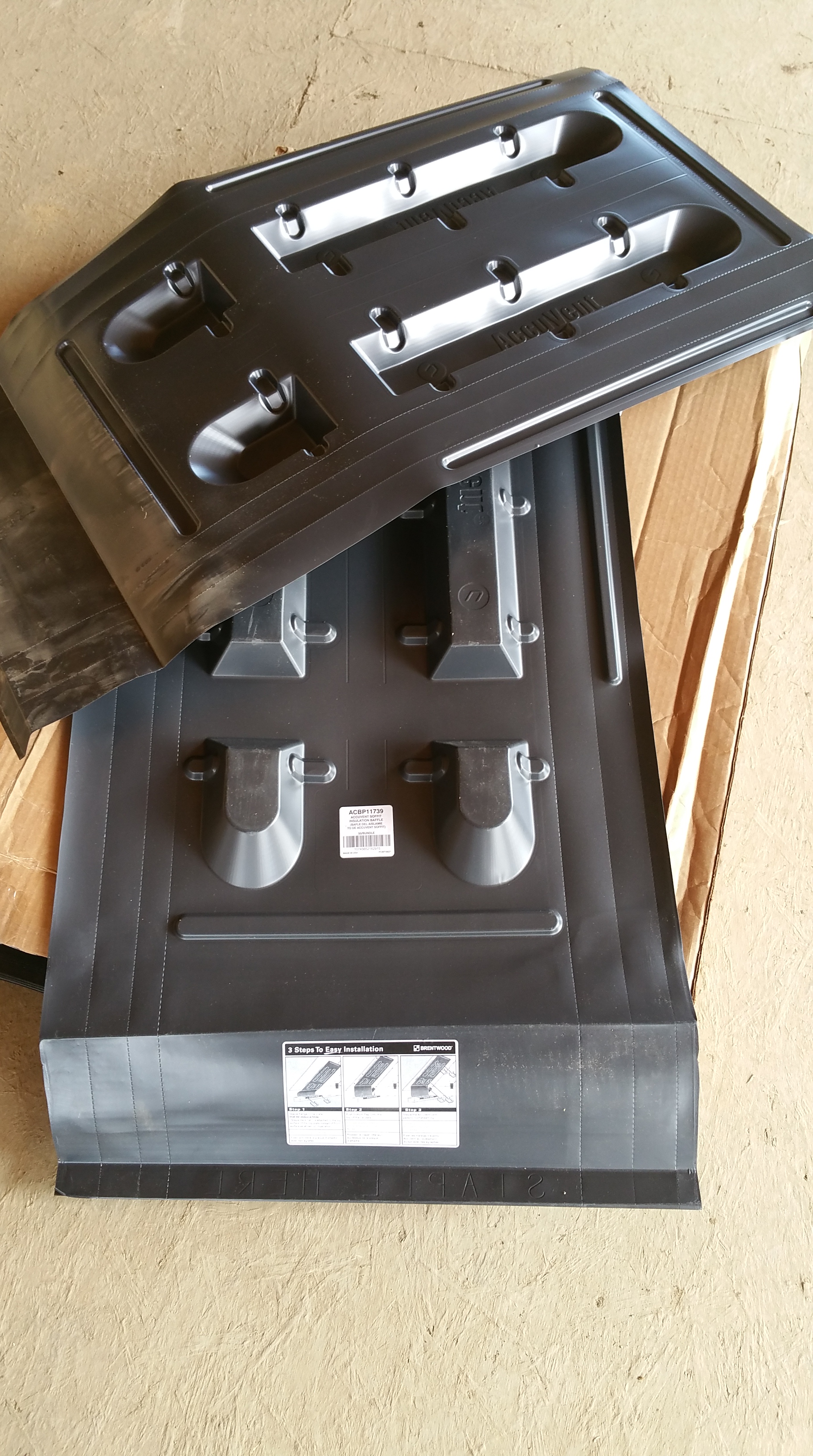
At Home Depot they had Durovent (a foam based insulation baffle) and an AccuVent baffle (black plastic). Both were a disappointment.
I didn’t buy the Durovent — even just seeing it on the shelf and handling it in the store, it looked cheap and unimpressive. It was hard to imagine it holding up under the pressure of any significant amount of blown-in insulation pressing against it.
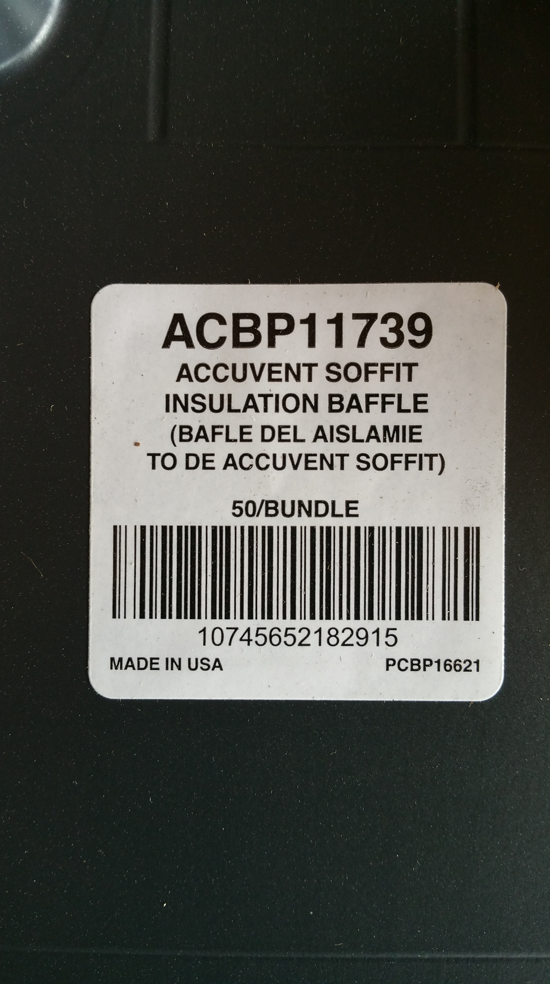
The AccuVent product Home Depot carried only worked in a straight line (no curve to wrap over the back of the Zip sheathing at the top of the wall assembly), ideal for a cathedral ceiling application. After looking around online, I found this other AccuVent product:
Seeing the video made me think it would be an easy installation, but once I had the product on the job site and tried to install one, the realization hit that they would be a pain to properly air seal, and again, I had concerns about blown-in insulation pressing up against it for years.
AccuVent on the job site. It’s hard not to look at these foam/plastic baffles, regardless of brand, and not think: “flimsy”.
Here’s the specific product info:
And here are the installation instructions:
When I realized the AccuVent wasn’t right for our project, it was a moment of, “Uh-oh, now what the hell do I do?”
I assumed there must be a sturdier plastic baffle, but I never found one. Instead, I came across this article:
It was nice to have a solution, but I also knew it would be time consuming and back breaking (also neck straining) — the only thing worse than working with sheet goods is working with sheet goods above your head on a ladder. Nevertheless, I would sleep better knowing it was panels of OSB rubbing up against 2 feet of blown-in cellulose insulation rather than sheets of flimsy plastic. Long term solutions do wonders for peace of mind.
First insulation chute installed.
I used small, cut pieces of 2×4 (six per OSB sheet) as a screwing base (visible in the photo below) to install each insulation chute — screwing the blocks first to the roof trusses, then, after putting the OSB into place, screwing through the OSB and into the bottom of each 2×4.
The blocks were first screwed to the trusses, before each sheet of OSB was attached to the 2×4 blocks from below.
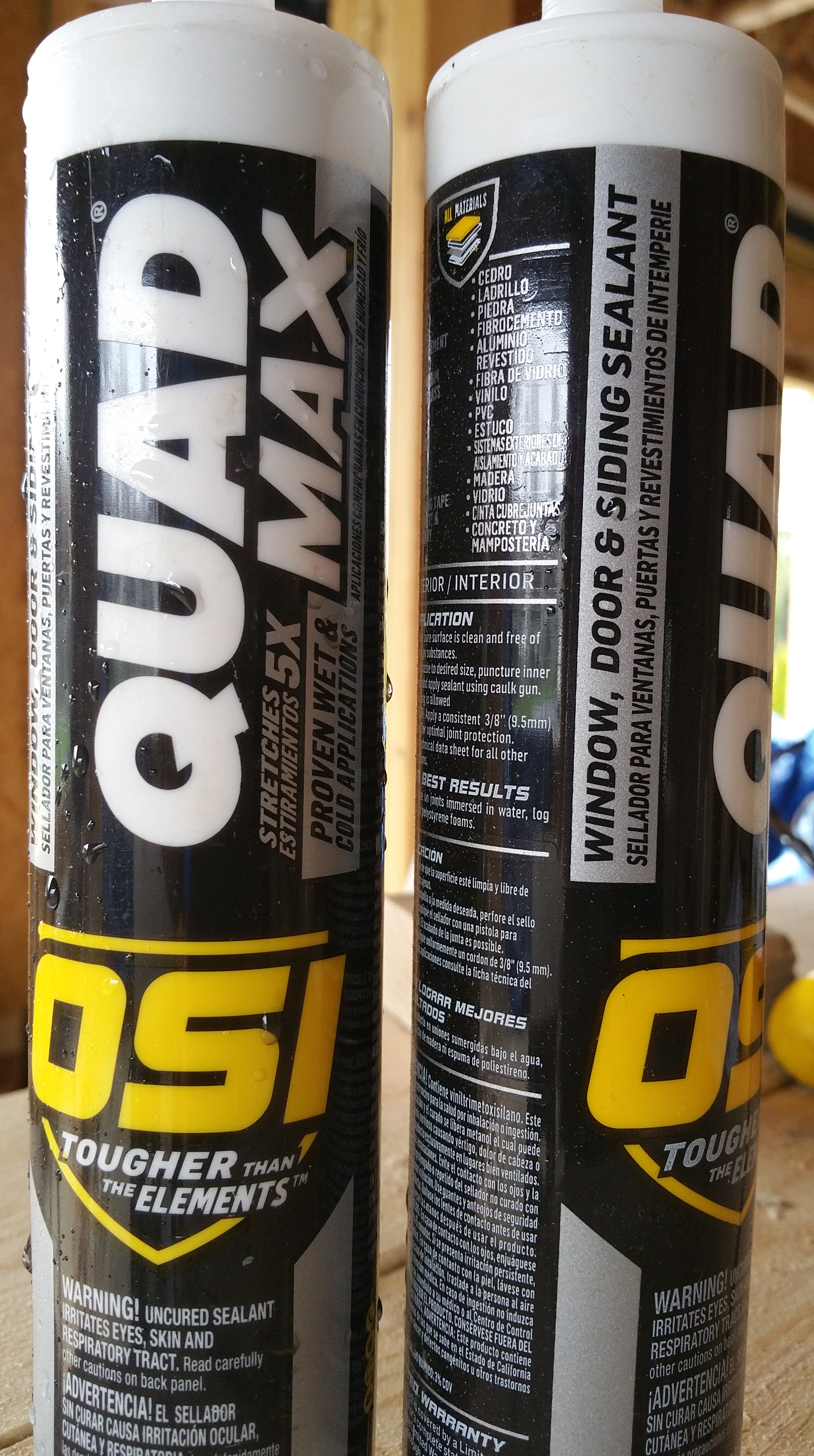
Then, after installing each sheet of OSB, I went around the perimeter sealing all the gaps. Here’s the product I used for that:
The OSI sealant I used to cover the gaps.
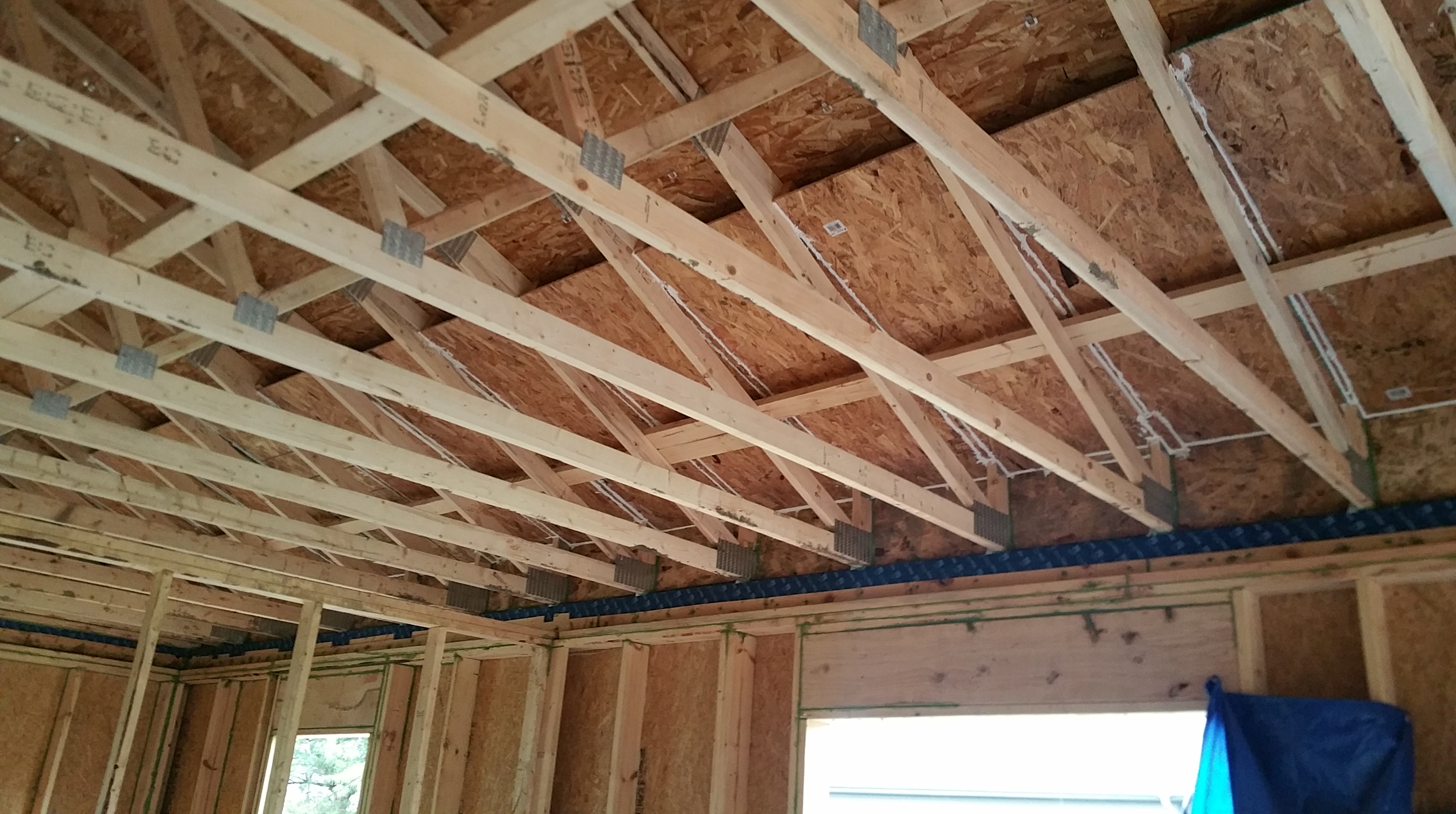
Here’s what the chutes looked like once they were installed on the south side of the house:
And this is what the chutes looked like when completed at the top of the Zip sheathing:
There weren’t always sizable gaps where the OSB chute met the top of the Zip, but when there were, this was pretty typical:
Same area after adding a thin piece of OSB to help cover the gap, and then sealing the area with the OSI sealant:
Looking down a chute before sealing with the OSI:
Gaps visible at the edges before sealing them up with the OSI.
Same view after sealing up the gaps:
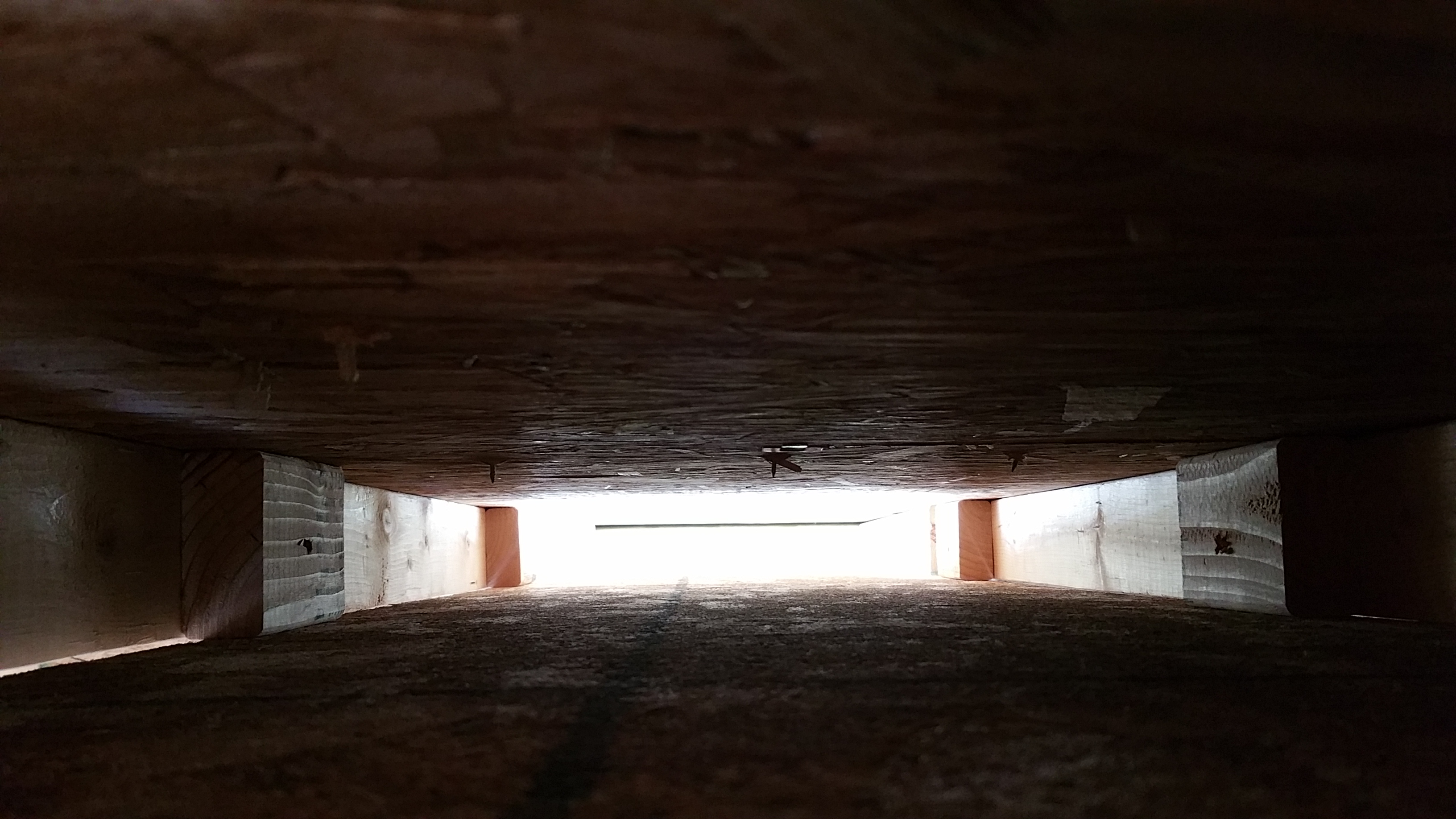
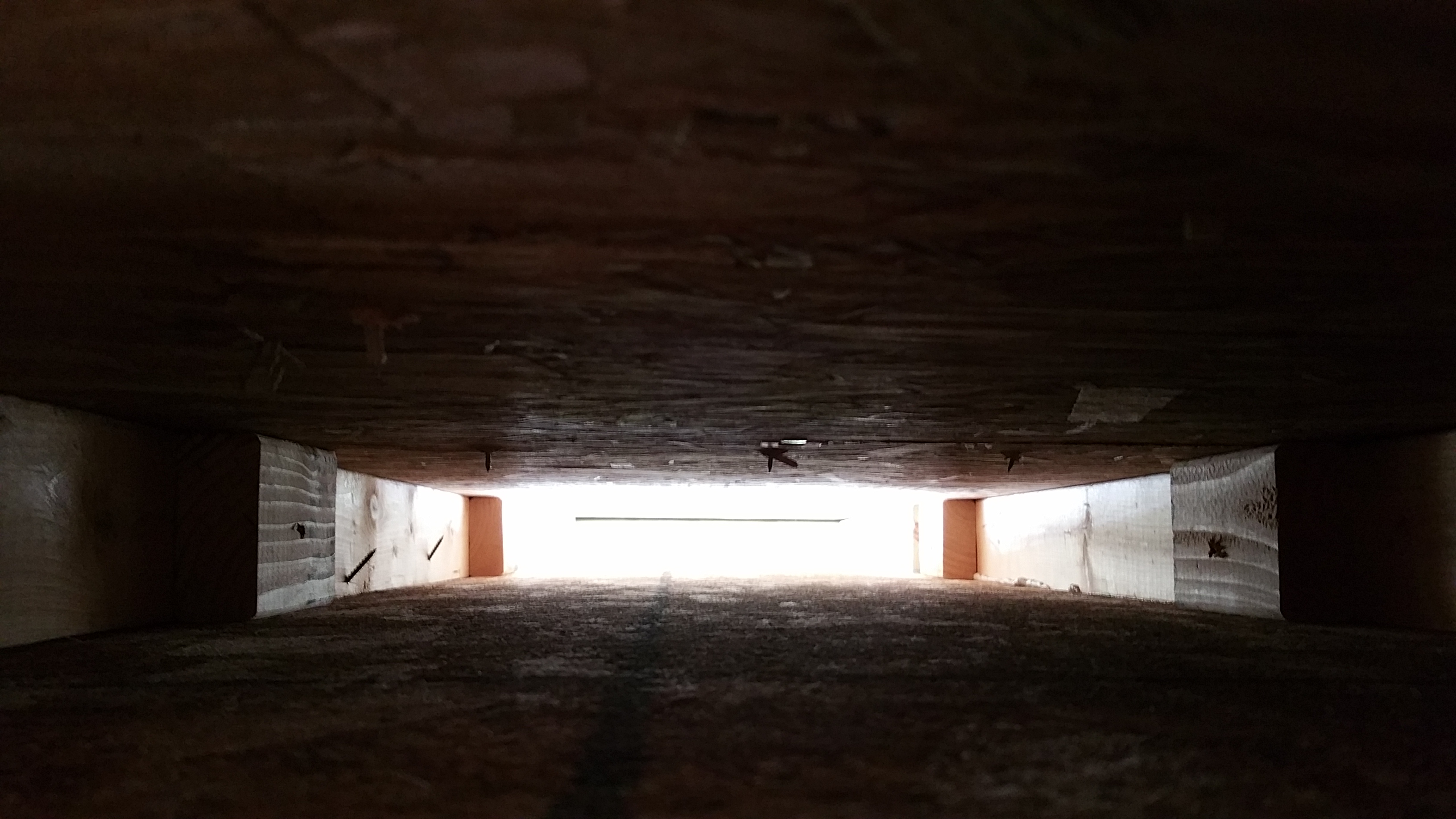
I showed up on a rainy morning to continue installing the chutes, and this picture shows the dramatic before and after view of without chutes and with chutes installed and sealed:
On the left: no chutes and light visible through the soffit. On the right: chutes installed and completely sealed.
Here’s a long view of the chutes:
49 installed with one to go (far left corner).
Final chute installed and sealed.
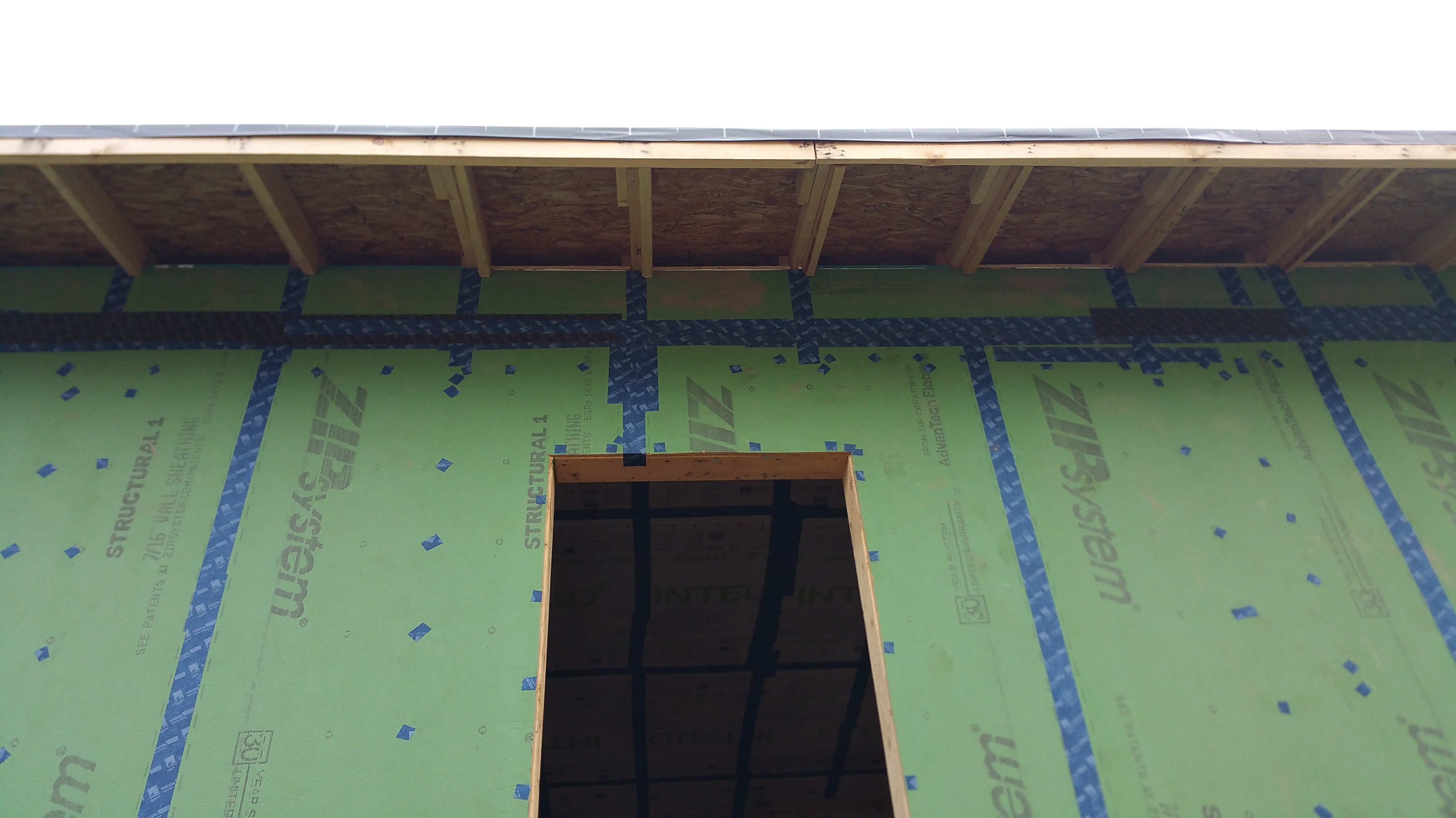
View from outside showing the ends of some of the OSB chutes peeking over the edge of the soffit.
Closer view of the top of the Zip sheathing meeting the OSB chute.
In the attic with the insulation chutes in the background, after the Intello was installed on the ceiling below.
Once the chutes were installed, I was finally ready to put the Intello on the ceiling, which thankfully I didn’t have to install by myself.
[December, 2020 Update: If you’re trying to avoid the time and materials associated with installing site-built plywood chutes, a newer (at least to me) product like Smart Baffles is probably worth considering:
Although, as with any new product, it’s worth the time and effort to do a mock up, in this case with a roof assembly (much like the one shown in their video), along with a partial wall assembly, in order to see how the product works (evaluate the durability of the product, ease of installation, final fit, etc.), especially where (and how) the baffle will meet up with the top of the outside walls.With a mock up, you can avoid (or work through) any issues with the product before you’re on the job site actually installing them (when time and money really matters).]
Once the wall assembly details were figured out, and our ceiling set-up detailed, the transition between the two became the next challenge. In other words, how to carry the air barrier over the top of our exterior walls.
Using a waterproof peel-and-stick membrane to wrap over the top of the wall (going from exterior sheathing — in our case 7/16″ Zip sheathing — to interior side of the top plates) seemed like the easiest way to maintain a continuous air barrier at the wall-to-roof junction. The membrane would also have a nice air sealing gasket effect after the trusses were set in place.
I also found this excellent Hammer and Hand video on YouTube (one of their many helpful videos):
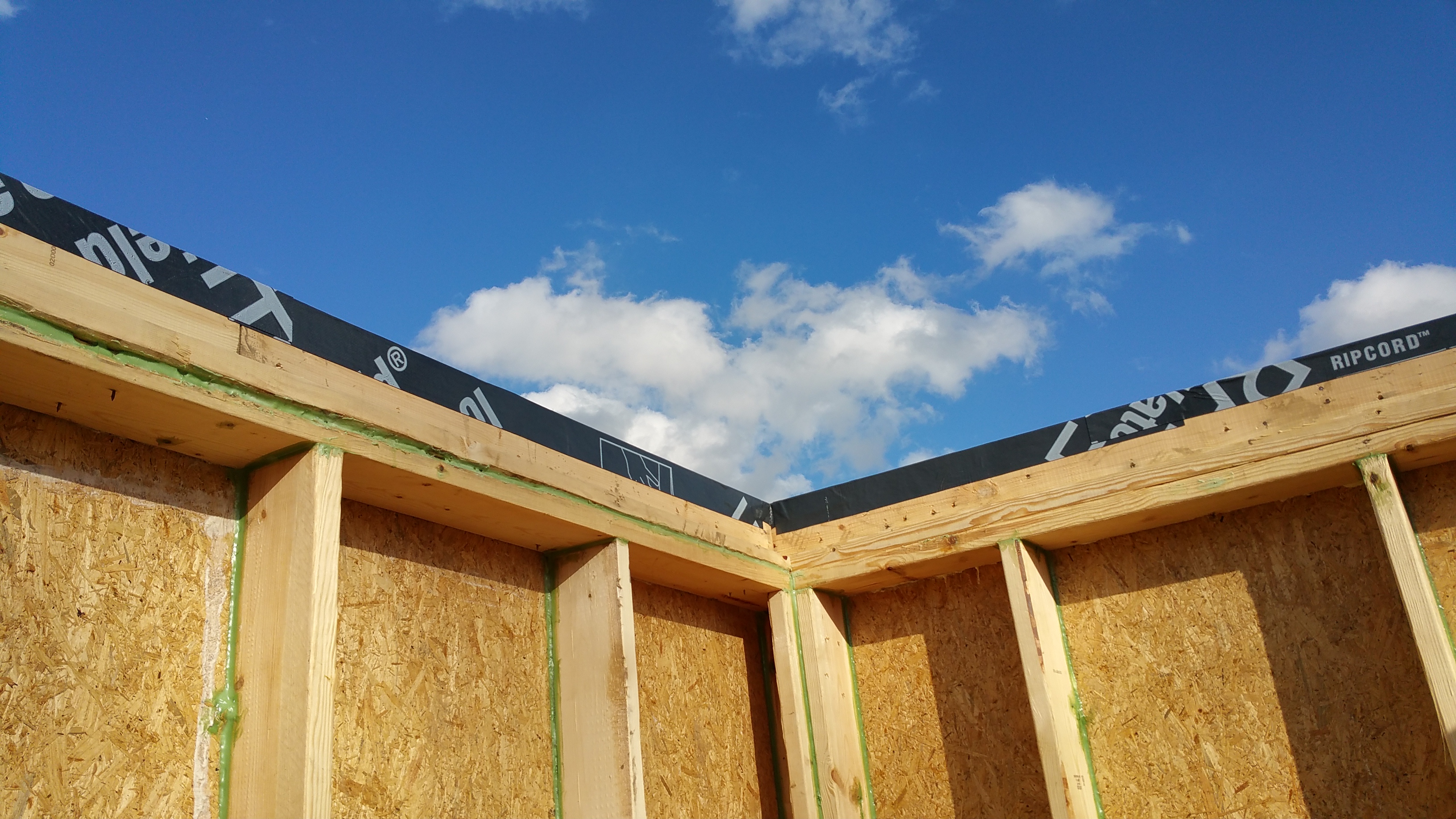
Also, by being able to carry the Zip sheathing up above the top plate of the wall, hugging the bottom of the trusses, meant our 4″ of Roxul Comfortboard 80 over the Zip sheathing would rise above the top of our walls, so that thermally we would be protected going from the exterior walls to the attic, which will be filled with 24″ of blown-in cellulose — making our thermal envelope continuous for the whole house: under the basement slab – exterior of foundation – exterior walls – attic (except for one small gap at the footing-slab-foundation wall connection, which I talk about in a separate post: Foundation Details).
A high R-value wall meets up with a high R-value attic, with no thermal bridging, making our thermal layers continuous. When this is combined with an equally air-tight structure, conditioned air cannot easily escape — resulting in a significantly lower energy demand for heating and cooling (and therefore lower utility bills), and added comfort for the occupants.
Here’s a nice illustration from Fine Homebuildingmagazine showing a similar set-up:
Illustration from Fine Homebuilding magazine.
I tried using rolls of conventional peel-and-stick window flashing membrane, purchased from Home Depot and Mendards, but they performed poorly, even in unseasonably warm temperatures for February in Chicago.
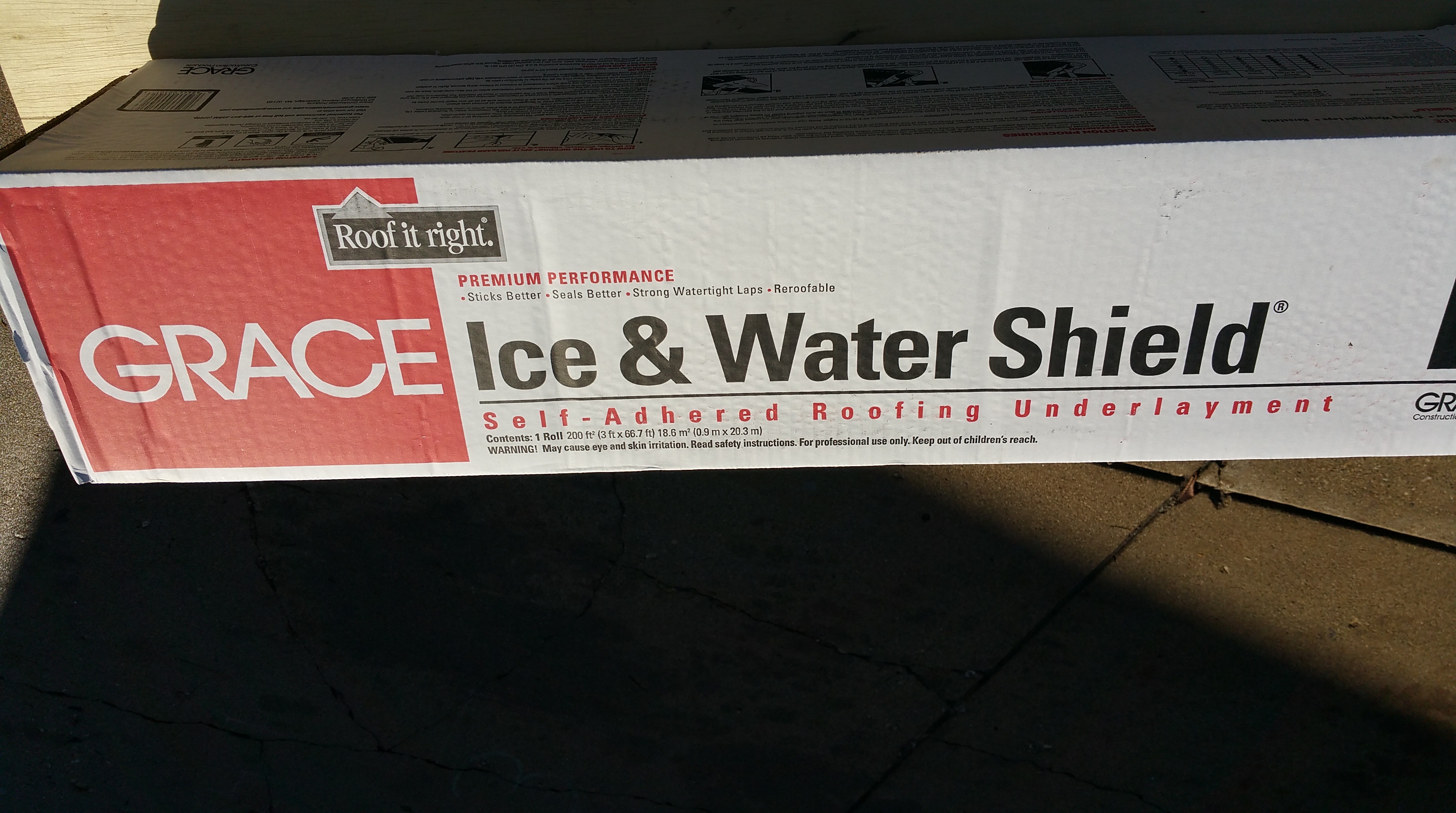
I then switched to Grace Ice and Water Shield, normally used as a roofing underlayment along the first 3-6′ of roof edge.
Purchased this box at Home Depot.
Since it came on a long roll about 4′ wide, my wife and I cut it down to a series of strips that could more easily be applied to the wall-top plate connection.
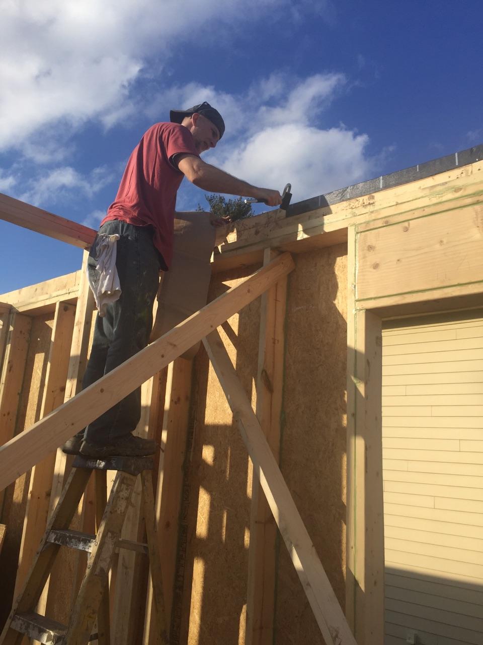
While the sun was out, the Grace membrane worked fairly well, especially when pressure was applied with a J-Roller.
Grace Ice and Water Shield applied to the top of our wall — covering the Zip sheathing/top plate connection.
Unfortunately, the sun and warmer temperatures didn’t stick around long enough for me to finish.
Using a J-Roller to get the Grace Ice and Water Shield to stick better.
This Simpsons sky didn’t last long. In a matter of hours it was back to rainy, gray, and cold — typical Chicago winter weather for February.
When the weather went gray and cold again, we started to use a heat gun to warm up the Grace membrane, which had turned stiff and nearly useless in the cold.
Wagner heat gun for warming up the Grace membrane.
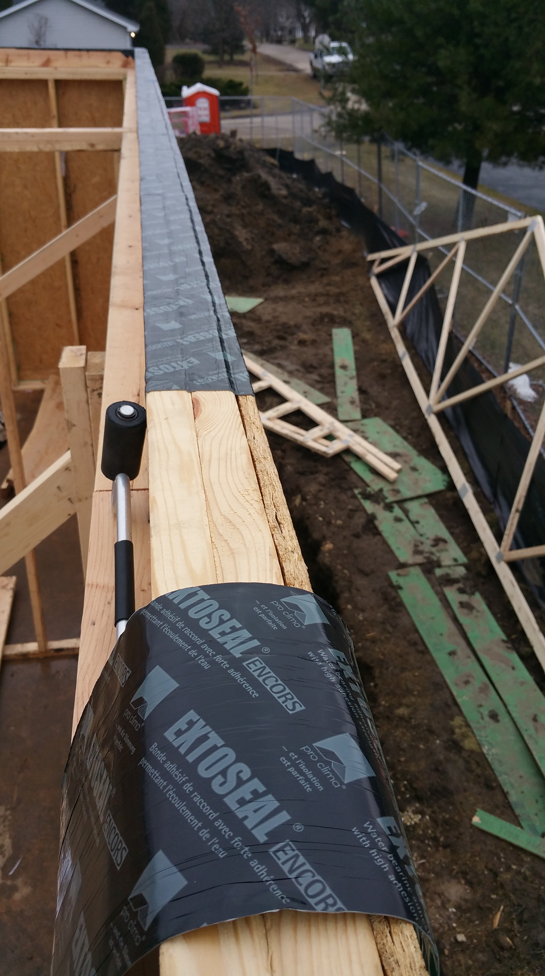
After wasting a lot of time and effort trying to pre-heat the Grace membrane before installing it, I finally relented and switched to the much more expensive (but also much more effective) Extoseal Encors tape from Pro Clima. Where the Grace membrane lost virtually all of its stickiness, the Extoseal Encors stuck easily and consistently, with the J-Roller just helping it to lay flatter and more securely.
Pro Clima’s Extoseal Encors available from475 HPBS.
It was a case of trying to be penny wise but ending up pound foolish. Looking back, I would gladly pay an extra $300 in materials to have those hours of frustration back (including the time it took to run to the store and buy the heat gun, which turned out to be ineffective anyway).
Finishing up the top of the wall.
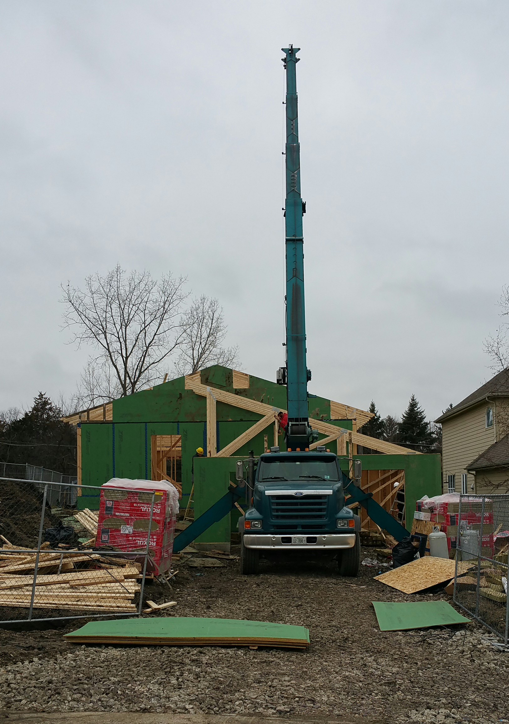
After finishing sealing the Zip sheathing-top plate connection on all the outside perimeter walls over the weekend, it was time for the trusses to be installed.
Trusses
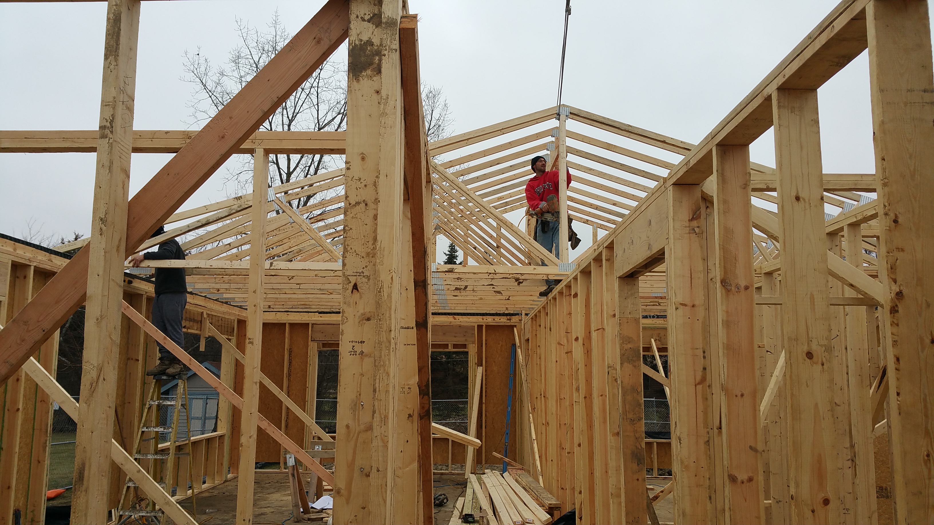
Zach asked me to stand by the front door rough opening and give the crane operator hand signals. It was a fun way to watch the roof take shape.
First truss swinging into place.
Sammy, Zach, and Billy (out of view to the right), landing and setting the trusses.
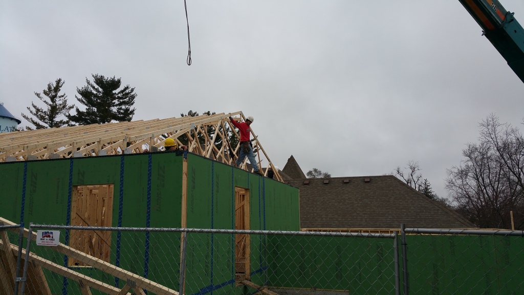
Once the trusses neared the front door, Zach could signal the crane operator himself, so I was able to get some shots from just outside the construction fence.
Sammy, Zach, and Billy landing trusses on the garage.
Setting the trusses on the garage. The basic silhouette of the house starts to come to life.
Once the trusses were on, and the guys had a chance to install the final top row of Zip sheathing (up to the bottom of the trusses on the exterior side of the wall), I could move inside to seal all the connections from the interior.
Top of Wall (Interior)
Because of the cold, the Grace membrane was beginning to lift at the edges in certain spots, so just to make sure it had a nice long-term seal, I went around the perimeter of the house and used a layer of Tescon Vana (3″ wide) tape to seal the edge of the Grace membrane.
Trusses sitting on Grace and Extoseal Encors (other sections of top plate), with the final, top row of Zip sheathing sealed to the trusses with HF Sealant.
The picture below shows all the connections involved: top of Zip sheathing meeting the roof trusses and the top plate of the outside wall:
HF Sealant helps to air seal the Zip-truss and Zip-Grace/Extoseal Encors connections.
Looking up at the top row of Zip sheathing attached to the outside edge of the raised heel trusses.
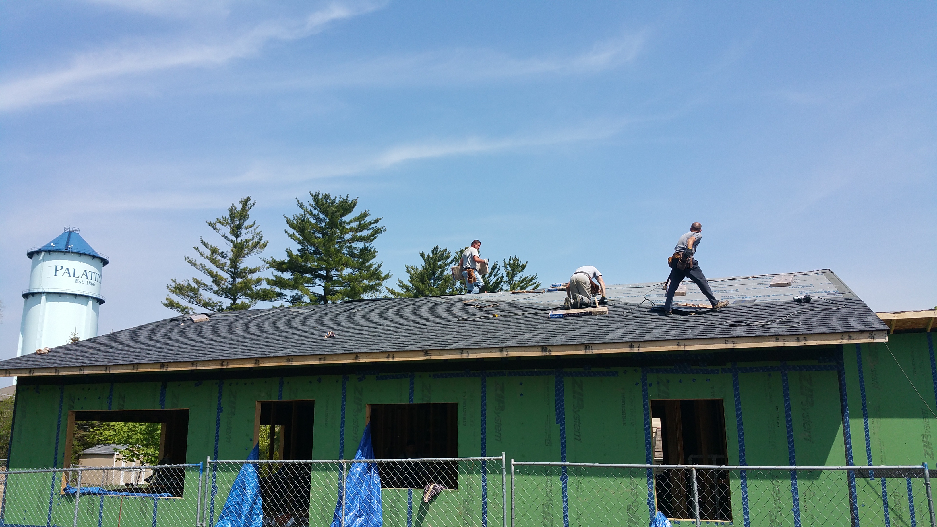
Shingles
We had to wait for shingles for quite some time. First we had to fire our GC’s, and then I had to find a roofer and a plumber (to make penetrations through the roof before the shingles went on). But before the plumber could even start, I had to get the Intello installed on the ceiling. And even before that, I had to figure out the insulation baffles, which I’ll talk about in a separate post.
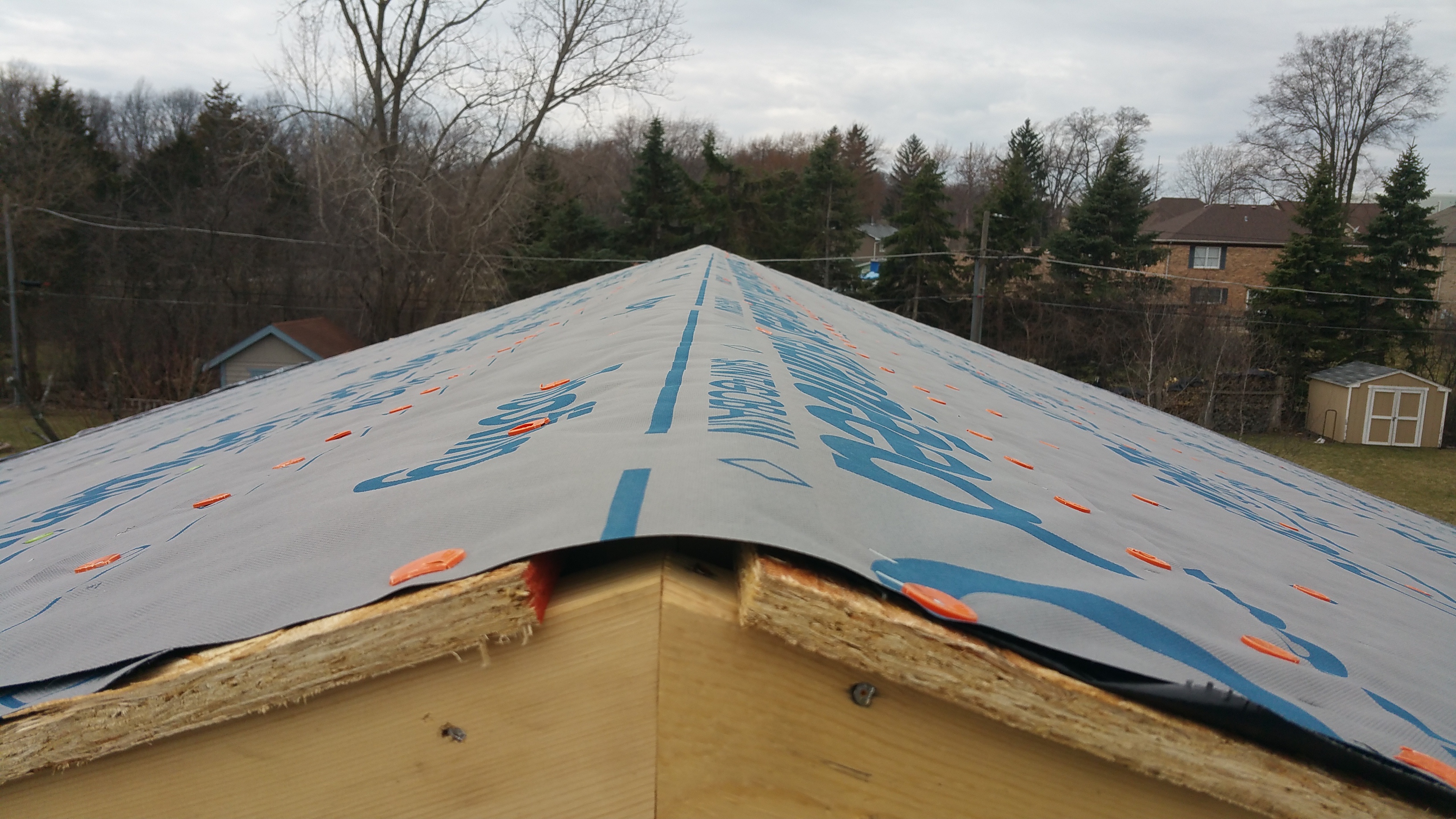
It took awhile to find a roofer since they would have to make three separate trips for a relatively small job. The first trip was just to set down the Grace Ice and Water Shield at the edges of the roof, along with a synthetic roof underlayment (the consensus was that typical roofing felt wouldn’t hold up to long term exposure). As it turned out, it took weeks before the plumbers made their penetrations through the roof sheathing (literally the day the roofers showed up — a long, horrible story in and of itself that I’ll save for later).
Synthetic underlayment covering the ridge line until the shingles and a ridge vent can be installed.
The second trip out was to install the shingles on the roof of the house, while the third trip to install shingles on the garage roof could only happen after the Roxul on the exterior of our Zip sheathing was installed (in order to make a proper sealed connection between the wall of the house and the garage roof).
There weren’t many roofers willing to work with our unique Passive House sequencing, but our roofer was kind enough to take it on.
Grace Ice and Water Shield rolling up on itself after the wind got ahold of it.
Unfortunately, the day after the guys installed the Grace membrane and the synthetic underlayment, we had a cold, blustery day. Once the wind grabbed the Grace membrane, the membrane rolled up on itself, turning it into a real mess.
Because of our recent past bad experiences with general contractors, I just assumed I was on my own, so I spent a couple of hours putting down new layers of the Grace membrane. When Peterson roofing found out, they were shocked I did it myself, and assured me I could’ve called them and they would’ve come back out. We were so used to people not following through, that low expectations meant it didn’t even occur to me to call them.
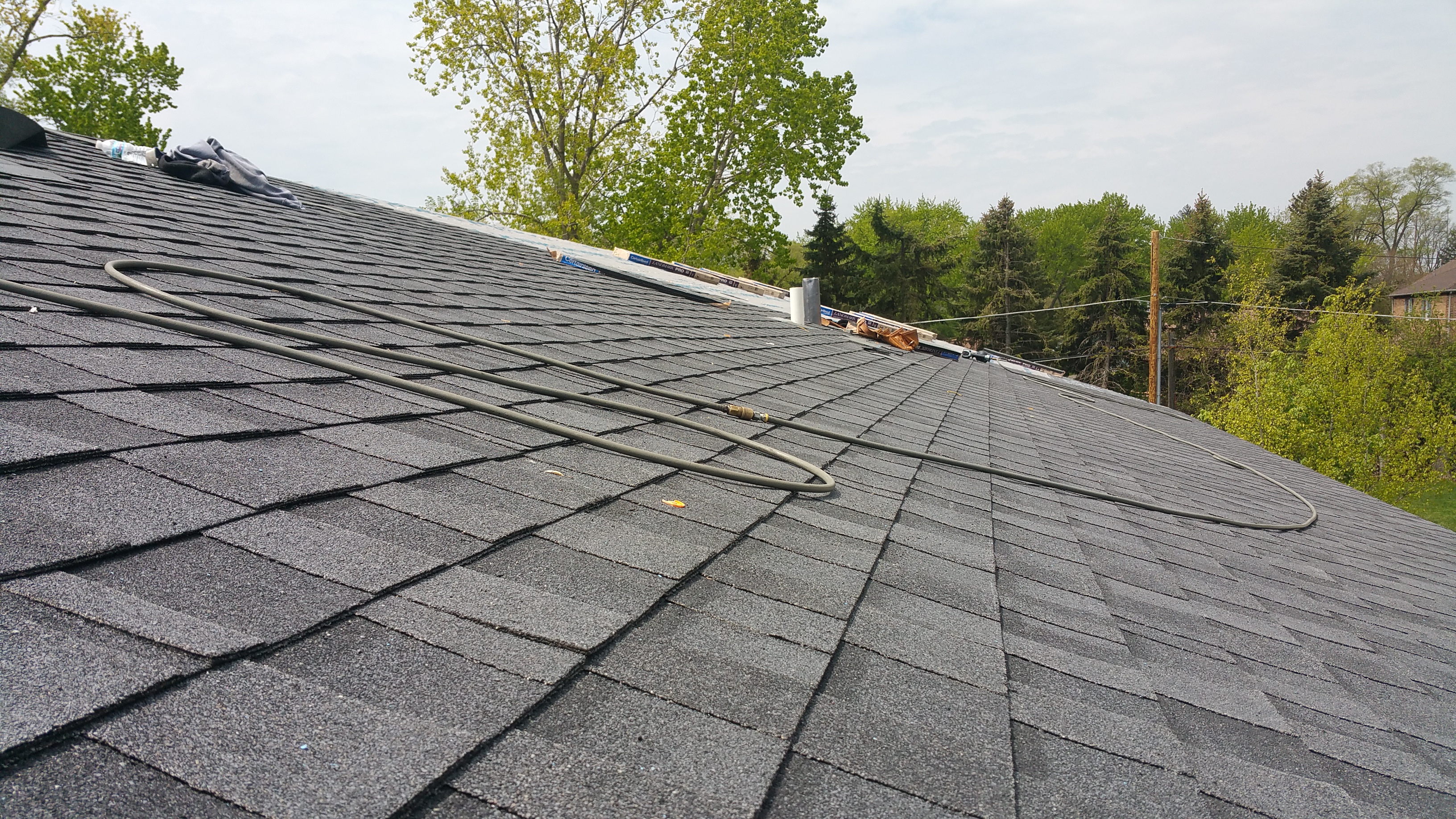
We initially were going to use Certainteed’s Landmark TL shingle, which mimics a cedar shake shingle profile, but Armando from Midwest Roofing Supplyin Schaumburg, Illinois was kind enough to take the time to walk me through the options available, and explained that because our roofline isn’t steep, only the neighbors from their second story windows would get to appreciate the effect. He recommended we save some money, while not giving up on quality or durability, and go with the Landmark Pro product.
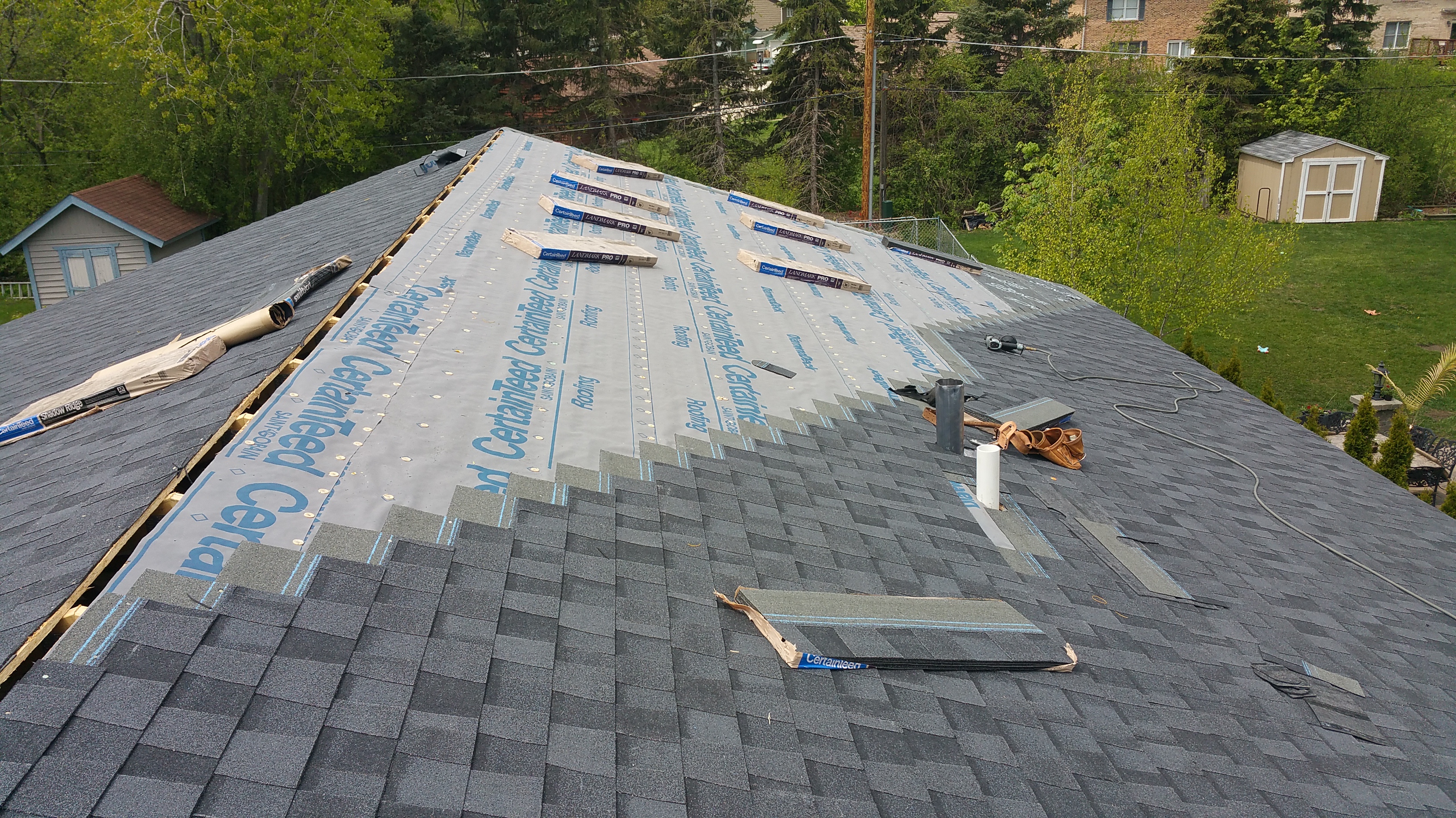
Shingles going down on the roof of the house.
The shingles went on quickly since we have a relatively small and simple roof. In addition to the aesthetic leap the shingles made on the appearance of the structure, it also meant I didn’t have to go around cleaning up the subfloor every time it rained.
Although the synthetic underlayment worked pretty well at keeping the rain out, if there was significant wind combined with rain, the water easily found its way under the underlayment where it could then drip and fall on the subflooring below — pretty depressing showing up to the job site after a hard rain knowing I was going to spend the first hour just cleaning up and looking for leaks.
Seeing this felt like a tremendous amount of progress was being made. It also meant an end to our roof leaks on the interior.
Shingles going on quickly. Only two penetrations through the roof — main waste stack and radon.
After they cut the opening for the ridge vent, but before it was installed, I managed to get this shot from inside:
When choosing what to put in our walls, we knew we wanted to try and balance high R-values (well above the current building code) with a limited environmental impact.
we decided to use many of the following elements employed by Hammer & Hand:
Hammer & Hand wall assembly for their ‘Madrona House’.
In terms of materials, there are any number of options for putting a wall assembly together. For instance, we really wanted to use the sheep wool, but cost and worries (unfounded or not) about availability, led us eventually to Roxul (the Hammer & Hand videos below proved especially helpful in this regard).
After seeing the wall assemblies Hammer & Hand has been using, and how they’ve evolved over time, we felt the Madrona House set-up represented a good balance between cost-environmental impact-availability-ease of installation. We will also be following their lead by using the Prosoco R-Guard series of products to help with air-sealing our building envelope.
Nevertheless, we did make a couple of changes to the Madrona House set-up. For example, we’re using 4″ of Roxul Comfortboard 80 on the exterior side of the Zip sheathing (based on our colder climate zone), and we will be using Roxul R23 batts in the stud bays, along with the Intello vapor retarder, stapled and taped to cover the stud bays. Otherwise, we will be sticking pretty close to the Hammer & Hand Madrona House wall assembly.
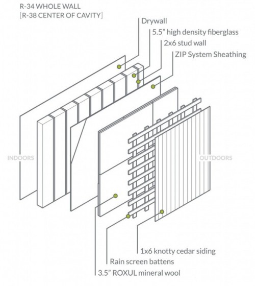
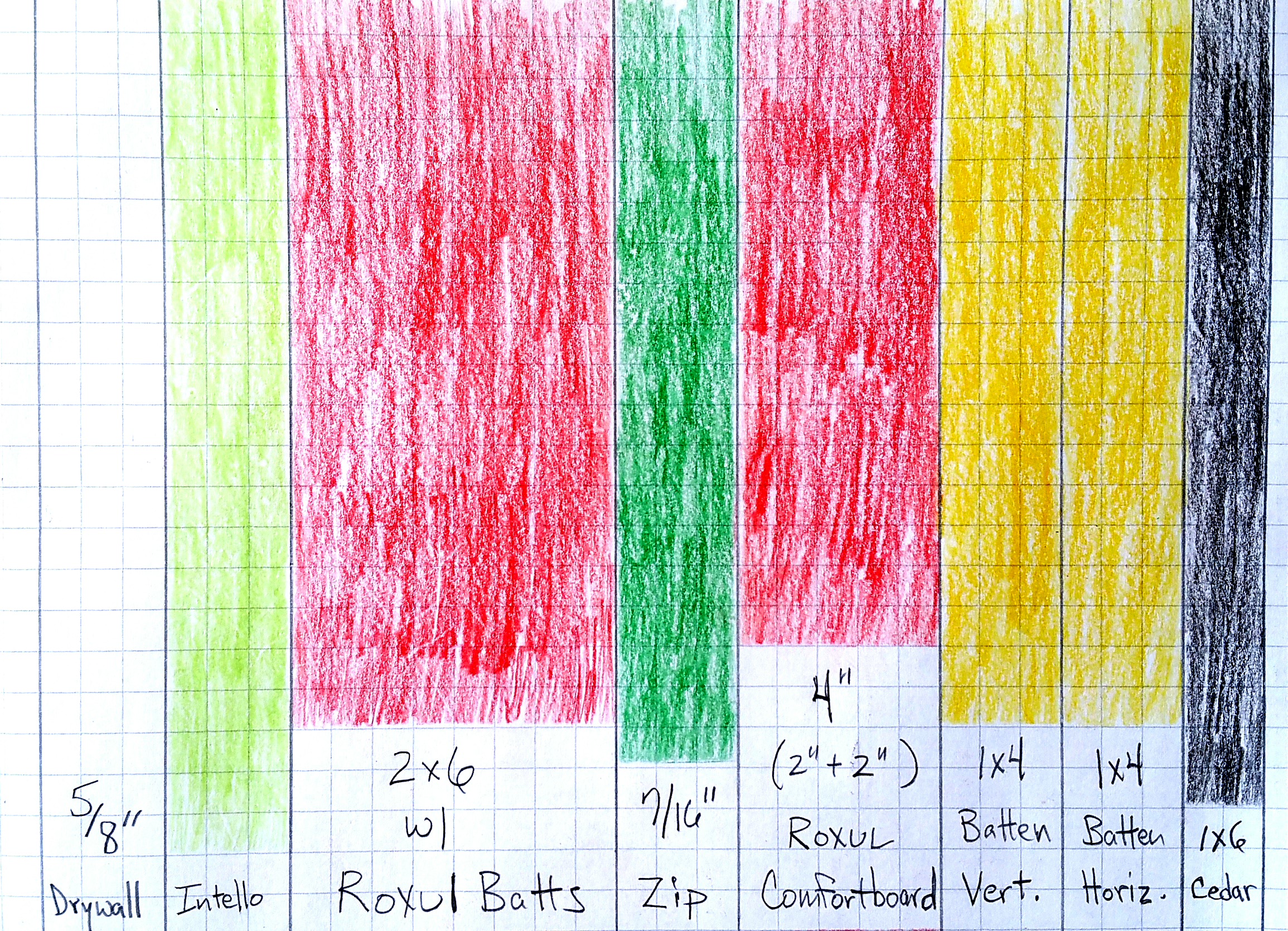
So from drywall to exterior siding (interior – exterior), this will be our wall assembly:
Roxul R23 Batts in 2×6 stud bays (24″ o.c.) (roxul.com)
Zip board (for structural sheathing and WRB; seams covered w/ Joint and Seam Filler)
4″ of Roxul Comfortboard 80 (two layers: 2″ + 2″)
2-Layers of 1×4 furring strips (aka battens or strapping) as a nailing base for the cedar siding
1×6 T&G Cedar (charred and oiled with a few boards left natural as an accent — most of it oriented vertically, hence the need for a second layer of furring strips).
A crude rendering of our wall assembly using my daughter’s coloredpencils.
A collection of helpful videos explaining the various elements we’re going to use, and why they’re effective:
Without the information available from sources like Building Science Corporation (they have a lot of interesting research documents) and design-builders like Hammer & Hand(not to mention Green Building Advisor and similar sites and forums that allow consumers to Q&A with expert builders and designers in “green” architecture), trying to build structures to such exacting standards (e.g. Passive House – Pretty Good House – Net Zero) would be exceedingly difficult, if not impossible, for those without previous, direct experience in this type of building program. I can’t express how thankful I am that so many individuals and businesses like these are willing to share their years of experience and knowledge with newbies like myself.
Here are the Hammer & Hand videos that initially sparked my interest in using Roxul rather than foam:
Instead of using tape for exterior seams, we are going to use the R-Guard series of products from Prosoco:
For various interior seams and connections we anticipate using the Tescon Vana tape, or an appropriate gunned sealant.
In the summer my wife and I teach a class together, called Excel 2, which is one small component of a larger, overall Excel Program (my wife is a high school Social Studies teacher).
Typically, Excel students come from first-generation immigrant families. They are college-bound students who have exhibited great potential, but who are in need of some encouragement, particularly in regards to taking Advanced Placement (AP) courses (huffington post). For most of our students, they will be the first ones in their family to attend college, so it is understandably an intimidating prospect in any number of ways.
The course itself is three weeks in the summer session, its focus on developing reading and writing skills by utilizing non-fiction reading assignments. We emphasize the importance of correct spelling, proper grammar usage, and attention to detail by requiring multiple revisions to several thesis paragraphs, which are themselves based mostly on college-level reading assignments.
You can imagine how well this goes over with incoming high school sophomores and juniors — especially in summer. We’ve tried to overcome this dilemma (how to motivate young high school students to tackle a course based on rigor when many of their friends are out enjoying summer break) by delving into topics they are intimately familiar with, but hopefully in ways they have not yet confronted.
Some of our Excel students with my wife, Anita: (front row) Aubrey and Imani, (back row) Eduardo, Anita, Cecelia, and Karen.
As a whole, 50% of the students attending Palatine High School qualify for free and reduced lunch. Not surprisingly, then, the Excel students face some unique, if not daunting challenges, both in and out of the classroom. In addition to the normal stresses associated with being a teenager, many of them deal with balancing school work with long work hours at low-paying jobs (helping their families make ends meet), social pressures to stray down the wrong path (in any number of ways), and even (most heart-breaking of all) confronting what researchers term being food insecure — in plain English, not always knowing when or where they will get their next meal.
We present the class to the students as an opportunity to test themselves, to really see where they are, currently, in terms of a whole host of skills. The main goal of the Excel 2 program, therefore, is to really challenge their abilities, not just in terms of reading and writing skills, but also soft skills such as interpersonal communication, the importance of body language, time management, and self-discipline.
Essentially, we try to give them a college-level course experience, hoping it better prepares them for the eventual reality. In other words, we’d rather they struggle in high school with us than have it happen when away from home for the first time, off on their own, at college (atlantic)(newsweek)(washington post).
Here’s an example of our ever-changing syllabus: Excel 2 – 2015
As you can see from the reading assignments, we encourage our students to start asking questions about everyday things they may be taking for granted. We hope this sharpens critical thinking skills, but we also hope it encourages them to be more active participants in their lives, rather than just sleepwalking through their days as passive consumers.
Consequently, when it came time for us to find a new place to live, we saw it as a good opportunity to practice what we preach:
What exactly do you want from a new house?
If you’re going to buy a house (and you’re lucky enough to even contemplate doing so), what should it look like? A condo? A townhouse? Or a single-family residence?
In which neighborhood are you going to buy?
How many square feet do you want (or need)? How many bedrooms? Do you want (or need) a formal living room or dining room? Do you want (or need) a basement?
What architectural style appeals to you?
How are you going to furnish the interior?
Should you care about indoor air quality (IAQ)? And if you do, how do you protect it or improve it?
What do you want in your walls and attic for insulation? How much do you need?
How much will utilities cost? Are there cost-effective ways to reduce those costs?
Are renewables — solar, wind, or geothermal — worth considering? How long is the payback period?
Do you want your house to be environmentally friendly — and what does that mean anyway?
Instead of moving into the typical, leaky, not very environmentally friendly suburban condo, townhome, or house (we were leaving behind the latter), we thought it would be more interesting to see just how “green” we could make our next house.
Because we wanted a yard to do plenty of landscaping and gardening, we narrowed the choices down to a single-family house. And, instead of tackling the challenges that come with a retrofit, we decided to try building new.
Much like hearing Jonathan Ive talk about an Apple keyboard, we appreciated the detail required to meet the certified Passive House standard. At the time (summer 2014), this seemed like the way to go.
After the experience we had with our original builder(2015), and then subsequently trying to learn as much as possible about the Passive House standard, in addition to discovering the Pretty Good House concept along the way, our house plans have evolved into a kind of 3-headed hybrid: Passive House science+Pretty Good House+Net Zero (Zero Net Energy: ZNE).
The goal of all three: dramatically reduce the energy consumption of our house as much as possible (especially our dependence on the energy grid). We also want to do a significant amount of planting and growing in our yard, mostly xeric plants that require little additional watering, in order to combine house and yard into an eco-friendly system of sorts.
Our last home (approx. 2800 sq. ft.) was a fairly typical suburban tract house. It had builder-grade windows and doors (most of which had to be replaced after just a few years), very little insulation in the walls (the switch for the back porch light would actually ice up when temperatures fell below 20° F), and it had a great deal of under-utilized space (e.g. a two-story foyer, a formal living room and dining room, and a fourth bedroom, all of which saw little use).
With our new home (just over 1500 sq. ft. of living space), we’re trying to turn all of this on its head so we end up with something we really want and will enjoy. To paraphrase Kevin McCloud: ‘maybe it’s better to have a little bit of something special than a lot of something mediocre’.
An oft-quoted statistic (1)suggests a significant amount of our greenhouse gas emissions can be attributed to our structures (typically the figure is in the 40-50% range) — including residential, commercial, industrial, and governmental — so maybe change really does begin at home (SA)(greenbelt movement).
(1) According to a recent Fine Homebuilding article, “Better Than Average”, by Brian Pontolilo: “It’s not clear how much our homes contribute to greenhouse-gas emissions and to climate change. The most recent data available from the Department of Energy is from 2009-2010. Outdated as it is, this data indicates that residential buildings contribute around 20% of total U.S. greenhouse-gas emissions. This includes fossil fuels used on-site (e.g. natural gas for cooking and heating) as well as electricity.” (September, 2016 issue, p. 64)
The title of this blog entry was lifted from a lyric in this Talking Heads song:


")


You must be logged in to post a comment.