
The Bottom of our Thermal Envelope
Following Passive House principles, we knew we were going to insulate and air seal our basement slab. As explained on the Passipedia website:
“The most important principle for energy efficient construction is a continuous insulating envelope all around the building… which minimises heat losses like a warm coat. In addition to the insulating envelope, there should also be an airtight layer… as most insulation materials are not airtight. Independently of the construction, materials or building technology, one rule is always applicable: both insulation and airtight layers need to be continuous.”
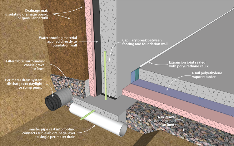
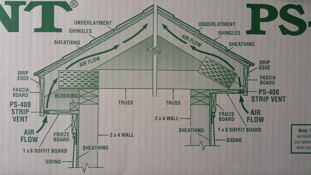
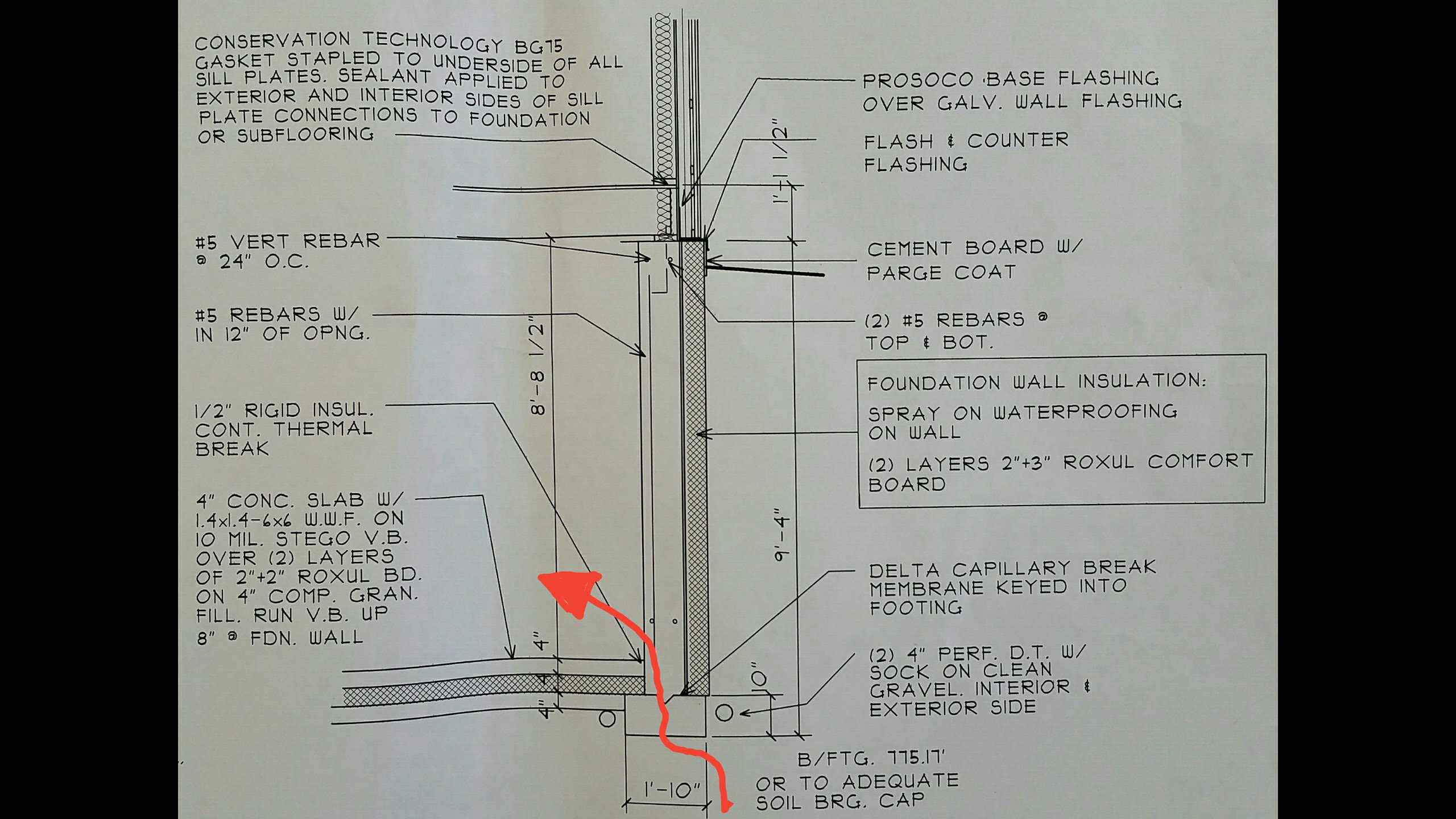
The illustration above also shows the “red pen test”, which is supposed to occur in the design phase of a project, when it’s much easier to address weaknesses or errors in the details of a design — not necessarily just for air sealing, it’s also effective when looking for points of potential water intrusion (e.g., this GBA article), or even to test the thermal layer for areas of thermal bridging. The basic idea is that if your layers aren’t continuous you’ll find yourself lifting your red pen, meaning it’s an area that needs to be addressed.
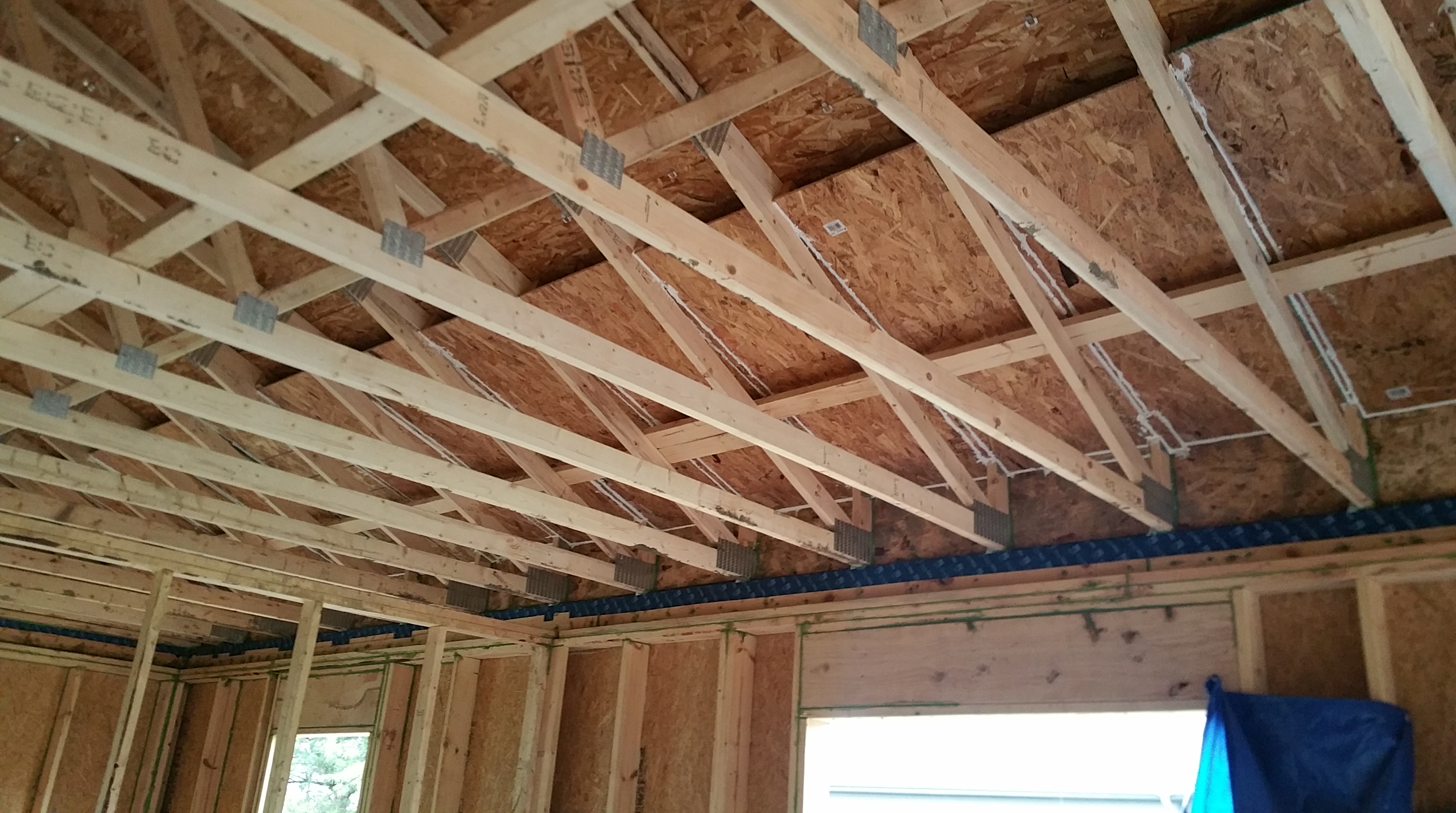
An effective way of thinking about a structure, utilized by high-performance builders, is to think in terms of 6 sides rather than just 4 when contemplating the details for air sealing and insulating: 4 walls, the attic/roof, and the basement (or frost-protected slab).
A similar approach to Passive House for building high-performance structures is adopted by advocates of The Pretty Good House concept, even if it’s less stringent, more open to interpretation, and tends to be more “rule of thumb” rather than energy model driven (e.g. PHPP or WUFI).
Based on our climate region, which is Zone 5, we decided we wanted to shoot for 16/20/40/60 for insulation R-values — the series of numbers represent R-values for under the basement slab/ the exterior foundation walls/ framed exterior walls/ and the attic (our attic R-value proved to be significantly higher than 60, but more on that later) — which is in the ballpark for both PGH and Passive House (here’s an excellent overall summary of the PH concept I recently came across: EcoCor).
Arguably, the “sweet spot” for how much insulation makes sense for these areas, even when adjusted for climate region, is still a topic for heated debate. Nevertheless, it’s important to keep in mind that the more simple the form your structure takes — for example, 2-story cubes without basements —
the easier it is to achieve Passive House, or similar building standards, since it simplifies framing, air sealing, and limits the exterior surface area in ways that a single story ranch that is spread out and has all kinds of nooks and crannies does not (the difference also has serious ramifications for overall heating and cooling demand). Likewise, simple forms also make it easier to figure out how much insulation you need to reach a benchmark like Passive House or PGH. A simple form can also have durability implications.
Our R-values were based on a number of considerations: the construction drawings of our original builder, information made available by Hammer and Hand (in particular their Madrona House project), and articles on the Building Science Corporation (in particular: 1 and 2) and Green Building Advisor websites. These resources, all of which have proven to be indispensable at every stage of the build, have made our project possible.
In terms of the details around the slab and the foundation walls, this article from the DOE also proved to be especially helpful: Foundation Handbook
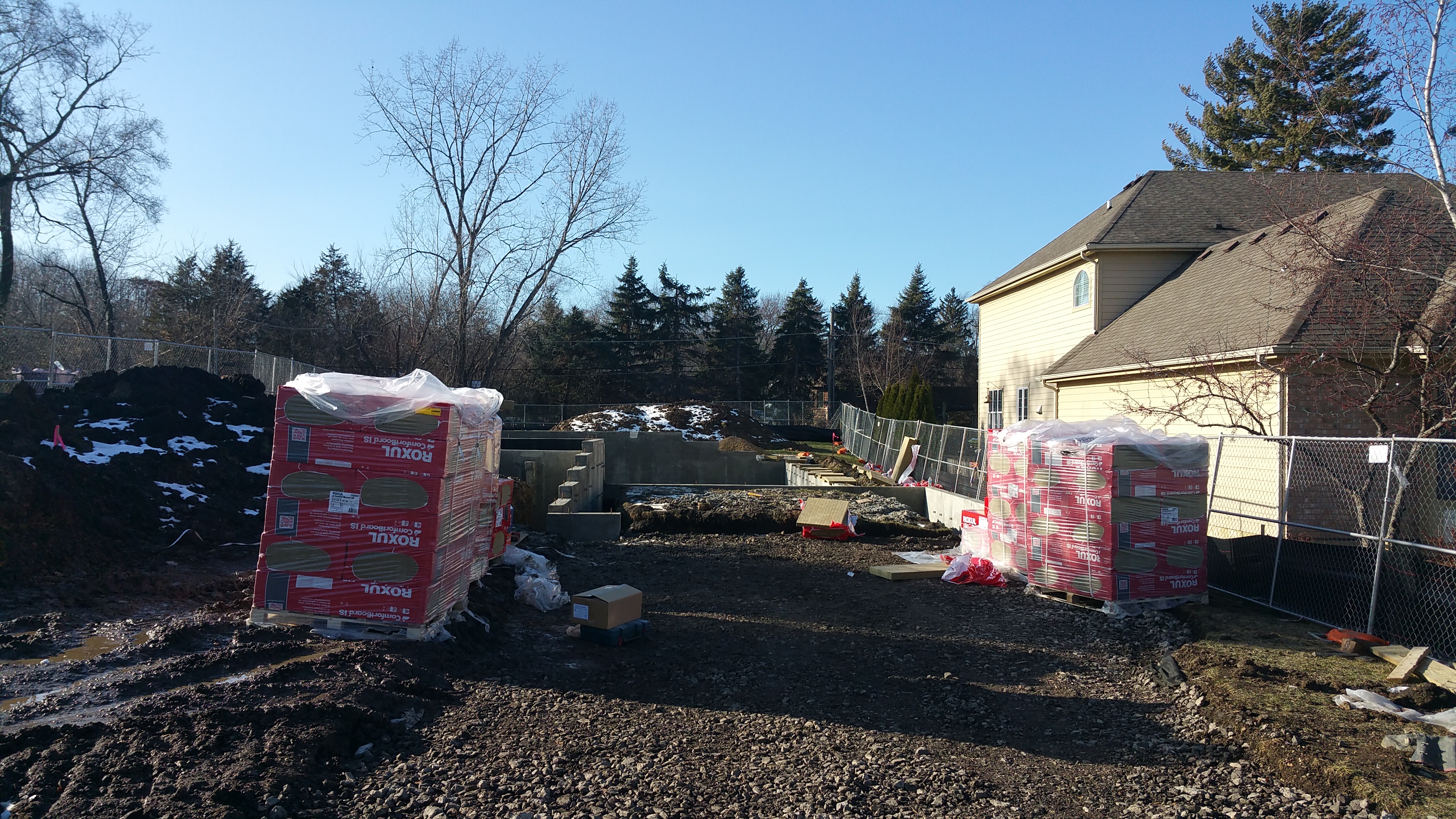
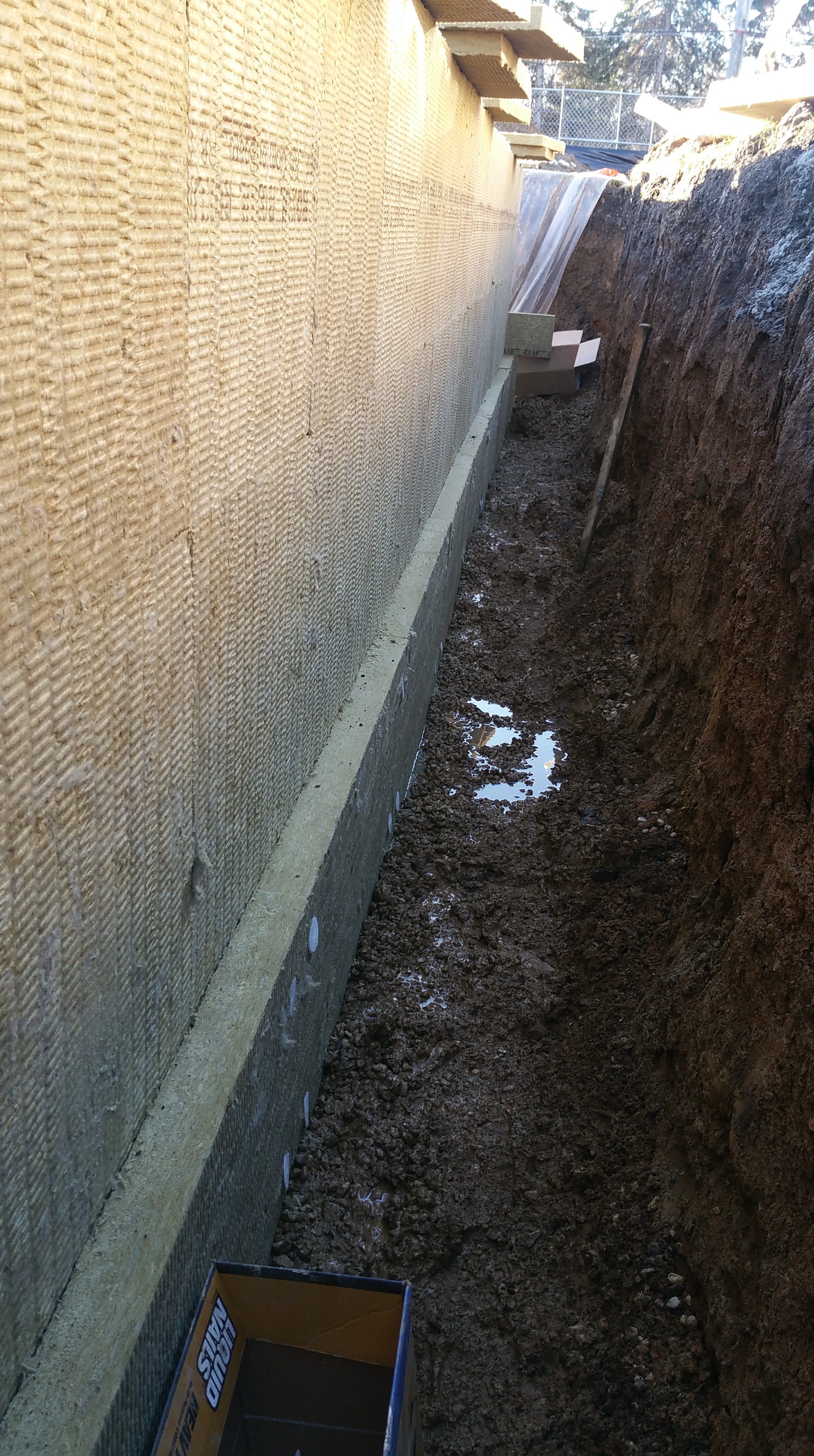
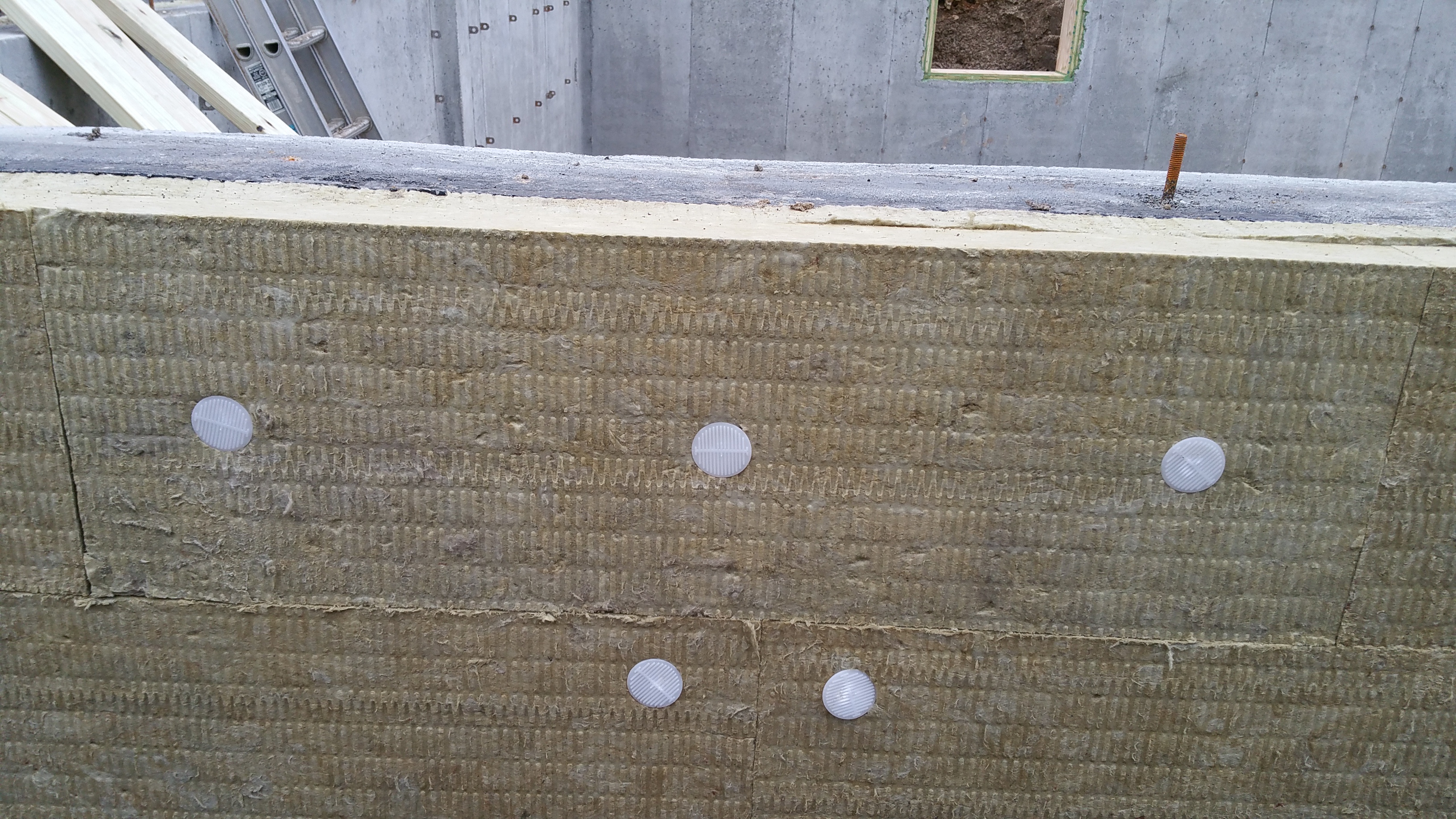
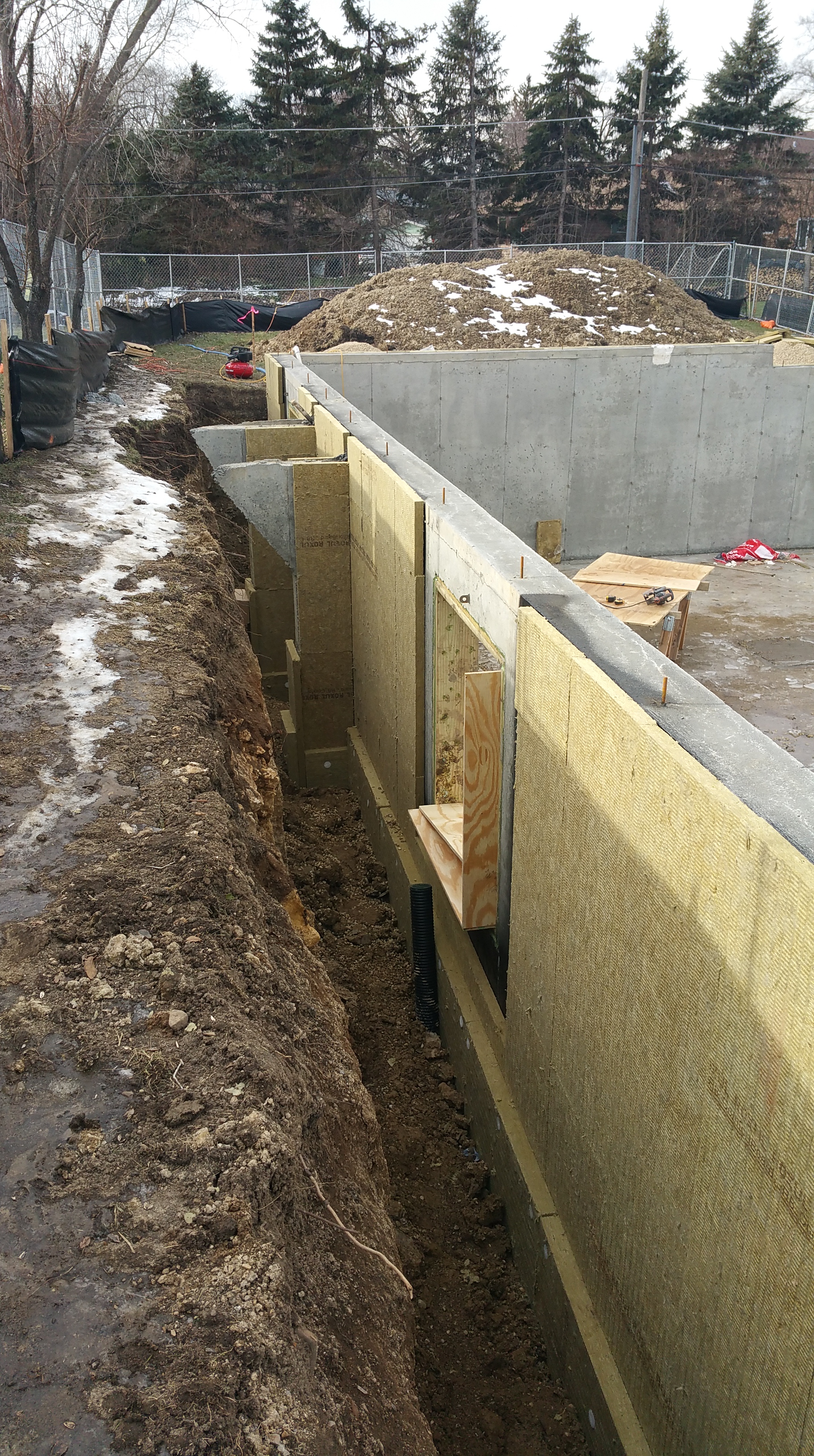
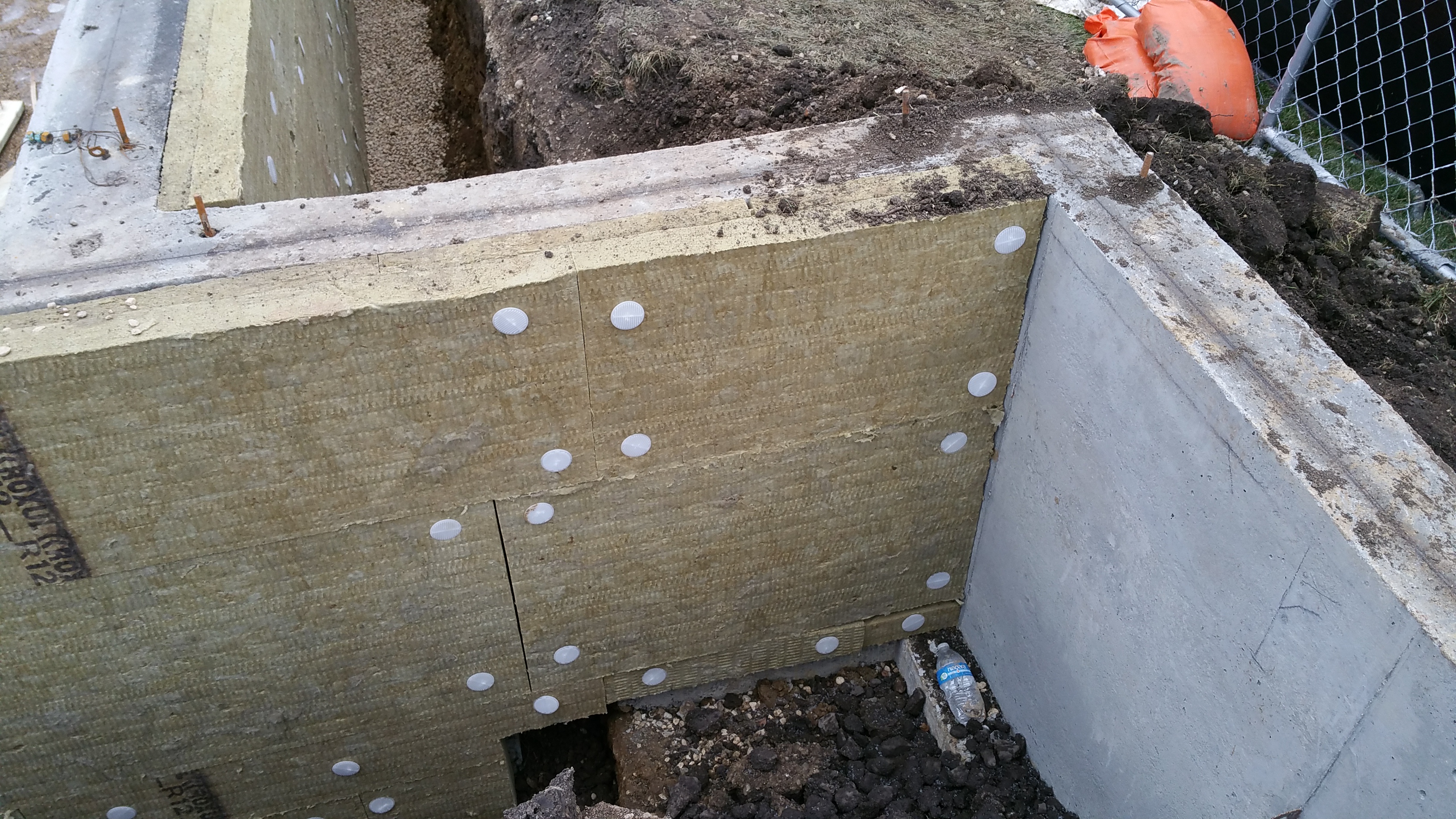
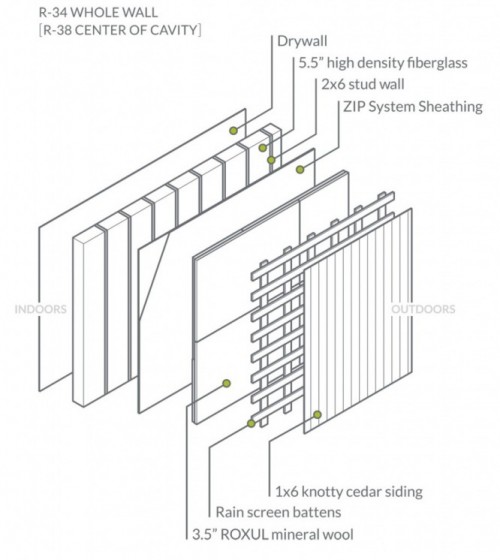
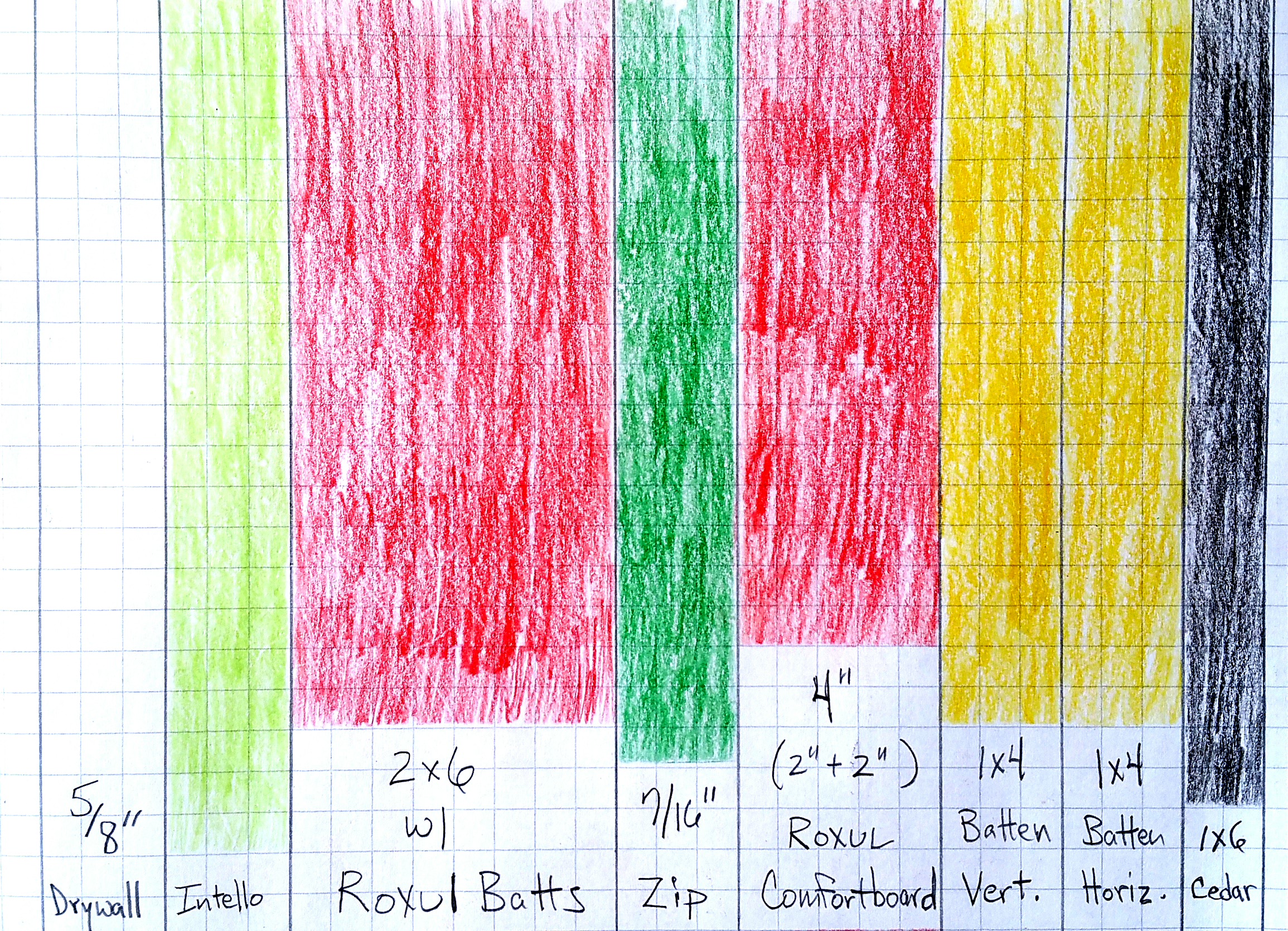
After considering various insulation choices (Wall Assembly), we decided to go with Roxul for under our slab, the exterior of our foundation, and our wall assembly (blown-in cellulose in the attic was the only significant deviation from the use of Roxul).
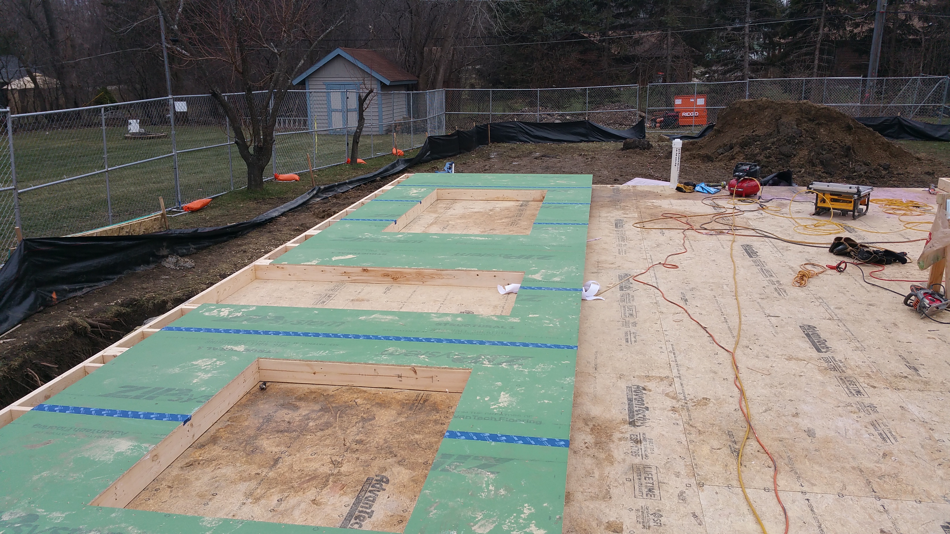
Here’s how the basement slab portion of our project progressed:
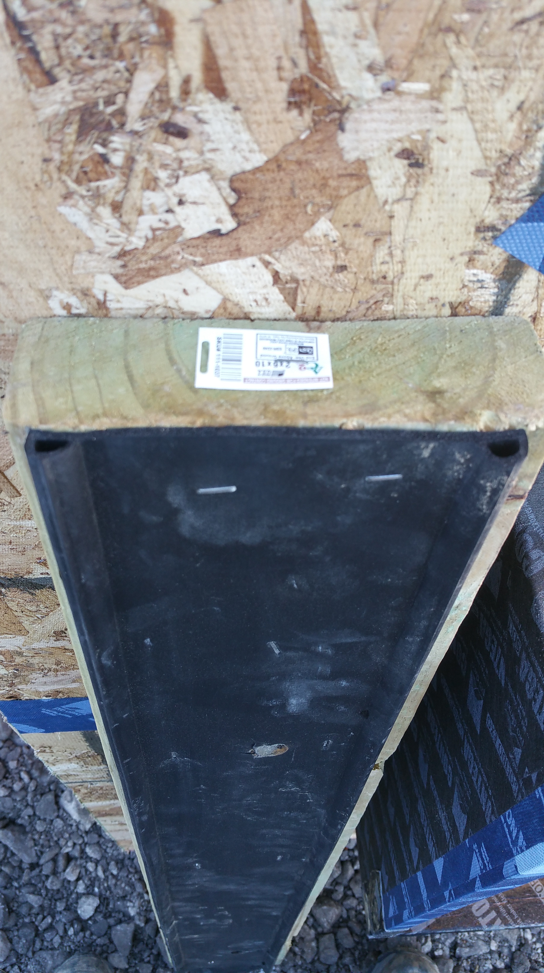
Roxul Comfortboard 80 (2″ + 2″)
To get to an R-value of 16 we used two layers of 2″ thick Roxul Comfortboard 80 (R-4 per inch).
We installed each layer with staggered seams, although the Roxul representative I spoke with via email insisted that because the Roxul is so dimensionally stable this isn’t nearly as important as it would be with rigid foam insulation (the same holds true with a double layer of Comfortboard 80 on the exterior side of wall sheathing).


One of the many benefits of using Roxul is that the material wants to stick to itself, whether in batt or rigid board form. This makes for tighter joints between pieces, and even when cuts around obstructions are less than perfect it’s easy to fill in any gaps with torn apart pieces of Roxul (again, this holds true for both Comfortboard 80 and their version of batt insulation).

Close-up of the Roxul installed around the roughed-in bath PVC pipes.

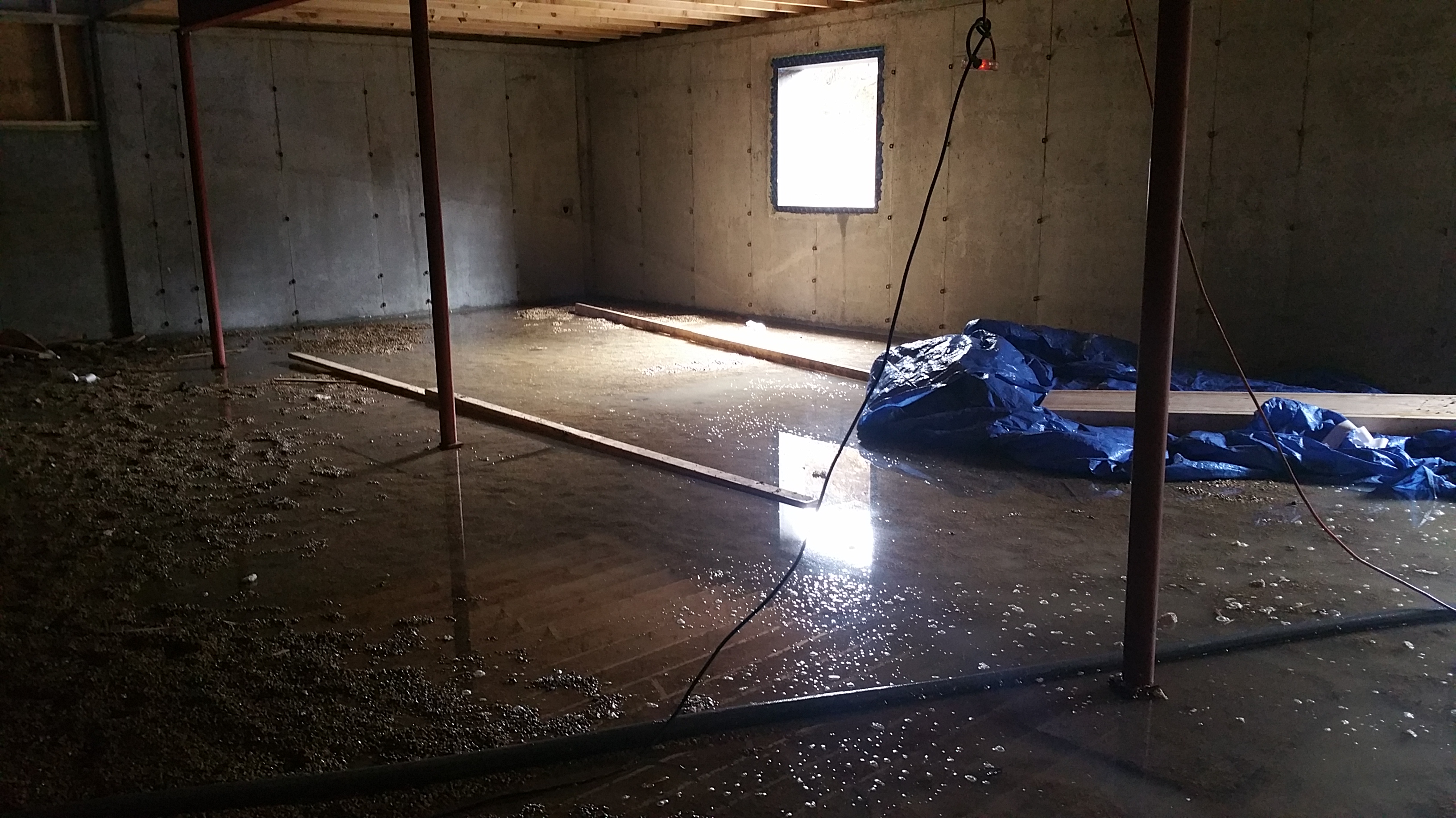
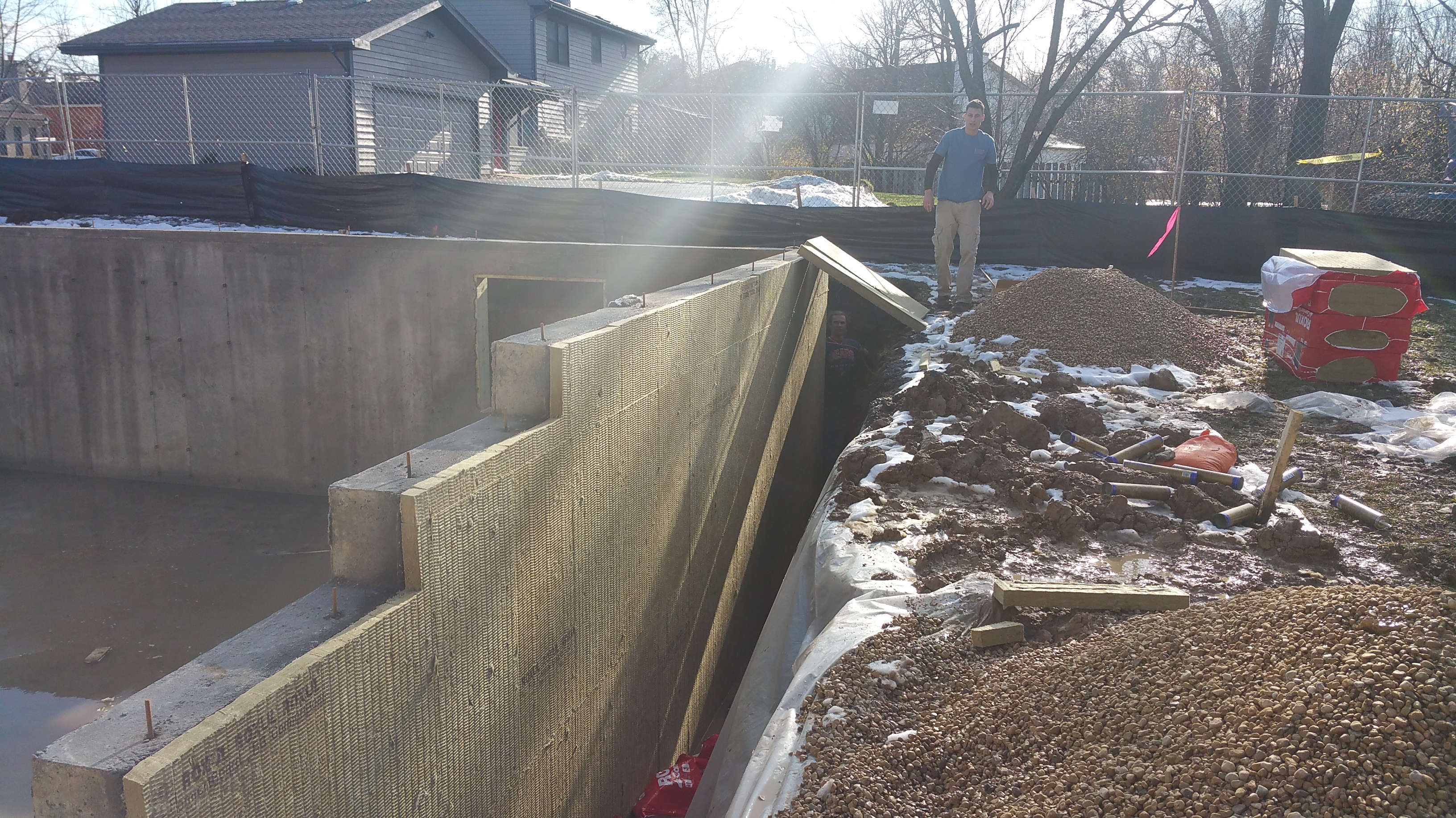
Another view of the 2-layers, mostly installed:

A Roxul rep told me to take into account a loss of R-1 due to the compressive pressure of the poured concrete, thus our R-16 for two layers of Roxul is, according to Roxul, really an R-15. Having installed the two layers myself, walked on it during and after installing the vapor barrier (see below), my guess is in some areas this loss in R-value is even greater than R-1.
Based on the comments quoted in a GBA article (Sub-Slab Mineral Wool), I would have to say my experience was exactly the same: in some areas the Roxul seemed to lose most, if not all, of its rigidity. I’ve also noticed while working with both the Comfortboard 80 and their batts that there seems to be a variation in the material from one piece to another and even bag to bag. Some pieces are very easy to cut (these pieces are noticeably stiffer), while other pieces seem “mushier” or lacking in rigidity — either under or over-cooked perhaps — making them more difficult to cut and work with. This seems like less of an issue for vertical applications (i.e. walls), while potentially troublesome for horizontal applications under a slab — especially if you’re depending on that R-4 per inch to meet the demands of energy modeling for a certification program like Passive House.
I’m glad we’ve been able to mostly avoid foam insulation in the build, but seeing the Roxul in a real world application does make me wonder if some kind of rigid foam might’ve given me a more consistent whole floor R-value. Going with a denser version of Roxul would’ve been another, more expensive, option as well (Comfortboard 110).
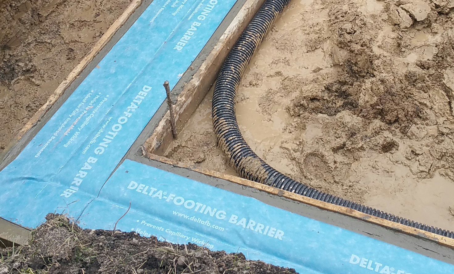
Stego Wrap
Once the two layers of Roxul were down, it was time to install the vapor barrier over the insulation. While the Roxul acts like a blanket, helping to maintain a consistent temperature in the basement, the vapor barrier helps to keep moisture and soil gases (mainly Radon as I understand it), at bay.
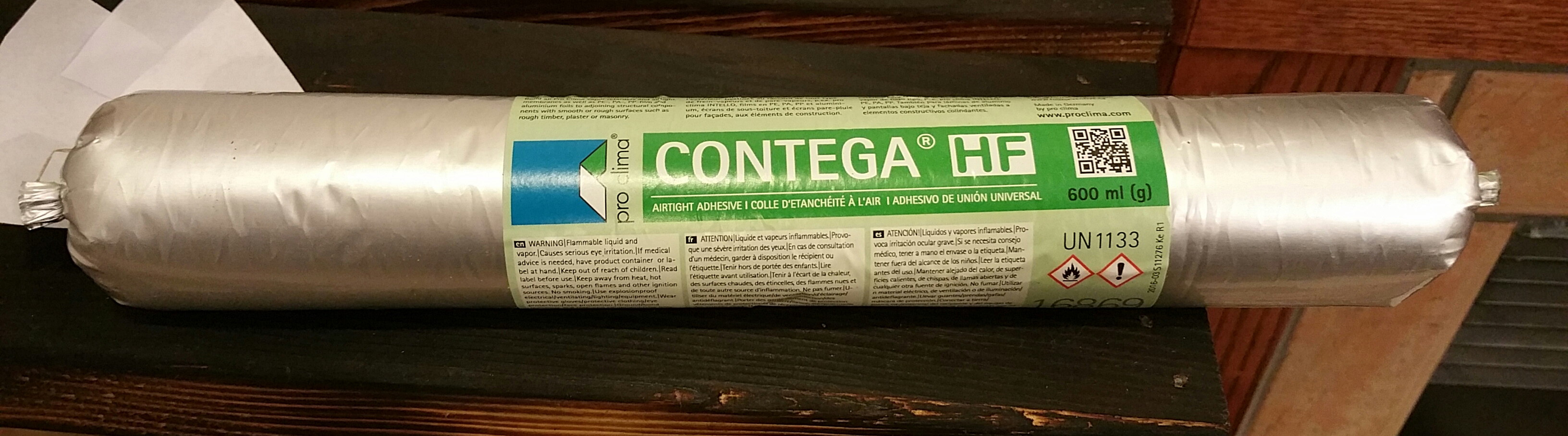
The product I’ve seen used in most Passive House, Pretty Good House, or equivalent projects, is Stego Wrap. Here are two videos detailing its installation and its benefits:
Another product I came across while researching options was Perminator.
Here’s a video detailing the use of the product:
In my area — the suburbs of Chicago — the closest supplier of Stego Wrap was HD Supply.

We used the 10 mil version of the Stego Wrap. The material is very durable and fairly hard to damage. Even when tears occurred, it was easy to patch with pieces of the Stego red tape, or a combination of a cut piece of Stego Wrap with pieces of the red tape.

Installing the two layers of Roxul on the basement floor was pretty straightforward, while installing the Stego Wrap was generally a pain in the ass. Maybe I was just tired, but I really didn’t enjoy installing it at all. For example, it was difficult to keep it tight to the walls, although I learned to leave it hanging fairly loose at floor-wall junctions, which definitely helped. Getting the first row straight, flat, and smooth was time consuming, and annoying, but it did make getting successive rows installed straight much easier.


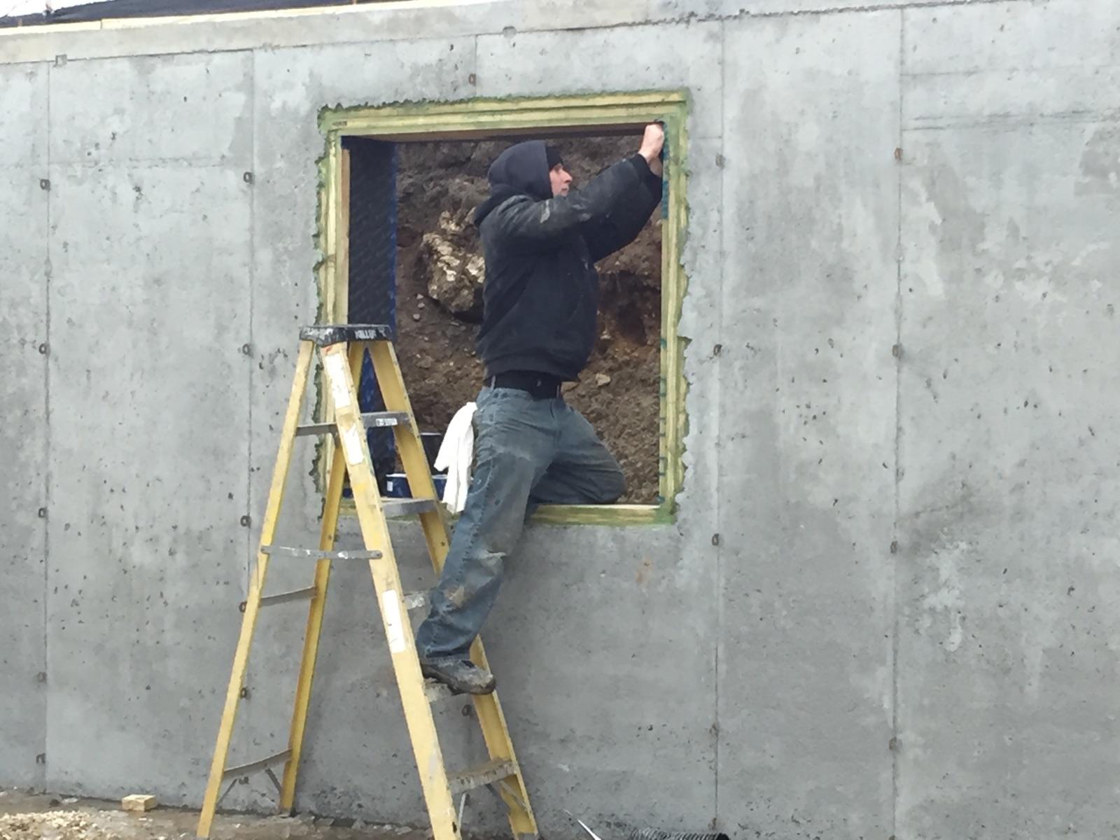
The pipes after air sealing with EPDM gaskets and red Stego tape:

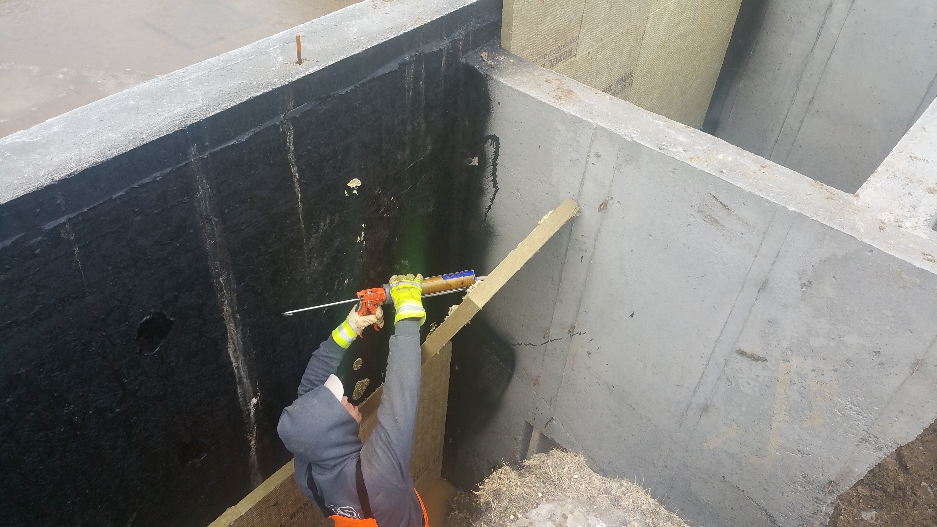
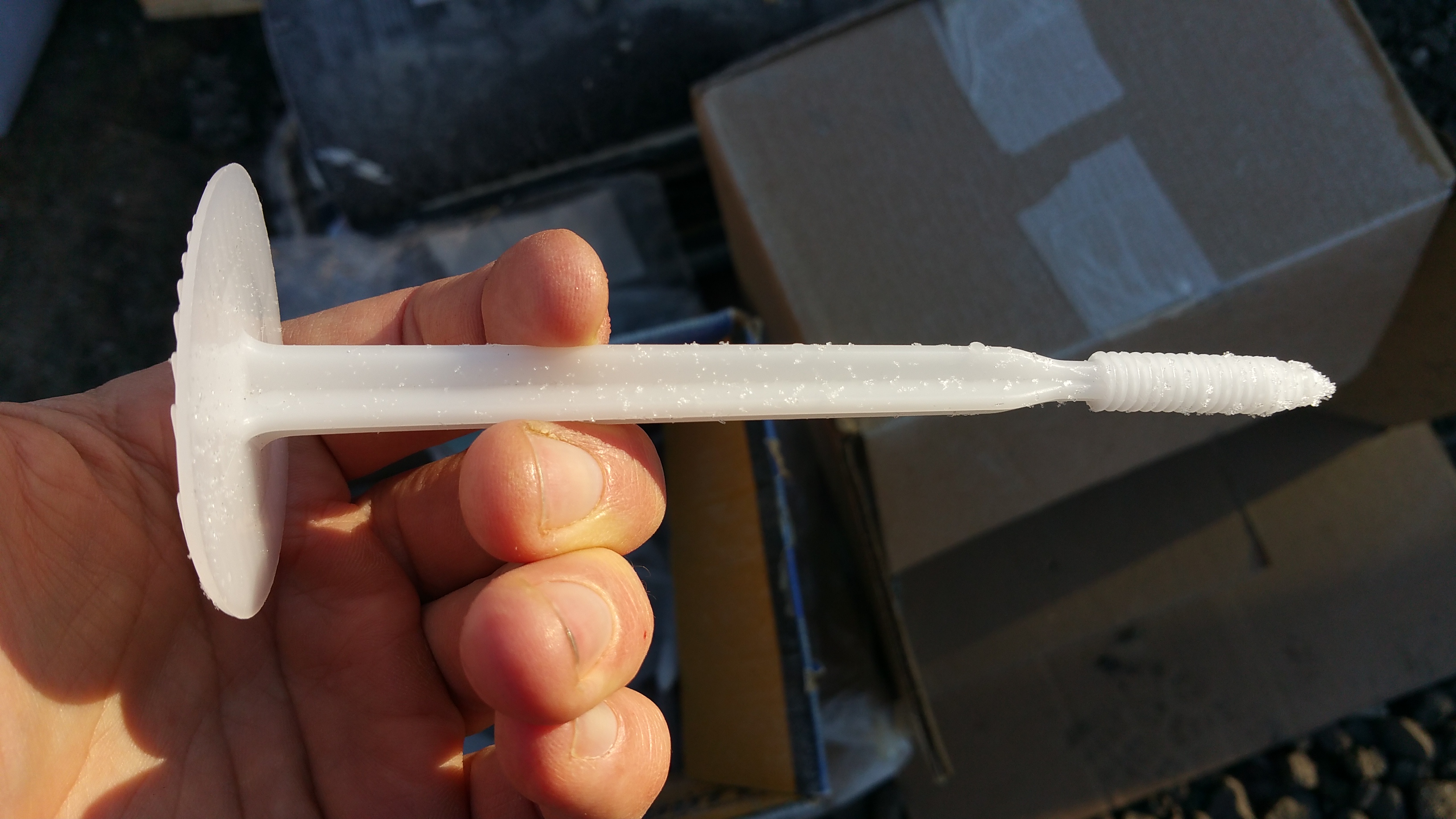
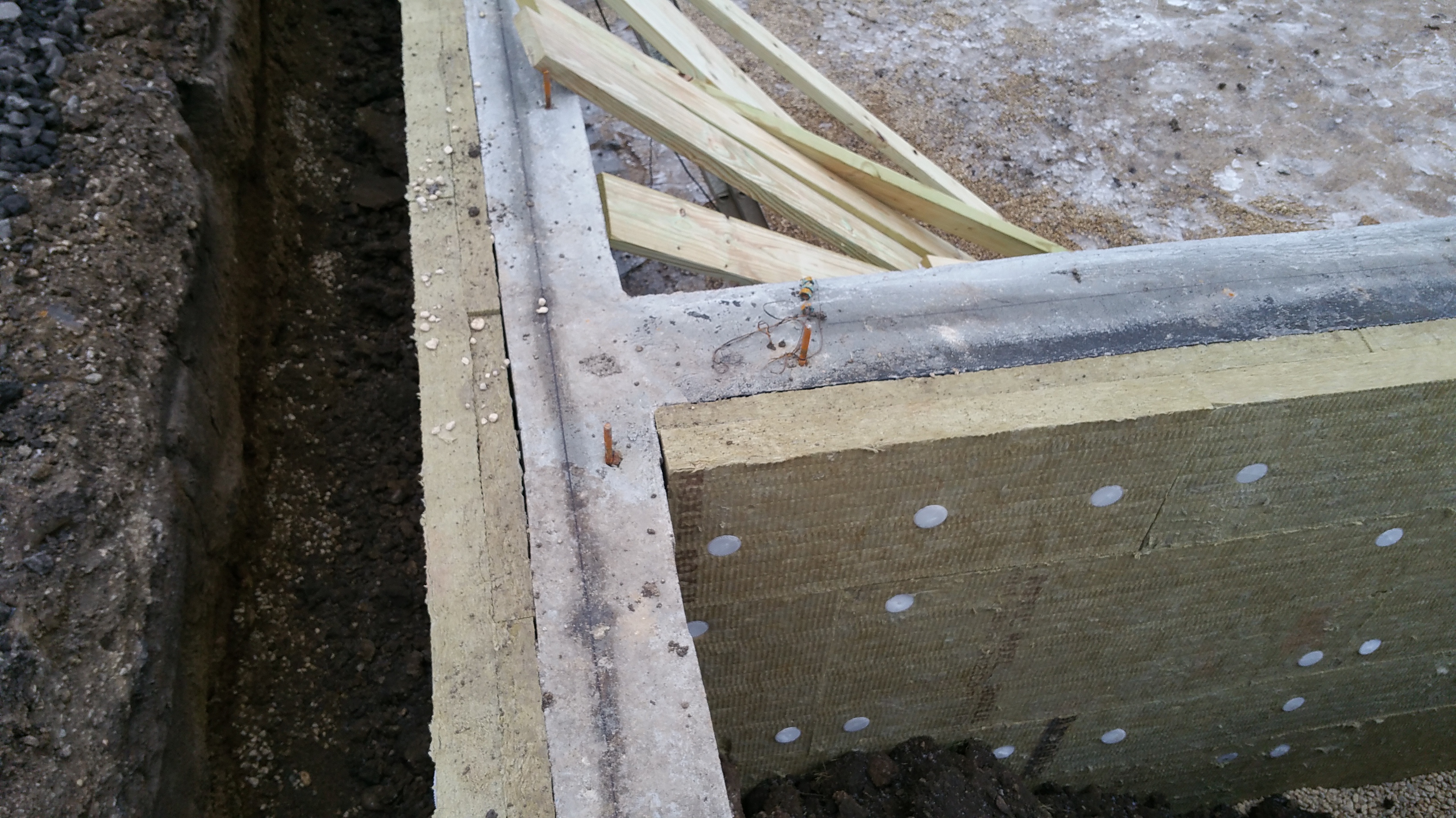
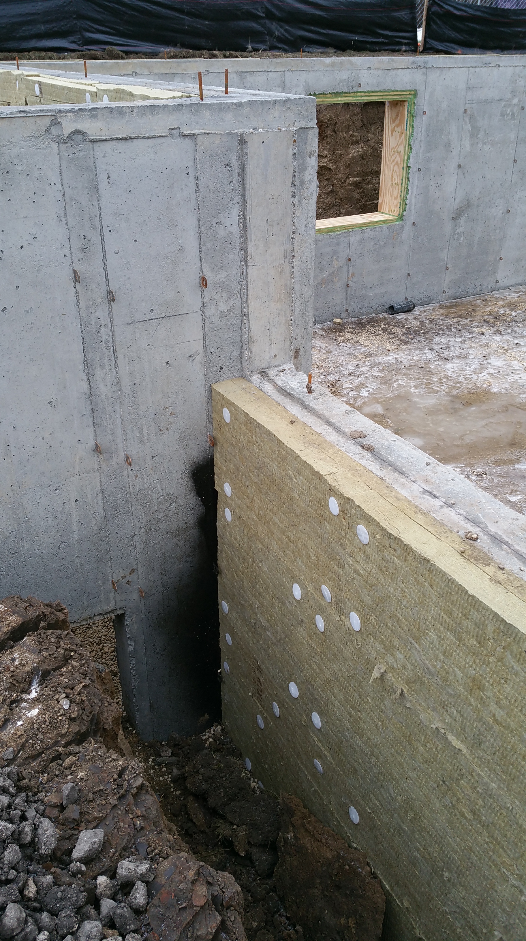
Once all the Stego was in place, we added a 1/2″ of rigid foam insulation at the floor-wall junction as a thermal break. I wanted to use Roxul Comfortboard 80 (their 1.25″ thick version) even for this, but time (Comfortboard 80 is still a special order item in my area, meaning it’s always about 2 weeks away from the time you place your order — hopefully this changes in the near future) and money made the foam an easier choice.

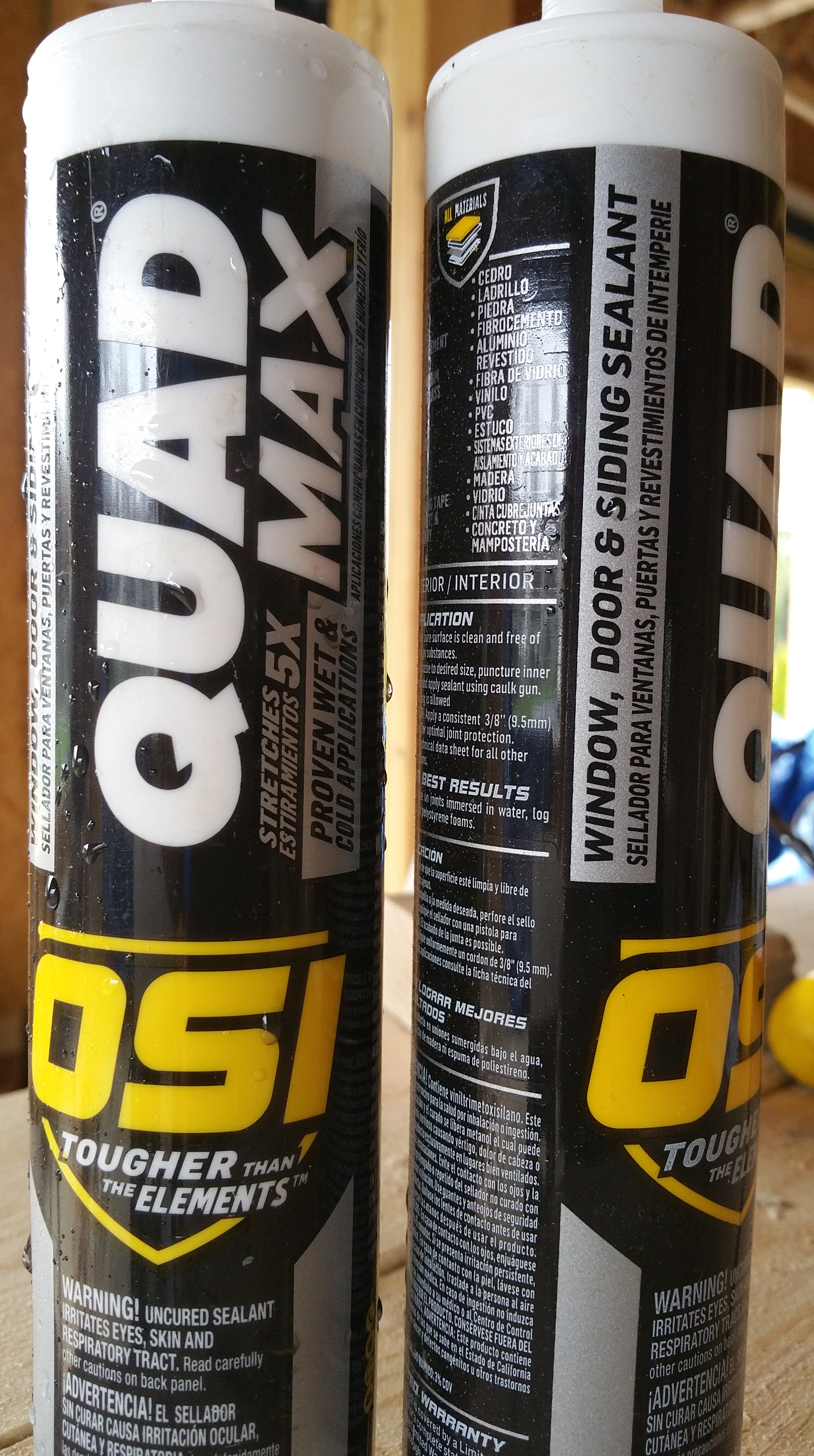
We kept the foam in place by running a bead of OSI sealant on the back of each section before pushing it up against the Stego Wrap. For the most part this seemed to work well.

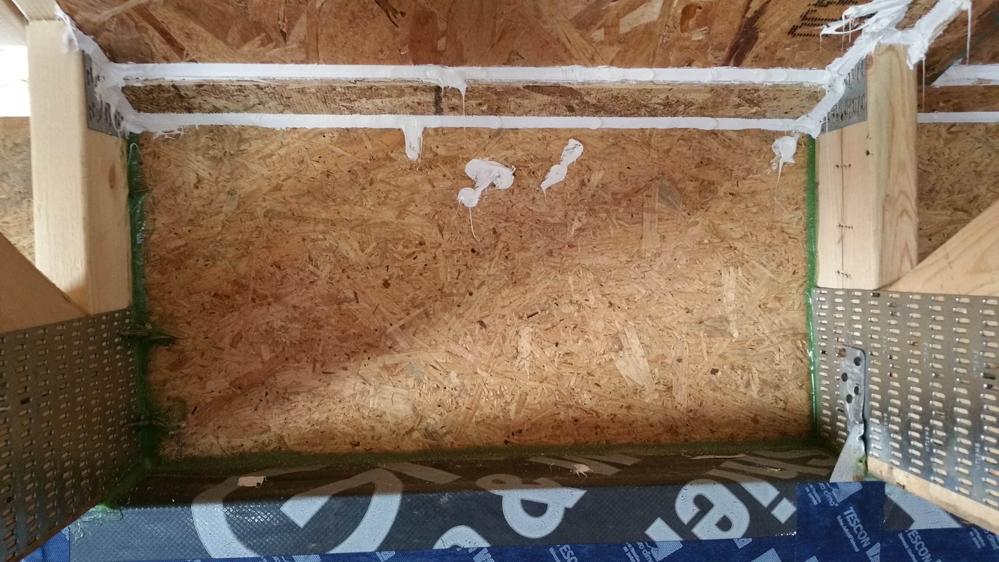
Here’s a close-up of everything installed in a corner:

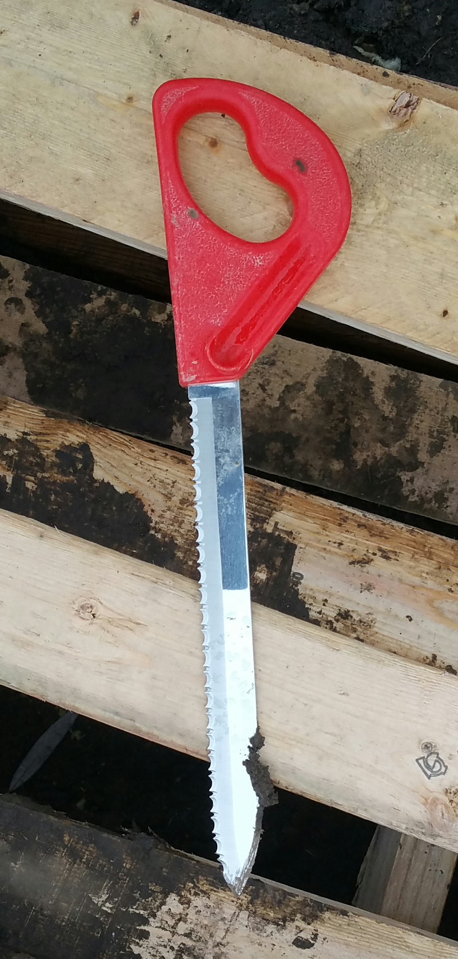
One of the real disappointments of installing the basement slab was seeing the concrete guys put down the welded wire mesh (typically noted as W.W.M. on construction drawings) — basically chicken wire with pointy ends (I exaggerate, but not by much).
If I could do it over again, I would look into using a concrete mix containing sufficient pieces of fiberglass, or some other alternative, so that using the welded wire mesh could be avoided altogether.
I was already familiar with the idea of fiberglass used in place of metal rebar in concrete forms, having experimented with decorative concrete last year and having seen videos like these:
I’m not sure why I didn’t think to ask for fiber reinforced concrete instead of the normal welded wire mesh — it was one detail that just got missed, unfortunately.
As the wire mesh went down, the guys could see how annoyed and concerned I was by the holes it was making in the Stego Wrap that one of them, Oscar, started helping me bend the pointy ends up. Once they were safely pointed up, I went around with the red tape to patch the many tiny holes in the Stego Wrap. Not a fun way to kill a couple of hours.
Why my architect or the concrete guys didn’t suggest a mix with fiberglass instead of the welded wire mesh is unclear. The reality with any green build, especially if you’re acting as GC, is you’re likely to be the only one who really cares about getting the many details right, especially if the architect and subcontractors have never built like this before — they were just doing what they always do.
A couple shots of the basement floor with the welded wire mesh in place:


A closer view with all the elements in place prior to the pour:

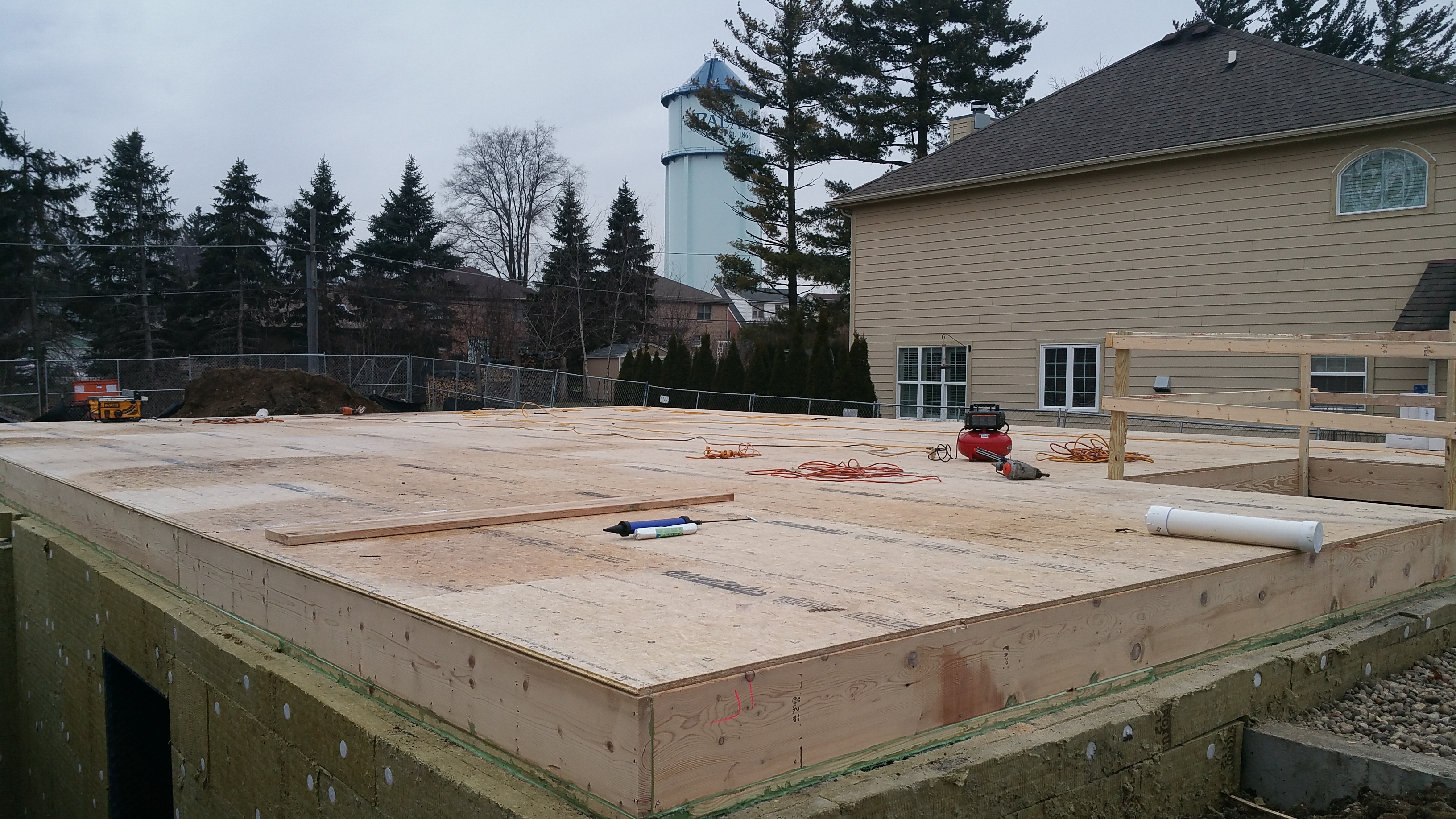
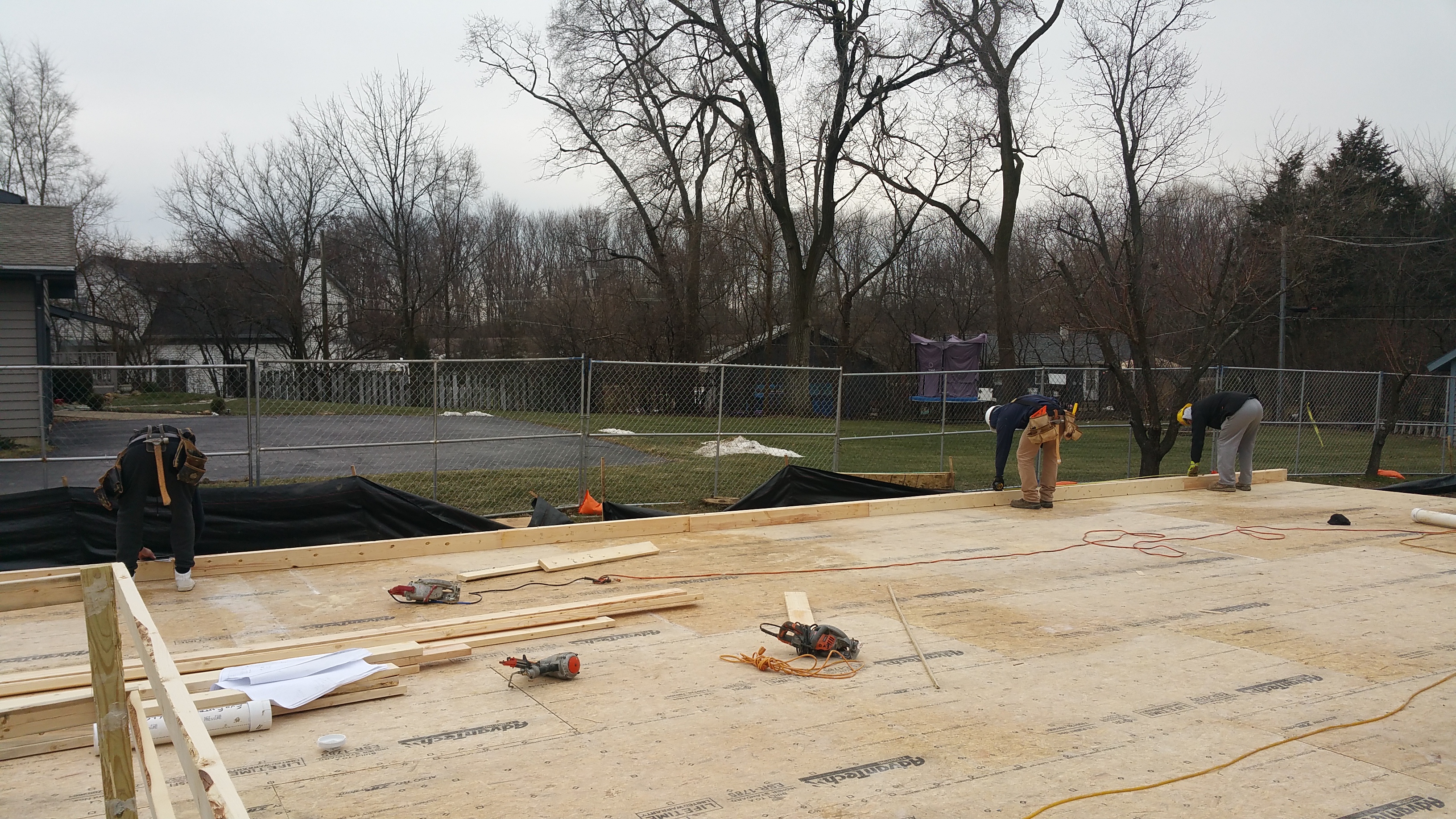
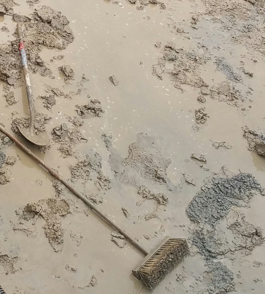
Concrete
Here’s various shots of the slab itself being poured:


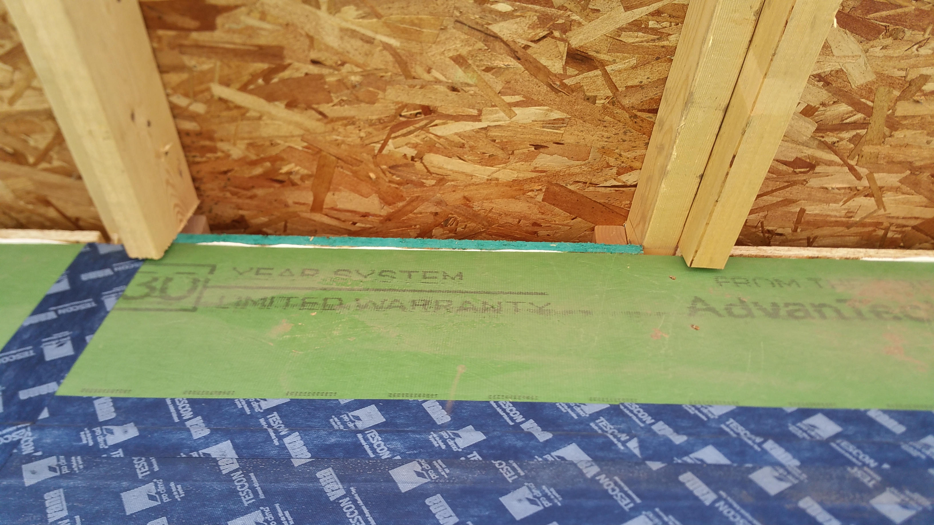
Slab Edge
Once the slab was in place, I wasn’t quite sure how to deal with the edge along the perimeter. As usual when I get stuck on some detail, I asked a question on GBA:
How do I seal…


Using the Prosoco Air Dam seemed like the best, and most straightforward, option. In addition, after considering various ways to cover this gap after the Air Dam was down between the wall and floor, and after priming and painting the basement walls, I realized the gap visually disappears for the most part, and really wasn’t worth thinking about.


By not putting anything down to cover this gap, if the basement ever does experience water damage, it’s one less thing to remove and replace.


You must be logged in to post a comment.