Our attic is designed mainly to hold our blown-in insulation (a future post will go over the details), as opposed to a place for running HVAC equipment, conduit for electric, or as a potential area for carving out additional storage space.
Nevertheless, in order to have access to our attic for future maintenance or repairs, I installed a well-insulated attic hatch in our master bedroom closet ceiling.
Following Passive House and Pretty Good House principles required trying to protect the thermal envelope, even in this relatively small area, in order to avoid what can be a notorious point of air leakage and heat loss (i.e., the stack effect).
There were two main products I considered using for this:
They also have a product that allows for a built-in ladder for easier access to the attic (you won’t need to drag your ladder in from the garage) while also maintaining a high R-value:
We ended up going with the Battic product, which I purchased through the Home Depot website (this saved me a trip to the store since it was delivered to site).
Some other products that I’m aware of include:
475 High Performance Building Supply used to sell a Passive House certified version with a fold-down ladder included, but I don’t currently see it listed on their website:
Because the Energy Guardian hatch is made out of rigid foam, I thought the Battic door was the better choice since it seemed like it would be a little sturdier and more durable. To be honest, once the product arrived and I unpacked it, I realized it was something I, or anyone with basic carpentry skills, could put together themselves (assuming you have the time).
Following the directions, I cut an X in the Intello on the ceiling between two roof trusses (and our 2×6 service core below each truss) in order to establish the opening for the Battic frame.
I folded the cut edges of Intello up into the attic for the two long sides of the Battic frame. For the two shorter sides of the Battic frame it was easier for air sealing to push the Intello down into the living area.
At this point I was able to screw the Battic frame into place.
Battic frame initially installed between roof trusses and 2×6 service core.
Air sealing the Intello to the Battic frame (short side between trusses).
Another view of the Intello sealed to the Battic frame.
View of the installed Battic frame from the attic.
Air sealing the connections between the Intello, the Battic frame, and the roof trusses in the attic.
Using HF Sealant to make the connections as air tight as possible.
Once the outside perimeter of the Battic frame had been air sealed to the Intello, the only place left for air infiltration was where the lid would meet the frame of the Battic hatch once it was installed (more on this later when I discuss my first blower door test).
There was some additional framing required, but it was just a couple of “headers” between the roof trusses to add structural integrity to the two shorter sides of the Battic frame.
Battic frame with additional 2×6’s on one of the short sides.
Since we were using a significant amount of blown-in insulation in the attic, it made it necessary to build up the sides of the Battic frame in the attic with some plywood to get the top of the opening above where the insulation would eventually stop.
Here’s another view of the 3 sides of plywood installed:
The fourth and final side of plywood was installed just prior to blowing in the insulation — in the interim this made getting in and out of the attic much easier.
After a couple of practice attempts, it quickly became apparent that raising and removing the lid once in place, and fighting to get it back down into the master bedroom closet, wasn’t worth the trouble. Instead, I built a small bench in the attic next to the Battic frame so I could push the lid up above the level of blown-in insulation, this way it could have somewhere to safely sit while dealing with any issue in the attic.
Battic lid resting on the bench.
It’s very easy to grab the lid off the bench and bring it back down into position while slowly walking down the ladder in the master bedroom closet to make the final connection/seal.
Although the installation process was fairly straightforward and headache free for the Battic product, if I had it to do over, I think I would have the attic access point on the exterior of the structure, for example, on the gable end of the house in the backyard.
Putting the access point above the air barrier would make meticulously air sealing the entry point for the attic less important, so keeping water out of the attic would be the main goal. An additional plywood buck would’ve been necessary, replicating what I did for our windows and doors (more on this later), but I think it still would’ve been the better option overall.
Putting the attic access on the exterior of the house would also mean avoiding an ugly hole somewhere in our drywalled ceiling. No matter how nicely trimmed out, these attic access points on the interior of a home never look right to me. We’ve tried to hide ours as much as possible by sticking it in our master bedroom closet, which has worked out well, but not having one at all on the interior of the house would make for a cleaner, better solution in my opinion.
If granted a do-over, I would also add a cat walk in the attic through the roof trusses. This would make getting to any point in the attic much easier to navigate. It would also help to avoid disturbing the blown-in insulation too much.
And here’s a photo of the bench in the attic, next to the opening for the Battic attic hatch, after the blown-in insulation was installed:
Sealing the Seams and Penetrations in Zip Sheathing
Note:This post will concentrate on the Zip sheathing itself, as it relates to seams and penetrations. I’ll address how I sealed around openings for windows and doors, along with our attic access hatch through the Intello on the ceiling in separate, future blog posts.
We used Zip sheathing as our WRB (weather resistant barrier — sometimes it’s referred to as a water-resistant barrier) based largely on Hammer and Hand projects:
As the 7/16″ Zip sheathing went up, I taped most of the seams with Pro Clima’s 3″ Tescon Vana tape (available at 475 HPBS), but also their Contega tape(6″ wide), which I used mainly for outside corners and larger seams in the Zip (mainly where the horizontal seam in the Zip transitioned from the exterior walls of 2×6 framing to the roof trusses — shown in a photo later in this post).
My wife and daughter also cut up the Tescon Vana tape into small pieces in order to cover all the nail and screw holes in the Zip sheathing.
The Beast and Eduardo team up to tape the nail and screw holes on the lower sections of Zip sheathing around the house.
The nail holes were initially sealed with HF Sealant, also available from 475 HPBS, thus giving them double coverage — this was discussed earlier, here:
And here’s a good video discussing the Zip sheathing and its benefits (and its place in the evolution of building science):
If I had it to do over, I think I might be tempted to use 1/2″ exterior grade plywood as my sheathing (there are any number of WRB options these days). This would be sealed on the exterior side with either a liquid membrane, like Prosoco’s Cat 5, or a peel-n-stick tape like Henry’s Blue Skin, or even another 475 HPBS product Solitex Mento 1000.
The Zip sheathing works, and the exterior green skin held up nicely during construction, even as it sat exposed for nearly 10 months after we fired our GC’s and struggled to keep the project moving forward. Nevertheless, it is little more than glorified OSB, which comes with certain inherent weaknesses.
Matt Risinger does an excellent job of delineating the cost/benefits of using either OSB or CDX plywood as a sheathing material:
Garage (at left) house (at right) connection. Gap will eventually be filled with 4″ of Roxul Comfortboard 80.
Closer view of this same garage – house connection. Flashing will cover the bottom of the Zip and then carry over the top of the Roxul that covers the foundation.
View of the north side of the house as Tescon Vana tape air seals the nail holes and the seams in the Zip sheathing.
View of the West facade with Tescon Vana tape, along with the black Contega tape at larger seams (e.g. where the walls meet the roof trusses) and outside corners.
West facade as taping proceeds.
Northwest corner of the house, transitioning from the Tescon Vana to the black Contega tape at the corner.
Finishing up some of the final seams in the Zip on the West facade.
Once the Zip was fully installed, it was readily apparent that some of the seams, especially near the base of the first floor where a horizontal seam ran around the entire structure, would need to be tightened up.
Here’s a view looking down on one of these areas where the Zip sheathing did not sit flat against the framing members:
Horizontal seam in Zip sheathing refusing to lie flat against the 2×6 framing members.
Using a 1×4 in each stud bay, I was able to pull the seam in the Zip sheathing together. It wasn’t always perfect, but the difference was visibly significant and in most areas well worth the effort.
Placing a 1×4 into position over the seam in the Zip, I would drive a couple of screws towards the exterior.
1×4 used to pull an unruly seam in the Zip sheathing together.
Screw from the interior poking outside as it initially gets the 1×4 in place.
Once securely attached from the interior, I went outside and drove several screws into the Zip, both above and below the seam in the Zip, to pull the seam tight to the 1×4. At that point, I could go back inside and remove the two screws that were driven towards the exterior.
In addition to air sealing the exterior side of the Zip sheathing, I also invested some time in air sealing the interior side of the Zip as well. Below is a long view of several stud bays with 1×4’s installed, but before air sealing gaps around the 1×4’s and lower areas of the stud bays with HF Sealant.
Long view after applying the HF Sealant:
Close-up of the interior side of the Zip sheathing meeting a 2×6 framing member in a stud bay after applying a thick bead of HF Sealant:
Close-up of lower area of a stud bay after air sealing with the HF Sealant (it transitions from a light to darker green as it dries):
1×4 installed and HF sealant applied to all gaps and screw/nail holes in the stud bay.
I held off on using the HF Sealant at the wall sill plate/subfloor connection until just prior to installing the Intello on the walls since this area constantly attracts dirt and debris.
Sealing on the interior side with HF Sealant, even between vertical framing members, means that even if there are any weaknesses in either the Zip sheathing or the Tescon Vana tape at these points, air won’t find an easy way in, since it will be blocked from the interior side as well (there won’t be a difference in air pressure to help the outdoor air make its way indoors).
This kind of redundancy in air sealing should give the house long-term protection against air leaks, thereby aiding the long-term durability of the structure, as well as making it a much more comfortable environment to live in.
Using HF Sealant between vertical framing members.
I also spent some time on the roof trusses, sealing around nails, the top plates of the exterior walls, and the many Zip-framing member connections in what will eventually be the attic.
Sealing around fasteners and framing in the attic with HF Sealant.
This had less to do with air sealing and more to do with preventing any potential water intrusion since this area is technically above our ceiling air barrier (the Intello), which is detailed here:
This proved helpful when explaining to the various subs how to help me protect the air barrier — especially when it came time to drill holes through the Zip sheathing. Of particular importance was making holes closer to the center of a stud bay, as opposed to hugging a corner or side of one of the 2×6 framing members. A hole cut too close to a stud or a roof truss is much harder to properly air seal.
Interior side of our mock wall assembly showing how all penetrations through the Zip should be in the middle of our framing members. Our original plumber was the only trade that managed to screw this up (it’s no coincidence that he was also the only sub that we had to fire).
In effect, any time a sub had to make a penetration through the air barrier we discussed the details, and once the cut was made I immediately air sealed the penetration both on the exterior and interior side.
By sealing each hole in the Zip on both sides, again I hope it ensures the long-term durability of the overall structure. The main argument for this strategy assumes the exterior side of the sheathing will face more extreme temperatures, and fluctuations in humidity, and presumably even wind-drive rain if/when it gets past the siding and 4″ of Roxul insulation, putting it at greater risk of failure (especially in the long term). By taking the time to air seal the interior side, it just gives the overall air barrier, and therefore the structure, a better chance at avoiding air and water intrusion (that’s the goal anyway).
For air sealing I used a mix of tapes, HF sealant (later even some Prosoco products), EPDM Roflex gaskets, and duct seal.
The penetrations for electric service were my first go at using the Roflex gaskets:
John and Danny installing the electric meter.
The smaller diameter Roflex gasket comes with its own Tescon Vana tape, which makes installation straightforward.
Electric meter with Tescon Vana – Roflex gaskets installed.
Exterior view of electric Meter air sealed with gaskets and Tescon Vana tape:
Once sealed on the exterior side, I went inside to seal the penetrations for a second time:
Air sealing the electric meter on the interior side.
It was a big moment when the electric panel went in:
The house is ready for power.
The installation of our solar panels required air sealing two penetrations — one through the Intello on the ceiling on the inside of the structure, along with one exterior penetration through the Zip:
Details regarding the installation of our Solar array can be found here:
Solar disconnect (on/off) with its Tescon Vana gasket.
We also had two frost-free hose bibs, or sill cocks, installed, which also required gaskets on the exterior and interior sides of the Zip sheathing.
Frost free hose bib with gasket.
One of the big advantages a Roflex gasket has over using a sealant like the green HF Sealant, or Prosoco’s Joint and Seam, is the pipe can be moved in and out even after air sealing, which is especially helpful for installing siding later.
We left the sill cocks loose (unconnected to water supply line inside the house), allowing the siding guys to adjust in and out for a more precise fit of the charred cedar siding.
Below is an example of what conduit through the Zip sheathing looks like before it gets a gasket and some tape:
Penetration for conduit before gasket.
And here’s the conduit after the gasket and some tape:
Conduit after gasket.
Note the extended length of the conduit, anticipating our 4″ of Roxul covering the Zip, 2-layers of furring strips (vertical then horizontal — for vertically oriented siding), and the eventual charred cedar siding.
The photo below shows the penetrations, along with multiple lines of conduit, for our eventual ductless mini-split Mitsubishi heat pump system. The empty hole will be our disconnect for the heat pump. I’ll go into the details of our ductless mini-split system in a future post.
Penetrations for our Mitsubishi heat pump system.
Same series of conduit pipes after gaskets and being connected to the compressor outside:
In addition to the conduit for electrical hook-up, the Mitsubishi heat pump system required a separate penetration for running the refrigerant lines to the compressor:
Hole cut for the heat pump refrigerant lines.
After discussing it with Mike from Compass Heating and Air, who did our ductless mini-split installation, we decided to use a 4″ section of PVC plumbing pipe as our “conduit” for running the refrigerant lines from the interior of the structure to the outside:
4″ PVC plumbing pipe for the refrigerant lines.
After the PVC was passed through the hole in the Zip, we added a 2×4 underneath it to give it some added stability, along with the usual gasket and tape for air sealing around the PVC pipe:
Before applying Tescon Vana around the Roflex gasket.
Once the refrigerant lines were passed through the PVC pipe, it was clear that some additional air sealing was required.
PVC pipe with refrigerant lines installed.
I filled the gaps around the refrigerant lines from the interior and exterior sides with duct seal. Before stuffing in the duct seal at either end of the PVC pipe, I added bits of Roxul Comfortboard 80 into the pipe to try and give added R-value to the interior of the PVC pipe (hoping to prevent any possible condensation from forming inside the pipe).
A real lifesaver when it comes to air sealing. Readily available at big box stores, or online at Amazon.
Duct seal proved especially helpful at air sealing multiple weak points in the structure —areas that would’ve been difficult or impossible to air seal with just tape, gaskets, or sealants:
Using duct seal to block off air from the interior side.
Another view of the PVC pipe with duct seal.
The refrigerant lines transitioning from the basement ceiling to the PVC pipe before leaving the structure.
Once the interior was taken care of, I was able to address the exterior side of the PVC pipe:
Exterior view of the PVC pipe with heat pump refrigerant lines exiting the structure. Air sealed with a Roflex gasket and duct seal inside the pipe.
Again, note that the PVC pipe is extended out in preparation for the layers of exterior insulation, furring strips, and siding:
Same area after completing the air sealing with Tescon Vana tape.
And here’s a view of the same area after the siding was installed (I’ll go into the many details regarding the installation of the exterior insulation, furring strips, and siding in a future post):
Air sealing for the refrigerant lines complete after the siding is installed.
Additional areas where the duct seal proved to be invaluable:
Exterior electrical boxes for lights and outlets.
Conduit for the water meter in the basement (only the interior is shown below, but the conduit was air sealed with duct seal on the exterior end as well):
And here’s the same conduit for the water meter as it leaves the house on the first floor:
Conduit for the water meter, air sealed on both sides of the Zip with the Roflex/Tescon Vana gasket.
I also had to address the disconnect boxes for our solar array and our heat pump. For instance, here’s our solar disconnect box when it’s open:
And here it is after removing the pull out switch, revealing an air leak:
Close-up of the conduit:
An even closer look:
And here it is after being air sealed with the duct seal:
I did the same air sealing for the Mitsubishi heat pump disconnect box:
Close-up of the conduit sealed with the duct seal:
During my initial blower door test (more on that later), some air movement around the main panel in the basement was detected, so when the electrician came back we added duct seal to the main pipe entering the house (it had already been sealed from the exterior side with duct seal):
Close-up view of the main panel from the interior where lines first enter the structure.
Besides the penetrations in the Zip sheathing, there were other penetrations through the Intello (our air barrier on the ceiling) that had to be addressed as well. These areas were air sealed with the same set of products as the Zip.
For example, in addition to the conduit for solar through the Intello, we also had to air seal conduit for electric service to the attic (for a light and switch in the attic), in addition to the the penetrations for radon and plumbing waste vents, some of which are shown below:
Plumbing waste vent going into the attic.
Another view of this vent pipe after air sealing, this time from below:
Here is one of the vents that our first, incompetent plumber installed too close to one of the 2×6’s used to establish our service core:
Installed this close to framing makes air sealing the vent needlessly complicated and frustrating.
Here’s the same area after applying the Tescon Vana tape:
Below is another vent pipe incorrectly installed too close to a 2×6. This one was even more challenging to air seal properly. After the gasket and Tescon Vana, I added the green HF sealant as insurance against air leaks, both for now and in the future.
We also had to air seal the penetrations for our Zehnder Comfo-Air 350 ERV ventilation unit. I’ll go into the details of the actual installation later, but here are some photos of the penetrations through the Zip sheathing and how we addressed making them air tight:
First section of Comfo pipe going through the Zip sheathing.
The gray Zehnder Comfo pipe (for supply air stream) exiting the structure with a Roflex gasket.
Closer view of the Comfo pipe air sealed with a gasket and Tescon Vana tape.
An even closer view of this same area where pipe meets gasket and tape.
We followed the same process — Roflex gasket and Tescon Vana tape — for the exterior side of the Zehnder Comfo pipe:
Zehnder Comfo pipe installed, air sealed, and ready for commissioning.
And here’s a picture of both supply and exhaust pipes for the Zehnder:
Supply pipe in the background, exhaust in the foreground. The garbage bags keep out weather and animals until after the siding is up and the permanent covers can be installed.
During my initial blower door test some air movement around the sump pit was detected.
Sump pit lid sealed with duct seal, Roflex gasket with Tescon Vana, and the seam between the pit and lid sealed with Prosoco Air Dam.
The sump pump discharge pipe also needed to be air sealed on both sides of the Zip:
Sump discharge pipe sealed first with Prosoco Joint and Seam, then a Roflex gasket, before applying Tescon Vana tape around the gasket.
Some air movement around the ejector pit was also detected, so I used duct seal to try and block it.
Ejector pit air sealed with duct seal.
For low voltage — in our case, a cable TV/Internet connection — we found a utility box at Lowe’s (also available at Home Depot and Amazon), and combined it with conduit to transition from the exterior to the interior. The diameter of the conduit is large enough to allow wires for other utilities/services to pass through as well, if necessary, in the future.
Cable box installed after the siding went up.
An engineer from Comcast-Xfinity visited the site back in the summer, and he gave me the go-ahead for using this box/conduit set-up:
Closer view of the cable box.
The cable wire exiting the house through the conduit, which is air sealed with duct seal.
Cable wire on the interior of the house exiting through the Roxul insulation and Zip sheathing via the conduit and then air sealed from the interior with duct seal.
Even the wire for the doorbell was sealed with a gasket and tape:
When the weather warmed up I was able to experiment with the Prosoco R-Guard series of products (note the 3/4″ plywood door buck treated with Joint and Seam and Fast Flash). I’ll go into that more when I discuss prepping for the windows and doors later.
A closer view of the doorbell gasket.
Air sealing the penetrations was challenging at times, but also a lot of fun — always keeping in mind the goal of meeting the Passive House standard of 0.6 ACH@50 for our blower door test.
Hopefully this inventory of penetrations will prove helpful to someone in the planning stages of their own “air tight” build. It always helps seeing how other people do things — in particular, the strategies they employ and the specific products they use.
Seeing these real world examples of air sealing around the many penetrations in a structure will hopefully give others the confidence to come up with their own plan of attack for building an airtight structure.
Following Passive House principles, we knew we were going to insulate and air seal our basement slab. As explained on the Passipedia website:
“The most important principle for energy efficient construction is a continuous insulating envelope all around the building… which minimises heat losses like a warm coat. In addition to the insulating envelope, there should also be an airtight layer… as most insulation materials are not airtight. Independently of the construction, materials or building technology, one rule is always applicable: both insulation and airtight layers need to be continuous.”
The illustration above also shows the “red pen test”, which is supposed to occur in the design phase of a project, when it’s much easier to address weaknesses or errors in the details of a design — not necessarily just for air sealing, it’s also effective when looking for points of potential water intrusion (e.g., this GBA article), or even to test the thermal layer for areas of thermal bridging. The basic idea is that if your layers aren’t continuous you’ll find yourself lifting your red pen, meaning it’s an area that needs to be addressed.
An effective way of thinking about a structure, utilized by high-performance builders, is to think in terms of 6 sides rather than just 4 when contemplating the details for air sealing and insulating: 4 walls, the attic/roof, and the basement (or frost-protected slab).
A similar approach to Passive House for building high-performance structures is adopted by advocates of The Pretty Good House concept, even if it’s less stringent, more open to interpretation, and tends to be more “rule of thumb” rather than energy model driven (e.g. PHPP or WUFI).
Based on our climate region, which is Zone 5, we decided we wanted to shoot for 16/20/40/60 for insulation R-values — the series of numbers represent R-values for under the basement slab/ the exterior foundation walls/ framed exterior walls/ and the attic (our attic R-value proved to be significantly higher than 60, but more on that later) — which is in the ballpark for both PGH and Passive House (here’s an excellent overall summary of the PH concept I recently came across: EcoCor).
Arguably, the “sweet spot” for how much insulation makes sense for these areas, even when adjusted for climate region, is still a topic for heated debate. Nevertheless, it’s important to keep in mind that the more simplethe form your structure takes — for example, 2-story cubes without basements —
the easier it is to achieve Passive House, or similar building standards, since it simplifies framing, air sealing, and limits the exterior surface area in ways that a single story ranch that is spread out and has all kinds of nooks and crannies does not (the difference also has serious ramifications for overall heating and cooling demand). Likewise, simple forms also make it easier to figure out how much insulation you need to reach a benchmark like Passive House or PGH. A simple form can also have durability implications.
Our R-values were based on a number of considerations: the construction drawings of our original builder, information made available by Hammer and Hand (in particular their Madrona House project), and articles on the Building Science Corporation (in particular: 1 and 2) and Green Building Advisor websites. These resources, all of which have proven to be indispensable at every stage of the build, have made our project possible.
In terms of the details around the slab and the foundation walls, this article from the DOE also proved to be especially helpful: Foundation Handbook
Illustration courtesy of: foundation handbook.ornl.gov
After considering various insulation choices (Wall Assembly), we decided to go with Roxul for under our slab, the exterior of our foundation, and our wall assembly (blown-in cellulose in the attic was the only significant deviation from the use of Roxul).
Here’s how the basement slab portion of our project progressed:
Roxul Comfortboard 80 (2″ + 2″)
To get to an R-value of 16 we used two layers of 2″ thick Roxul Comfortboard 80(R-4 per inch).
We installed each layer with staggered seams, although the Roxul representative I spoke with via email insisted that because the Roxul is so dimensionally stable this isn’t nearly as important as it would be with rigid foam insulation (the same holds true with a double layer of Comfortboard 80 on the exterior side of wall sheathing).
Putting down the 2 layers of Roxul Comfortboard 80 with help from the concrete guys.
The second layer of Roxul being installed.
Installing the Roxul around the rough-in bathroom pipes, sump, and ejector pits.
One of the many benefits of using Roxul is that the material wants to stick to itself, whether in batt or rigid board form. This makes for tighter joints between pieces, and even when cuts around obstructions are less than perfect it’s easy to fill in any gaps with torn apart pieces of Roxul (again, this holds true for both Comfortboard 80 and their version of batt insulation).
Stuffing bits of Roxul around the base of one of the steel columns.
Close-up of the Roxul installed around the roughed-in bath PVC pipes.
Another view of the 2-layers, mostly installed:
A Roxul rep told me to take into account a loss of R-1 due to the compressive pressure of the poured concrete, thus our R-16 for two layers of Roxul is, according to Roxul, really an R-15. Having installed the two layers myself, walked on it during and after installing the vapor barrier (see below), my guess is in some areas this loss in R-value is even greater than R-1.
Based on the comments quoted in a GBA article (Sub-Slab Mineral Wool), I would have to say my experience was exactly the same: in some areas the Roxul seemed to lose most, if not all, of its rigidity. I’ve also noticed while working with both the Comfortboard 80 and their batts that there seems to be a variation in the material from one piece to another and even bag to bag. Some pieces are very easy to cut (these pieces are noticeably stiffer), while other pieces seem “mushier” or lacking in rigidity — either under or over-cooked perhaps — making them more difficult to cut and work with. This seems like less of an issue for vertical applications (i.e. walls), while potentially troublesome for horizontal applications under a slab — especially if you’re depending on that R-4 per inch to meet the demands of energy modeling for a certification program like Passive House.
I’m glad we’ve been able to mostly avoid foam insulation in the build, but seeing the Roxul in a real world application does make me wonder if some kind of rigid foam might’ve given me a more consistent whole floor R-value. Going with a denser version of Roxul would’ve been another, more expensive, option as well (Comfortboard 110).
Stego Wrap
Once the two layers of Roxul were down, it was time to install the vapor barrier over the insulation. While the Roxul acts like a blanket, helping to maintain a consistent temperature in the basement, the vapor barrier helps to keep moisture and soil gases (mainly Radon as I understand it), at bay.
The product I’ve seen used in most Passive House, Pretty Good House, or equivalent projects, is Stego Wrap. Here are two videos detailing its installation and its benefits:
Another product I came across while researching options was Perminator.
Here’s a video detailing the use of the product:
In my area — the suburbs of Chicago — the closest supplier of Stego Wrap was HD Supply.
Starting around the rough-in bathroom pipes.
We used the 10 mil version of the Stego Wrap. The material is very durable and fairly hard to damage. Even when tears occurred, it was easy to patch with pieces of the Stego red tape, or a combination of a cut piece of Stego Wrap with pieces of the red tape.
Stego Wrap carried up the wall and taped to keep it in place during the pour.
Installing the two layers of Roxul on the basement floor was pretty straightforward, while installing the Stego Wrap was generally a pain in the ass. Maybe I was just tired, but I really didn’t enjoy installing it at all. For example, it was difficult to keep it tight to the walls, although I learned to leave it hanging fairly loose at floor-wall junctions, which definitely helped. Getting the first row straight, flat, and smooth was time consuming, and annoying, but it did make getting successive rows installed straight much easier.
Jesus helping me install the first row of Stego Wrap.
Making progress with the Stego Wrap.
Stego Wrap wth red Stego tape and a Roflex gasket from 475 HPBS.
The pipes after air sealing with EPDM gaskets and red Stego tape:
Once all the Stego was in place, we added a 1/2″ of rigid foam insulation at the floor-wall junction as a thermal break. I wanted to use Roxul Comfortboard 80 (their 1.25″ thick version) even for this, but time (Comfortboard 80 is still a special order item in my area, meaning it’s always about 2 weeks away from the time you place your order — hopefully this changes in the near future) and money made the foam an easier choice.
We kept the foam in place by running a bead of OSI sealant on the back of each section before pushing it up against the Stego Wrap. For the most part this seemed to work well.
Roxul, Stego Wrap, and foam installed.
Here’s a close-up of everything installed in a corner:
One of the real disappointments of installing the basement slab was seeing the concrete guys put down the welded wire mesh (typically noted as W.W.M. on construction drawings) — basically chicken wire with pointy ends (I exaggerate, but not by much).
If I could do it over again, I would look into using a concrete mix containing sufficient pieces of fiberglass, or some other alternative, so that using the welded wire mesh could be avoided altogether.
I was already familiar with the idea of fiberglass used in place of metal rebar in concrete forms, having experimented with decorative concrete last year and having seen videos like these:
I’m not sure why I didn’t think to ask for fiber reinforced concrete instead of the normal welded wire mesh — it was one detail that just got missed, unfortunately.
As the wire mesh went down, the guys could see how annoyed and concerned I was by the holes it was making in the Stego Wrap that one of them, Oscar, started helping me bend the pointy ends up. Once they were safely pointed up, I went around with the red tape to patch the many tiny holes in the Stego Wrap. Not a fun way to kill a couple of hours.
Why my architect or the concrete guys didn’t suggest a mix with fiberglass instead of the welded wire mesh is unclear. The reality with any green build, especially if you’re acting as GC, is you’re likely to be the only one who really cares about getting the many details right, especially if the architect and subcontractors have never built like this before — they were just doing what they always do.
A couple shots of the basement floor with the welded wire mesh in place:
A closer view with all the elements in place prior to the pour:
Concrete
Here’s various shots of the slab itself being poured:
It was necessary to cut a hole in the subfloor just inside the front door in order to get the concrete into the basement.
The guys starting at the back of the basement.
One corner complete.
Enrique completing the trowel finish.
Side of the garage kissed by the cement truck.
Close.
Really close.
Slab Edge
Once the slab was in place, I wasn’t quite sure how to deal with the edge along the perimeter. As usual when I get stuck on some detail, I asked a question on GBA:
Close-up of the wall-slab junction after cutting everything down flush with the floor.
Using the Prosoco Air Dam seemed like the best, and most straightforward, option. In addition, after considering various ways to cover this gap after the Air Dam was down between the wall and floor, and after priming and painting the basement walls, I realized the gap visually disappears for the most part, and really wasn’t worth thinking about.
Junction between wall and slab after using Air Dam and priming and painting the wall.
Close-up of Air Dam after primer and paint, at the wall-slab connection.
Another view of the slab – wall connection.
By not putting anything down to cover this gap, if the basement ever does experience water damage, it’s one less thing to remove and replace.
We thought about using the Zip sheathing as our air barrier on the ceiling, attaching it to the bottom of the roof trusses, something I had seen on other builds, but after learning about Intello we decided to use that instead:
Floris Keverling Buisman, from 475 High Performance Building Supply, did our WUFIanalysis for us, and he suggested the Intello would be a better fit for our project. The Intello is a smart vapor retarder, so it can expand and contract when it’s needed, and it’s obviously less physically demanding to install than the Zip sheathing.
Once the air sealing was complete around the top of our outside perimeter walls, and the insulation chutes had been installed, we were almost ready for the Intello. At the gable ends of the house, one last detail needed to be put in place, circled in red in the picture below:
2×6 on its side, circled in red.
By adding this 2×6 on its side, which is in the same plane as the bottom of the roof trusses, it makes it possible to carry the Intello over the transition from the ceiling (under the roof trusses) to the walls (top plates). This is one of those details that is hard to ‘see’ when in the planning, more abstract, and two dimensional phase of designing a structure.
Another view of the 2×6 lying flat in the same plane as the bottom of the roof truss (far left).
Once the trusses were placed on the top of the walls and you start picturing how the Intello will be attached to the ceiling, it becomes much more obvious that something in this space at the gable ends of the house is needed in order to accomplish the transition from the ceiling to the walls.
Marking progress: Ceiling ready for the Intello.
After reading about so many other projects that utilized Intello, it was exciting to unwrap the first box.
Big day: opening the first box of Intello.
The directions are pretty straightforward, and the product is relatively easy to install as long as you don’t have to do it alone.
Reading through the instructions one last time before starting.
I didn’t get a chance to touch and feel the product before ordering (always fun to do with any new product), so here are some close-ups of the Intello to give you some sense of what it’s like:
Front: shiny side of the Intello — this side will be facing the living space.
I was curious about its strength and tried to tear it with various objects, including the cut ends of 2×4’s and the brackets we eventually used to help establish our service core. The material is surprisingly tear resistant, but a utility knife, or a stray sharp edge will cut through it (as our first plumber proved to me with his careless actions — a story for another post).
Back: matte side of the Intello — this side will be facing the attic.
Having never used the Intello before, I decided to start small and began by experimenting with it in a corner. Getting the corners fully covered while getting the material to sit flat before applying the blue Tescon Vana tape proved to be the most challenging part of using the Intello.
Starting in a corner to get a feel for how the material will work.
Here’s two more pictures of the flat 2×6 helping to make the transition from the ceiling to the wall on the gable ends of the house:
In order to attach the Intello to the bottom of the roof trusses, we used the staple gun shown below. Loading it is kind of counter-intuitive (online reviews complain about it not working out of the box, but my guess is — like me — they were trying to load it improperly), but once I figured it out, it ended up working really well, almost never jamming, and it’s very comfortable to hold because it’s so lightweight. It should work with any standard air compressor. It was available on Amazon, and in Menards (a local big box store here in the Chicago suburbs).
The staple gun we used to attach the Intello to the underside of the roof trusses.
We started with these staples:
But we ended up going with these instead:
They seemed to grab better (presumably the sharp ends make a difference), and they sit flatter on a more consistent basis (less time having to go back, or stop, to hammer home proud staples flat).
As we rolled out the Intello, it took some practice to get it to sit taught and flat before stapling.
The dotted lines near the edges of the Intello help you keep the rows straight as you overlap two sheets and progress from one row to the next. The lines also make it easier to maintain a straight line with the Tescon Vana tape (don’t ask me when I realized this latter detail — too embarrassing to admit).
Follow the dotted line…
We checked our initial row from above in the attic:
View from the attic as the first row is installed.
Working our way through the interior walls, especially the bathrooms, was more time consuming and took more effort (I grew to hate those interior bathroom walls — first the Intello, then the service core details described below), but once we were out in the open the Intello was fairly easy to install.
First three rows of Intello as they approach the basement stairwell. Note the insulation chutes in the b.g. in the attic — they took up so much time and effort, and now they slowly disappear (just like most important aspects of infrastructure).
View of the Intello from a corner of the attic — note the 2×6, far left, lying flat, that helps the Intello transition from the ceiling to the top of the walls.
Another view of the Intello from the attic after installation.
As Eduardo and Jesus rolled out sections of the Intello I followed, pulling on the Intello a little to help make it sit tight and flat before stapling it in place.
Eduardo and Jesus giving me a hand installing the Intello.
There were a couple of sections, some of the first ones we installed, that I managed to wrinkle (one, in particular, became problematic during our first blower door test — and, of course, it was in a tight spot around the bathroom shower area), but overall, the installation of the Intello went pretty well. Like most things you do for the first time, we got comfortable and good at it just as we were finishing up.
Eduardo and Jesus helping me finish up the main areas as a full moon makes the night sky glow outside in the background. It was a long day — longer still for Eduardo since Jesus was talkin’ trash and nonsense all day (they’re football teammates). Needless to say, Eduardo has the patience of a saint.
View of the Intello from the attic — offering up its 2001: A Space Odyssey glow.
After learning about a project on the 475HPBS website…
… we decided to use the Tescon Vana tape to cover the staples, as well as all the seams, in the Intello. I have no idea what actual impact covering the staples has on air tightness, but visually as you tape over the staples you can see how, if nothing else, it will help the staples resist pulling out under pressure from the eventual blown-in cellulose in the attic.
Even as the build progresses, it’s interesting how details like this pop up, making building “green” a never-ending process of learning something new — someone’s always coming up with a new product or a new way to do things better, faster, or less complicated — which makes the process itself very exciting.
OB — the Palatine High School legend — the man, the myth, helps me tape over the seams and staples in the Intello. One of the many jobs he’s been kind enough to help me get done. We’d be so far behind schedule without all of his help.
View from above what will be the basement stairwell while installing the Intello on the ceiling.
Almost finished installing the Intello — saved the hardest part for last.
This was a nice moment, being able to look back and see the Intello completely installed. It’s almost a shame that we have to cover it with drywall.
Intello installed and taped.
2×6 Service Core
A design goal for the ceiling was to keep mechanicals, like HVAC and electric, on the conditioned side of the ceiling air barrier. By doing this, we avoid having to insulate any ductwork for HVAC, or air sealing and insulating around ceiling lights. In effect, we completely isolate the attic, making its sole purpose (apart from ventilating our “cold roof” assembly) holding our blown-in cellulose insulation (this set-up makes it much easier to air seal the ceiling and get the insulation right — at least based on the projects I’ve read about). In order to do this, we created a service chase, or service core, with 2×6’s:
First couple of 2×6’s going in.
In addition to serving as a space to safely pass mechanicals through, the only other job for the 2×6’s is to hold up the ceiling drywall. The roof trusses, directly above each 2×6, are still carrying the load of the roof and stabilizing the perimeter walls.
Simpson bracket and fasteners we used to attach the 2×6’s to the underside of the trusses.
Here’s what the 2×6’s looked like with their brackets once everything was installed.
Service core 2×6 with bracket and Simpson SDS bolts.
OB and my wife were invaluable as they helped me cut and install all the 2×6’s.
We installed the brackets first, before raising up each individual 2×6 to fit against the brackets.
Jesus helping me install the 2×6’s.
Since the brackets were directly attached underneath a roof truss, we were able to keep the 2×6’s fairly straight, even when an individual board itself was less than perfectly straight.
Brackets installed before the 2×6’s go up.
A feisty Robin kept trying to set up a nest on our partition wall (our windows and doors aren’t in yet). Apparently she believed we had created an elaborate bird house just for her. It took almost a week before she finally gave up — but not before starting multiple nests in multiple spots along the wall.
Robin making one of her many attempts at a nest on our partition wall.
Along the outside walls, at the top of the wall assembly, there was a gap that we utilized for maintaining continuous insulation. This meant there will be no break in our thermal layer going from the blown-in cellulose insulation in the attic to the monolithic layer of Roxul Comfortboard 80 (2″ + 2″) that will be on the exterior side of the Zip sheathing.
Adding Roxul at the top of our wall.
Close-up of the Roxul going in on top of the top plates.
Another view after the Roxul has been installed.
Marking further progress: Intello and 2×6’s installed.
Once the 2×6’s were up, we had to install our pieces of 1×4 in order to prevent the 24″ of blown-in cellulose that will be going into the attic from causing the Intello to sag.
The plans called for the 1×4’s to be installed right after the Intello but before the 2×6’s, which would have been a lot easier and quicker, but, unfortunately, the GC’s we fired installed the interior walls too high, making this impossible.
Here’s what it should’ve looked like if we could’ve done Intello and then the 1×4’s (photos courtesy of 475 HPBS) before installing the 2×6 service core:
Having no choice but to methodically cut each 1×4 to fit between each set of 2×6’s, OB was nice enough to help me get it done.
Installing the 1×4’s between the 2×6’s began with some experimentation:
Using L-brackets at first — it proved too time consuming and expensive.
After experimenting with a finish nailer (too easy to miss and penetrate the Intello), we eventually settled on Deckmate screws. It was definitely a laborious process, but eventually we got into a rhythm and got it done, although we wouldn’t recommend doing it this way — way too time consuming.
Completing our service core.
We tried to keep the 1×4’s about 16″ apart, which should prevent any significant sagging in the blown-in cellulose from occurring (I’ll post photos once the cellulose has been put in the attic).
A lot of blood, sweat, and tears have gone into completing this house.
Here’s some proof:
A decking screw got me.
In trying to avoid puncturing the Intello, I would hold a couple of fingers on the back side of the 2×6, feeling for any screws that would come through on a bad angle. A couple of times I drove a screw too quickly and paid the price.
View of the service core from the basement. Installing the 2×6’s and the 1×4’s also required walking the plank a few more times.
OB making my life easier as I work on the plank installing the 1×4’s.
Maintaining the Intello After Installation
Unfortunately, there was a delay in getting shingles on our roof, due in large part to our first disorganized and incompetent plumber (again, more on this later). Consequently, we were in the awkward position of having our ceiling air barrier and service core all set up but every time it rained we still had a leaking roof. In most areas it wasn’t a big deal, but in about a dozen spots rain would collect and, in some cases, cause a bulge in the Intello as it held up the weight of the captured water. To relieve and ultimately to avoid this pressure, I cut small slits in the Intello where the rain would consistently collect.
Slit in the Intello to allow rain water to fall through, marked with a red marker for easy identification later.
Once the shingles were finally on, I went back and found all of these slits and taped over them with the Tescon Vana.
Hole in the Intello covered and air sealed with the Tescon Vana tape.
We also found a couple of weak spots in the Intello as we installed it, and even later, during the installation of the service core. These spots were marked as well, and they, too, got covered with the Tescon Vana tape just for added insurance against air leakage.
Weak spot, or imperfection, in the Intello. This got covered with Tescon Vana as well.
After having to fire our GC’s, we couldn’t have kept the project going without the help of family and friends. As awful as some aspects of the build have been, it’s been heartwarming to find people willing to help us see the project through to the end (much more on this later).
Couple of Cheshire cats — clearly up to no good — helping us to keep the job site clean.
Once the wall assembly details were figured out, and our ceiling set-up detailed, the transition between the two became the next challenge. In other words, how to carry the air barrier over the top of our exterior walls.
Using a waterproof peel-and-stick membrane to wrap over the top of the wall (going from exterior sheathing — in our case 7/16″ Zip sheathing — to interior side of the top plates) seemed like the easiest way to maintain a continuous air barrier at the wall-to-roof junction. The membrane would also have a nice air sealing gasket effect after the trusses were set in place.
I also found this excellent Hammer and Hand video on YouTube (one of their many helpful videos):
Also, by being able to carry the Zip sheathing up above the top plate of the wall, hugging the bottom of the trusses, meant our 4″ of Roxul Comfortboard 80 over the Zip sheathing would rise above the top of our walls, so that thermally we would be protected going from the exterior walls to the attic, which will be filled with 24″ of blown-in cellulose — making our thermal envelope continuous for the whole house: under the basement slab – exterior of foundation – exterior walls – attic (except for one small gap at the footing-slab-foundation wall connection, which I talk about in a separate post: Foundation Details).
A high R-value wall meets up with a high R-value attic, with no thermal bridging, making our thermal layers continuous. When this is combined with an equally air-tight structure, conditioned air cannot easily escape — resulting in a significantly lower energy demand for heating and cooling (and therefore lower utility bills), and added comfort for the occupants.
Here’s a nice illustration from Fine Homebuildingmagazine showing a similar set-up:
Illustration from Fine Homebuilding magazine.
I tried using rolls of conventional peel-and-stick window flashing membrane, purchased from Home Depot and Mendards, but they performed poorly, even in unseasonably warm temperatures for February in Chicago.
I then switched to Grace Ice and Water Shield, normally used as a roofing underlayment along the first 3-6′ of roof edge.
Purchased this box at Home Depot.
Since it came on a long roll about 4′ wide, my wife and I cut it down to a series of strips that could more easily be applied to the wall-top plate connection.
While the sun was out, the Grace membrane worked fairly well, especially when pressure was applied with a J-Roller.
Grace Ice and Water Shield applied to the top of our wall — covering the Zip sheathing/top plate connection.
Unfortunately, the sun and warmer temperatures didn’t stick around long enough for me to finish.
Using a J-Roller to get the Grace Ice and Water Shield to stick better.
This Simpsons sky didn’t last long. In a matter of hours it was back to rainy, gray, and cold — typical Chicago winter weather for February.
When the weather went gray and cold again, we started to use a heat gun to warm up the Grace membrane, which had turned stiff and nearly useless in the cold.
Wagner heat gun for warming up the Grace membrane.
After wasting a lot of time and effort trying to pre-heat the Grace membrane before installing it, I finally relented and switched to the much more expensive (but also much more effective) Extoseal Encors tape from Pro Clima. Where the Grace membrane lost virtually all of its stickiness, the Extoseal Encors stuck easily and consistently, with the J-Roller just helping it to lay flatter and more securely.
Pro Clima’s Extoseal Encors available from475 HPBS.
It was a case of trying to be penny wise but ending up pound foolish. Looking back, I would gladly pay an extra $300 in materials to have those hours of frustration back (including the time it took to run to the store and buy the heat gun, which turned out to be ineffective anyway).
Finishing up the top of the wall.
After finishing sealing the Zip sheathing-top plate connection on all the outside perimeter walls over the weekend, it was time for the trusses to be installed.
Trusses
Zach asked me to stand by the front door rough opening and give the crane operator hand signals. It was a fun way to watch the roof take shape.
First truss swinging into place.
Sammy, Zach, and Billy (out of view to the right), landing and setting the trusses.
Once the trusses neared the front door, Zach could signal the crane operator himself, so I was able to get some shots from just outside the construction fence.
Sammy, Zach, and Billy landing trusses on the garage.
Setting the trusses on the garage. The basic silhouette of the house starts to come to life.
Once the trusses were on, and the guys had a chance to install the final top row of Zip sheathing (up to the bottom of the trusses on the exterior side of the wall), I could move inside to seal all the connections from the interior.
Top of Wall (Interior)
Because of the cold, the Grace membrane was beginning to lift at the edges in certain spots, so just to make sure it had a nice long-term seal, I went around the perimeter of the house and used a layer of Tescon Vana (3″ wide) tape to seal the edge of the Grace membrane.
Trusses sitting on Grace and Extoseal Encors (other sections of top plate), with the final, top row of Zip sheathing sealed to the trusses with HF Sealant.
The picture below shows all the connections involved: top of Zip sheathing meeting the roof trusses and the top plate of the outside wall:
HF Sealant helps to air seal the Zip-truss and Zip-Grace/Extoseal Encors connections.
Looking up at the top row of Zip sheathing attached to the outside edge of the raised heel trusses.
Shingles
We had to wait for shingles for quite some time. First we had to fire our GC’s, and then I had to find a roofer and a plumber (to make penetrations through the roof before the shingles went on). But before the plumber could even start, I had to get the Intello installed on the ceiling. And even before that, I had to figure out the insulation baffles, which I’ll talk about in a separate post.
It took awhile to find a roofer since they would have to make three separate trips for a relatively small job. The first trip was just to set down the Grace Ice and Water Shield at the edges of the roof, along with a synthetic roof underlayment (the consensus was that typical roofing felt wouldn’t hold up to long term exposure). As it turned out, it took weeks before the plumbers made their penetrations through the roof sheathing (literally the day the roofers showed up — a long, horrible story in and of itself that I’ll save for later).
Synthetic underlayment covering the ridge line until the shingles and a ridge vent can be installed.
The second trip out was to install the shingles on the roof of the house, while the third trip to install shingles on the garage roof could only happen after the Roxul on the exterior of our Zip sheathing was installed (in order to make a proper sealed connection between the wall of the house and the garage roof).
There weren’t many roofers willing to work with our unique Passive House sequencing, but our roofer was kind enough to take it on.
Grace Ice and Water Shield rolling up on itself after the wind got ahold of it.
Unfortunately, the day after the guys installed the Grace membrane and the synthetic underlayment, we had a cold, blustery day. Once the wind grabbed the Grace membrane, the membrane rolled up on itself, turning it into a real mess.
Because of our recent past bad experiences with general contractors, I just assumed I was on my own, so I spent a couple of hours putting down new layers of the Grace membrane. When Peterson roofing found out, they were shocked I did it myself, and assured me I could’ve called them and they would’ve come back out. We were so used to people not following through, that low expectations meant it didn’t even occur to me to call them.
We initially were going to use Certainteed’s Landmark TL shingle, which mimics a cedar shake shingle profile, but Armando from Midwest Roofing Supplyin Schaumburg, Illinois was kind enough to take the time to walk me through the options available, and explained that because our roofline isn’t steep, only the neighbors from their second story windows would get to appreciate the effect. He recommended we save some money, while not giving up on quality or durability, and go with the Landmark Pro product.
Shingles going down on the roof of the house.
The shingles went on quickly since we have a relatively small and simple roof. In addition to the aesthetic leap the shingles made on the appearance of the structure, it also meant I didn’t have to go around cleaning up the subfloor every time it rained.
Although the synthetic underlayment worked pretty well at keeping the rain out, if there was significant wind combined with rain, the water easily found its way under the underlayment where it could then drip and fall on the subflooring below — pretty depressing showing up to the job site after a hard rain knowing I was going to spend the first hour just cleaning up and looking for leaks.
Seeing this felt like a tremendous amount of progress was being made. It also meant an end to our roof leaks on the interior.
Shingles going on quickly. Only two penetrations through the roof — main waste stack and radon.
After they cut the opening for the ridge vent, but before it was installed, I managed to get this shot from inside:
In a conventionally built home, mudsills are typically an area of significant air leakage (if you’ve ever seen sill sealer — a thin layer of foam normally used to address this lumber-concrete connection — under an actual mudsill, you can visibly see just how poorly it performs).
In contrast, after reading about various strategies employed to reach the Passive House standard of 0.6 ACH@50 for air tightness, I decided to use the approach developed by architect Steve Baczek specifically for mudsills. There is an excellent article in Fine Homebuilding magazine that describes the details, and there is a companion series of videos available on Green Building Advisor(after the first video, membership is required, but it’s well worth it for this series of videos, as well as all the other information available on GBA).
We didn’t use the layer of poly, or the termite shield, but the remaining details we followed fairly closely. And we did make one product substitution — instead of using the Tremco acoustical sealant, we decided to go with the Contega HF sealant (less messy, lower VOC’s, and skins over and firms up enough to apply the Pro Clima tapes, all while remaining permanently flexible like the Tremco product — these products are available at foursevenfive.com).
Billy and Phil setting up chalk lines for the mudsills.
Nils applying a thick, continuous bead of Contega HF sealant, including around the bolts, before the 2×6 pressure treated sill plate gets installed with a BG65 gasket underneath.
BG65 gasket from Conservation Technology stapled to the bottom of a scrap piece of sill plate.
BG65 gasket rolled up in the box it shipped in.
Sammy and Billy stapling the BG65 gasket to the sill plates before installation.
Mudsill installed with some squeeze out of the sealant.
Installing the sealant on the mudsill (interior/exterior edges, seams, and bolts/nuts/washers) required some gymnastics:
In theory, she’s helping me.
Mudsill after installation: sealant covering sill plate – BG65 gasket – concrete connection, with seams filled.
Once again, based on Steve Baczek’s design — going from exterior to interior — here is our Mudsill Air Sealing Approach:
Bead of sealant on the exterior side of the 2×6/foundation connection
BG65 gasket under the sill plate — along with a thick bead of sealant under the gasket and sill plate (including around bolts)
Bead of sealant on the interior side of the 2×6/foundation connection
And then, finally, a taped connection on the interior side of the 2×6/foundation connection as a last line of defense against air infiltration (which I’ll complete once all the trades go through the interior of the house).
The approach assumes I will make mistakes at certain points with each layer of air sealing, so I’m counting on these layers of redundancy to protect me from myself. Again, this is the first time I’ve ever done this, so the theory is that even if I make a mistake in one area, it’s unlikely that I will make a mistake in exactly the same spot with successive layers of air sealing.
Obviously I’m trying to do my best with each layer, but I like the idea of added layers of protection (a Passive House obsession), especially when accounting for the long-term life of the structure. Even if each layer could be installed perfectly, presumably each layer will fail eventually at different times and in different places (hopefully 50-100 years from now if the accelerated aging studies are accurate), so hopefully these layers of redundancy will help maintain significant air tightness far longer than if I chose to use fewer layers. Plus, I’m enjoying sealing everything up, so I don’t mind the process, which always helps.
For larger gaps (not just for mudsills, but anywhere in the building envelope), roughly 3/8″ inch or larger, I am utilizing backer rod to help fill the gap before applying sealant.
This is what it looks like:
The backer rod (readily available at any hardware store) makes life easier for caulks and sealants — less stress on the connection between materials as the inevitable expansion and contraction occurs in the gap.
Hammer and Hand’sBest Practices Manualhas the best explanation for their use that I’ve come across:
“While the humble sealant joint may be uncelebrated, it is vital to building durability and longevity. Proper installation is key to sealant joint integrity and function throughout a life of expansion and compression, wetting and drying, exposure, and temperature fluctuation.
Note: Because sealants are just as good at keeping moisture in as they are in keeping it out, placing a bead of caulk in the wrong location can result in moisture accumulation, mold and rot, envelope failure, and hundreds of thousands of dollars in repair and remediation. If we know anything, we know that building envelopes will get wet – the question is, “where will the water go?” Make sure you know the answer throughout construction, especially as you seal joints…
Diagram courtesy of Hammer and Hand’s Best Practices Manual.
… Joint Rule of Thumb: Sealant should be hourglass-shaped and width should be twice depth (shown in diagram). Backer rod diameter should be 25% larger than the joint to be filled. Joint size should be 4x the expected amount of movement (usually about 1/2” of space on all sides of the window casement). Ideal joints are within a range of 1/4” at minimum and 1/2” at maximum. Joints outside this range require special design and installation. Always use the right tool: sealant is not caulk and should never be tooled with a finger (saliva interferes with bond). Substrates need to be clean, dry, and properly prepared (primer if necessary). When dealing with thermally sensitive materials, apply sealant under average temperature conditions because joints expand and contract with changes in temperature…”
Example: Piece of backer rod being inserted into gap between header and 2×6.
It’s not visible, but the wood-concrete connection at the side wall has a piece of backer rod embedded between the two materials, making it easier for the sealant to bridge the gap over the long term.
Air Sealing: Rim Joist – Floor Joist – Mudsill Connections
Since there was time between completion of the rim joist/floor joist installation and the installation of the sub flooring (a weekend), I took the opportunity to seal up all the visible connections.
Billy and Johnny installing the floor joists.
Once the subfloor goes in, these connections are still accessible from inside the basement, but the space to work in would be really cramped and uncomfortable (at least I thought so).
Rim joist – floor joist – mudsill connections prior to sealant being applied.
The same areas after applying the sealant:
I found the silver Newborn sausage gun (photo below) worked great for thick beads under the mudsills, but the blue gun worked even better for all other seams. Because the blue gun utilizes disposable tips, it was easy to cut the tip to exactly the size I needed, thus using (wasting?) less material (and hopefully saving a little bit of money).
An added benefit of the disposable tips is less time required for clean up at the end of the day (always a good thing). Both guns work great, and appear to be really well-made, although I would probably only buy the silver one again if I consistently needed a fat bead of sealant.
Newborn sausage guns I found on Amazon. The blue one works great for thin beads, the silver for thicker beads (e.g., under mudsills).
In the photo below, I filled larger gaps with either backer rod, or in the case of the largest gap, bits of pulled apart Roxul Comfortboard 80, before applying the sealant. Since this is the first time I’ve done this, these are the kind of connections that I failed to anticipate beforehand. They are definitely worth planning for.
The temptation is to just fill these kinds of voids with sealant, but for the long-term durability of the connection backer rod or some kind of insulation stuffed into the gap is a better solution. Filling the voids before sealing doesn’t take much additional effort, so it’s definitely worth taking the time to do it right.
Knee Walls Installed
Because our lot is sloped, the plans called for a series of knee walls:
The guys installing the knee walls (left to right: Johnny, Nils, Sammy, and Billy).
When I saw the first piece of Zip about to be installed, I realized the bottom edge, which is exposed OSB, would be sitting directly on top of the Roxul on the foundation. While it’s unlikely that water will find its way to this edge (the flashing for the wall assembly will be installed over the exterior face of the Zip at the bottom of the wall), it seemed like a good idea to tape this edge with the Tescon Vana for added protection and peace of mind (even if it only protects this exposed edge until the rest of the wall assembly is installed).
First piece of 7/16″ Zip wall sheathing installed.
Knee wall pictured below had all exposed seams in the framing lumber filled with the Contega HF sealant before also applying the Tescon Vana tape, all of which was done prior to the Zip sheathing being installed. The sealant takes about 48 hours to cure enough before you can effectively cover it with the Pro Clima tapes (something to consider when setting up scheduling goals).
Knee wall being covered in Zip sheathing.
Close-up of knee wall with Zip sheathing and sealed seams.
For the bottom, exposed edge of the Zip sheathing, I cut the Tescon Vana tape like I was wrapping a present…
Taped bottom edge of Zip sheathing over face of mudsill.
Once the Zip sheathing was installed on the knee walls, I could move into the basement and seal up the connections between the Zip and the framing members, in addition to hitting any seams in the framing itself.
Once the house gets closed in, I will go back and tape the connection between the top of the foundation and the mudsill for one last layer of protection against air infiltration.
Knee wall with Zip sheathing after sealing up all the connections.
Subflooring
We decided to use Huber’s Advantech Subflooring after years of reading about it in Fine Homebuilding magazine, and based on the online comments from installers who see the added benefits that come with what is an admittedly higher price point. For instance, it’s more resistant to moisture, so it should produce more stable, flatter flooring (e.g. hardwood or tile) when the house is complete, in addition to preventing annoying floor squeaks.
First sheets of subflooring being installed by Billy, Phil, and Nils.
In order to maintain a high level of indoor air quality (IAQ), we’ve been seeking outlow or no VOC products. So, in addition to the Advantech subflooring, which is formaldehyde-free, we chose the Liquid Nails brand of subfloor adhesive (LN-902/LNP-902) because it is Greenguard certified. Another great resource for anyone trying to build or maintain a “clean” structure is available at the InternationalLiving Future Institute website: The Red List
The product takes much longer to dry when it’s cold and wet outside — at least 2-3 days in our experience (sometimes even longer). It’s nice to see more “green” products showing up in the big box stores, rather than having to always special order them.
Standing by what will be the kitchen door. The subflooring was installed with nails and Liquid Nails subfloor adhesive.
Corner of our slowly growing wall assembly. The connection between the subflooring and the top of the rim joists was eventually sealed with the Contega HF sealant.
Basement slowly being covered by subflooring:
Walls Go Up
Our wall assembly is almost entirely based on Hammer and Hand’s Madrona House project, which I discuss here: Wall Assembly
Our blank canvas.
In preparation for construction, I built a mock wall assembly in order to easily explain to anyone on site how the various components should go together. It also gave me a chance to practice using the Contega HF sealant, along with the various Pro Clima tapes from 475 High Performance Building Supply.
It’s been exciting to see the walls go up, incorporating the many details in the mock wall assembly.
Men at work: Zach, Phil, and Sammy laying out the walls.
Zach and Phil installing the Zip sheathing over the framing.
Phil laying down a consistent and continuous bead of construction adhesive (trying to avoid a bead that runs back and forth between fat and thin), before the Zip sheathing is installed.
We were fighting the rain, ice, and mud, but I was able to get the Tescon Vana tape over some of the seams in the Zip sheathing before the walls went up.
Sammy and Billy help me apply the Contega HF sealant to each nail hole, and then make it lie flat with a swipe of the spatula, so the Tescon Vana tape that will be applied later will also lie flat.
Section of wall nailed, taped, and nail holes caulked — ready to be raised up.
The final step before the walls were raised was to staple the B75 gasket to the bottom of each sill plate.
First section of wall going up: Billy, Zach, and Sammy doing the heavy lifting.
Zach establishes plumb, while Phil readies to make the wall secure.
The guys continue with the south walls.
View from south-east corner of the house with the guys framing in the shadow of the water tower:
The only section of wall where the B75 gasket rolled up on itself is shown below — no doubt because this was the most difficult section to get into place because of the stair opening. Otherwise, the guys had no issues with the gasket.
Even on this wall where the gasket did roll up on itself, I will cut off the excess that ended up on the interior side before sealing the connection with the subflooring, and then spend some time filling the void on the exterior side with backer rod and sealant as well.
Zach is the only dedicated, full-time framing carpenter on the crew (the other guys do a variety of carpentry-related work). He has a production background, and it shows with the energy and ease with which he works. He clearly enjoys what he does for a living (In photo: Zach, Sammy, and Billy). Sammy and Billy may not realize it yet, but they’re learning a lot from him (even if he does razz them all day long).
Below you can see some of the junctions where different materials meet, and the effort that’s going into air sealing these inevitable gaps: sealant at rim joist corners, rim joist – subfloor connection, and gasket under the wall sill plate:
Wall is up.
Same corner as above, but now looking down the exterior side of the wall.
We’ve tried very hard to keep foam out of the wall assembly and the overall structure itself (based on environmental concerns), however, one place where it did find its way in was the insulated headers for above our windows and doors:
Billy and Sammy putting the insulated headers together.
End of the day. The fourth wall awaits.
First look at what will become our front facade.
Once the perimeter walls were up, I went around with an impact driver and decking screws to tighten the connection between the Zip and the framing members, especially at the top of the walls. Although the Liquid Nails adhesive helps a lot, it still makes for an imperfect connection between the sheathing and the framing members:
Looking down at the top plate. The visible gap is between the side of the top plate and the Zip sheathing. I was able to close gaps like this one at the top of the walls using decking screws. The decking screws also closed similar gaps around window and door rough openings. This should make sealing these areas easier, and the connection more durable.
Leaning over the top of the wall to install the decking screws.
Having seen construction adhesive and nails in action, I would recommend a glue-and-screw approach if you’re trying to fully maximize the tightness of the connection between the sheathing and the framing.
Nice view as I apply the sealant.
My wife giving our Zip sheathing blue chicken pox with the Tescon Vana tape in order to seal all the nail holes.
It’s difficult to see, but this tape is embedded inside a sheet of ice. It rained overnight, before turning to ice. We’re asking a lot of these tapes and sealants. This piece of tape looks like fingertips holding on for dear life.
The Beast gets a first glimpse of the view from her bedroom window.
I was wondering why I would ever need more than one of these. Now I know — bent, scratched, and cracked, the Pressfix from475 HPBS did its job well.
For the top of the footings we used a product from Cosella Dörken called Delta Footing Barrier. Acting as a capillary break, the membrane is supposed to help prevent moisture from wicking up from below the footing, where it could then migrate into the foundation wall and into the basement, or even the wall assembly above (worst case scenario), causing mold or other moisture related damage. It should contribute to making the basement a very livable space (especially when combined with significant amounts of insulation on the exterior walls and under the slab).
Here’s a detail from the construction drawings:
Red arrow shows thermal bridge and gap in the vapor barrier up through the footing from surrounding soil if Delta membrane were not present.
In other words, this junction represents a weak point in our thermal envelope and vapor barrier. Passive House proponents often talk about using a red pen on a construction drawing to follow the air barrier and thermal envelope (the goal: no gaps in air sealing or the layers of insulation) . In theory, you should be able to do this all the way around the structure without once lifting your pen. If you can lift your pen (meaning there’s a gap in your air barrier or thermal envelope — which would be the case without the Delta membrane on top of our footing), then it’s a weak point that should be addressed (if at all possible).
Even with significant insulation on the exterior wall of the foundation (Roxul Comfortboard 80: 2″ + 3″), along with a sprayed-on waterproofing membrane, as well as a vapor barrier (Stego Wrap) and insulation (Roxul Comfortboard 80: 2″ + 2″) under the basement slab, this junction where the three elements meet — slab, footing, wall — is a weak point. Although it doesn’t address the weakness in R-value, at least it should keep the moisture at bay (probably the biggest complaint associated with basements).
With a 9′ basement, we’re hoping the temperatures at this depth are consistently mild enough to avoid any kind of significant energy penalty. I’m confident this will be the case because in our last home, a typical suburban tract house without much insulation, the basement always stayed cool in the summer and warm in the winter, even though the ducts to the basement had been closed off so the space never saw any direct benefit from the HVAC system.
For minimal cost in materials, the Delta membrane seems well worth it for the added peace of mind.
Rolls of Delta Footing Barrier on site and ready to go.
Here is a video and some photos from our job site:
The guys from Tynis Concrete didn’t seem to mind trying something new, and the membrane went on without any issues.
A corner of the footing with the Delta membrane “keyed” into the footing.
I couldn’t find any local suppliers who carried the Delta membrane, so I ordered online from: spycorbuilding.com
Detail of the bottom of our hole, being prepped for the footings.
Foundation Walls with Roxul Comfortboard 80
For the walls, first we used a spray-on waterproofing membrane from Tremco:
After the waterproofing was complete, we began installing the two layers of Roxul Comfortboard 80 (a dense, rigid form of insulation that can be used below grade, to the exterior side of wall sheathing, and even under a basement slab), which will give the basement foundation walls an R-20 of insulation value.
Roxul delivery shows up on site (Comfortboard 80: 2″ and 3″ thick). Roxul is showing up in the Big Box stores here in the Chicago area, so it’s becoming easier to order.
When questions came up about how to install Roxul, or which product to use where, their technical help via email was great — in our case, Fiona Schofield, who gave us a lot of useful information — including the document below, a study on the long-term condition of Roxul (aka stone, rock, or mineral wool) in a below grade application (i.e. up against an exterior foundation wall):
In addition, after finding the video below online, in which what looks to be a European version of Roxul is attached to a cinder block wall with an adhesive, or a thinset mortar,
I contacted Fiona and heard back that it was ok to use an adhesive for our first layer (PL Premium, or similar polyurethane adhesive caulk), so long as we used a mechanical fastener for the second layer. In effect, the first layer just needs to stay on long enough for us to get the second layer up and attached with a mechanical fastener. This really saved us some time since the guys didn’t have to drill two full sets of holes.
Sammy hitting the back of the Roxul with Liquid Nails before setting it into position. The adhesive worked really well at keeping the Roxul in place, even when the foundation was damp in certain areas.
The guys also didn’t seem to mind cutting or otherwise working with the Roxul. We used serrated knives we purchased from Home Depot, made especially for cutting rock wool…
This knife, purchased from Home Depot, works really well cutting the Roxul.
…which worked fine, but then after some experimenting, the guys also began using a small, handheld sawzall (reciprocating saw), and even a table saw, to get the exact-sized pieces we needed to ensure staggered seams. I had my doubts about the table saw, but Phil said the Roxul cut easily, and it really didn’t seem to kick up a lot of dust (although he did wear a dust mask for protection).
Billy and Nils (in the hole in the background) gluing up the first layer of Roxul.
Once the first layer of Roxul (2″ thick) was in place, we could then install our second layer of Roxul (3″ thick) over the top of it.
After a lot of research, and even posting a question on Green Building Advisor…
…we decided to go with the Rodenhouse fastener (Plasti-Grip PMF):
These really are as easy to install as depicted in the video. Using a hammer drill with a 5/16″ bit, the guys drilled a hole to the depth of the fastener, before tapping the PMF fastener home with a hammer. It’s a genuinely straightforward process. Sometimes a fastener wouldn’t sit perfectly, but as long as a majority of the fasteners on each board did, it didn’t seem to be a problem. Based on what I read online, they were much easier to work with than if we had to use Tapcon or similar concrete screws.
Close-up of the Rodenhouse PMF fastener.
They weren’t cheap, but they were well worth the cost in materials for the savings in labor (and frustration). And Mitch Mahler, from Rodenhouse, was easy to work with via email in terms of ordering or getting answers to technical questions.
The box the fasteners came in.
In the trenches, as the second layer of Roxul gets attached with the Rodenhouse fasteners.
Long, narrow piece of Roxul with 3 Rodenhouse fasteners.
Normally, Roxul recommends 5 fasteners per piece (4 in the corners, 1 in the middle), but we found that 4 on a normal piece, and 3 for a long, narrow piece worked fine — at least for the foundation, where the backfill will help to keep the Roxul in place over the long haul.
Thermal Bridging in the Foundation
Following Passive House science principles, we tried to remove as many points of thermal bridging in the structure as we could. One area where this was addressed in the construction drawings was a 7″ thermal break between the basement foundation and the attached garage foundation. In other words, there would be no physical connection between the garage and house foundations at all. The only connection would occur above, at the level of framing, where they would be tied structurally together. The idea was that we could place our two layers of Roxul (2″ + 3″) in that gap, thus maintaining our 5″ of Roxul on the exterior of the foundation, uninterrupted (the key point here) around the perimeter of the basement foundation.
On the day the footings were installed, however, our concrete subcontractor expressed serious reservations about the long-term structural stability of the framed house and garage above this gap — in effect, he was worried that over time the two foundations might settle and move apart, wreaking havoc with the framed structures above.
So I was back to post another question on Green Building Advisor (a fantastic resource for any green build or self-build) on the topic:
Garage foundation meeting up with corner of house foundation (north side of house).
Close-up of this garage-house foundation connection, from inside the garage.
Front porch. Thermal bridge from garage to house is off to the far right.
Inside corner of garage where garage-front porch-house connect.
Outside corner of front porch. Technically, another thermal bridge from porch to house foundation.
Wing wall for side porch stoop. Yet another thermal bridge to the house foundation.
Unfortunately, there just doesn’t seem to be a lot of information available as to how to proceed. In the end, we decided to ignore these connections, hoping that the thermal bridging at these two points (garage-house, garage-front porch-house), in particular, won’t be all that significant (to our heating and AC costs, or, for example, cold getting into the foundation and then rising up and getting into the wall assembly above these two points where it could become interstitial condensation — unwanted, and potentially dangerous, moisture in the wall).
I assumed Passive House builders would incorporate rigid foam insulation into the concrete forms at these points, but I couldn’t find any pictures or descriptions showing or talking about this in books, magazines, or anywhere online. Either Passive House builders ignore these kind of connections, or I just missed the information somehow.
*** If anyone knows of good sources on this, let me know, and I will post links here to help others in the design stage of their own build ***
Update: David Goodyear is building a Passive House in Newfoundland, and he has successfully used rigid foam between the house and garage foundations. You can read about it on his blog here:
AFTER: Wrapped in snuggly blanket of Roxul. The wing wall was eventually entirely covered except for the tops.
Below are the other points of thermal bridging in the foundations, now covered in Roxul:
Corner of garage foundation meeting up with house foundation (standing inside garage).Same corner, from outside, looking at house foundation to the right.Garage-front porch-house connection (from inside garage).Outside corner of front porch meeting up with house foundation.
We did our best to cover these thermal bridges, but clearly it’s imperfect, so all we can do is hope there won’t be a significant energy penalty associated with these connections.
Basement Windows and Roxul
As the Roxul was going on the foundation, Phil and Nils installed window bucks for the two basement windows. The bucks were sized so they meet up flush with the two layers of Roxul. Eventually a layer of HardieBacker board and two coats of Tuff II (the product we’ll be using for the parge coat) will cover the window bucks, and also the transition between the top of the foundation walls and grade around the perimeter of the house.
Nils installing the basement window bucks as the Roxul is being installed on the exterior side of the foundation.
I initially intended to use the R-Guard line of liquid membranes by Prosoco for air sealing and waterproofing all seams and window/door openings, but cold temperatures made this impossible (they require 40° F and rising, which would be the exception rather than the rule here in Chicago for December and January). Maybe because of years house painting (caulking and drywall patching) the liquid membranes seem easier to use and less fussy to get right (the big issue with the tapes is avoiding wrinkles and properly shingle flashing to get water moving in the right direction).
Our Plan B was the series of Pro Clima products sold by 475 High Performance Building Supply. Most of them, including the sealant, can be used down to 14° F without issues.
Another option would’ve been the line of Siga tapes, another popular choice used in Europe, available from Small Planet Supply.
So as the window bucks went in, I followed, applying Contega HF sealant to all the seams and gaps. The sealant is acting as our first layer of air blockage. It’s super sticky, so I don’t doubt that it’s permanently flexible. I did a mock-up of our wall assembly months ago, and the HF on the seams is still tacky to the touch. It goes on light green, then slightly darkens as it dries.
Contega HF sealant in a 20 oz. sausage. It’s also available in the more familiar 10 oz. caulk tubes.
A few suggestions for using the HF Sealant:
I’ve found that completely snipping off the metal clip on the end of the sausage (as opposed to just cutting a couple of small slits around it) prevents it from getting jammed in the front end of the gun.
If I have a half-finished sausage of HF at the end of the day, I put it in a tightly wrapped plastic bag overnight (see photo below), which allows me to use it within a day or two without any problems.
Use a tiny spatula (see photo below) to tool the HF into place rather than your finger, as you normally would with a caulk — it’s just too sticky.
Because the HF is so sticky, I wear Nitrile gloves, so when it starts to get everywhere — and it will get everywhere if you let it — I just simply change to a new pair.
For clean up, the Citrus Solvent we’ve been using with the tung oil works great.
The Newborn brand of sausage gun we’re using for the HF sealant. Found it on Amazon. A really well-made tool.
Found this on Amazon. I thought it was construction grade, but it’s made for kitchen use. It’s durable, and I like the thin blade since it offers more “feel” than a thicker blade, making it easier to tool the HF into place without displacing too much of it in the process.
It’s easy to forget the realities of a construction site when planning details, like the use of the Pro Clima tapes. I pictured it being a pretty straightforward process, not a winter day in the 20’s, fingers numb, propped up on an unbalanced ladder in the hole, while the other guys are cutting wood and Roxul around me — a case of adapt or die, I guess, and a reminder not to be overconfident about the products you’ll be using, or the installation process that inevitably goes with them.
Applying the Pro Clima tapes to the exterior side of the window bucks.
It was important that the connection between the window bucks and the concrete of the foundation be air sealed and made water tight before it gets completely covered by the two layers of Roxul.
It’s been in the 20’s and 30’s, so the HF sealant took a couple of days to firm up before I could then apply the series of Pro Clima tapes. I’m using a combination of tapes, including the Tescon Vana (the bright blue), Profil (light blue — great for making inside and outside corners), Contega Solido Exo (black, 6″ wide), and the Extoseal Encors for our sills (475 HPBS has a great series of videos showing how to use each tape).
Finishing off the buck from inside the basement.
We knew the bucks would be sitting for some time, exposed to the elements, before the windows actually show up, so we decided to completely cover the openings just to be safe. This gave me extra practice using the tapes, which definitely helped, and it meant not stressing out every time the forecast called for rain or snow.
Basement window buck covered in Contega HF sealant and Pro Clima tapes.
The only tape that’s giving me fits is the black Contega Solido Exo. It’s thinner than the other tapes, so it has a propensity to want to stick to itself (wrinkles are more difficult to avoid), and I find it much harder to pull it away from its peel-and-stick backing than the other tapes. I worried that the Extoseal Encors might be difficult to get right, but it — along with the Tescon Vana and Profil tapes — has been surprisingly easy to work with.
This video was my Bible for installing the Extoseal Encors:
In lieu of on-site training from someone who’s used a specific product consistently, videos like this one are invaluable when using new products and you want to get the details right. Without videos like this, you’d be in for a frustrating process of trial and error.
For instance, even with this excellent video, I noticed when I did our mock wall assembly that because the Extoseal Encors can stretch around corners it’s easy to stretch it too much, thereby inadvertently thinning it out. I’ve found that when I get to a corner it’s better to just fold it around the edge rather quickly, without overthinking it too much, which helps to maintain the thickness of the material at and around the corners (arguably the product’s strongest attribute in helping to avoid water damage).
I can’t recommend enough doing a mock wall assembly, or practicing on scraps, to get a feel for using these products, before you find yourself on-site doing it for real.
Basement window buck sealed and taped on the exterior side before being covered in Roxul.
Basement window buck surrounded by two layers of Roxul.
Close-up of outside edge of basement window buck and Roxul connection.
We’re almost ready to climb out of the hole. It will be exciting to watch the guys start framing so we can see the basic form of the house begin to take shape.
Tools ready to head to the next job site. Concrete guys (they’re mostly guys) are the unsung heroes of construction (excavators should be included as well) — like offensive linemen in football, no one pays much attention to them until a mistake is made.
When choosing what to put in our walls, we knew we wanted to try and balance high R-values (well above the current building code) with a limited environmental impact.
we decided to use many of the following elements employed by Hammer & Hand:
Hammer & Hand wall assembly for their ‘Madrona House’.
In terms of materials, there are any number of options for putting a wall assembly together. For instance, we really wanted to use the sheep wool, but cost and worries (unfounded or not) about availability, led us eventually to Roxul (the Hammer & Hand videos below proved especially helpful in this regard).
After seeing the wall assemblies Hammer & Hand has been using, and how they’ve evolved over time, we felt the Madrona House set-up represented a good balance between cost-environmental impact-availability-ease of installation. We will also be following their lead by using the Prosoco R-Guard series of products to help with air-sealing our building envelope.
Nevertheless, we did make a couple of changes to the Madrona House set-up. For example, we’re using 4″ of Roxul Comfortboard 80 on the exterior side of the Zip sheathing (based on our colder climate zone), and we will be using Roxul R23 batts in the stud bays, along with the Intello vapor retarder, stapled and taped to cover the stud bays. Otherwise, we will be sticking pretty close to the Hammer & Hand Madrona House wall assembly.
So from drywall to exterior siding (interior – exterior), this will be our wall assembly:
Roxul R23 Batts in 2×6 stud bays (24″ o.c.) (roxul.com)
Zip board (for structural sheathing and WRB; seams covered w/ Joint and Seam Filler)
4″ of Roxul Comfortboard 80 (two layers: 2″ + 2″)
2-Layers of 1×4 furring strips (aka battens or strapping) as a nailing base for the cedar siding
1×6 T&G Cedar (charred and oiled with a few boards left natural as an accent — most of it oriented vertically, hence the need for a second layer of furring strips).
A crude rendering of our wall assembly using my daughter’s coloredpencils.
A collection of helpful videos explaining the various elements we’re going to use, and why they’re effective:
Without the information available from sources like Building Science Corporation (they have a lot of interesting research documents) and design-builders like Hammer & Hand(not to mention Green Building Advisor and similar sites and forums that allow consumers to Q&A with expert builders and designers in “green” architecture), trying to build structures to such exacting standards (e.g. Passive House – Pretty Good House – Net Zero) would be exceedingly difficult, if not impossible, for those without previous, direct experience in this type of building program. I can’t express how thankful I am that so many individuals and businesses like these are willing to share their years of experience and knowledge with newbies like myself.
Here are the Hammer & Hand videos that initially sparked my interest in using Roxul rather than foam:
Instead of using tape for exterior seams, we are going to use the R-Guard series of products from Prosoco:
For various interior seams and connections we anticipate using the Tescon Vana tape, or an appropriate gunned sealant.
Our original builder decides to settle, then disappears…
Back in early March, 2016, Brandon Weiss (owner of Evolutionary Home Builders) contacted me via voicemail and email letting us know he was interested in settling our dispute with him. This occurred — we believe not coincidentally — after he learned I had been in contact with his former clients, the Illinois Attorney General’s Consumer Fraud Bureau, and Katrin Klingenberg (founder and Executive Director of Passive House Institute US), in addition to leaving a review of EHB on the Houzz website.
He claimed he was willing to meet all of our terms — the same terms, in fact, that we had offered months ago — a partial refund of $15,000 (of the $30,000 we initially gave him), release of the copyright on our drawings, and releasing us from the contractual demand that we not build with any other contractor on our own lot for two years.
It became clear, after some back and forth, that Brandon was willing to settle, but only if we were prepared to sign a non-disclosure agreement, and only if we met with him in person. He was insistent on this last point. Brandon claimed it was because I had made public our exchanged emails and other documents pertaining to our case. We believe, however, that his intentions were to get us in a room in the hopes of intimidating us into accepting altered terms, or pressuring us to immediately sign an agreement without the benefit of review by our legal counsel.
After our lawyer asked Brandon to provide verbiage, meaning ‘what exactly do you expect us to sign’, prior to our meeting, Brandon disappeared — ceasing to respond at all — which, once again, only confirmed our suspicions regarding his real intentions all along.
Why disappear after we requested something as straightforward as seeing the document prior to our meeting? What’s in the language that’s so objectionable that we can’t see it beforehand? Who would be willing to sign a non-disclosure agreement without having their lawyer look it over first? Why do we have to sign it immediately, without ample time to review it? If normal real estate transactions can occur with only a client’s lawyer present, why not in this case? We feel Brandon has been less than transparent or fair with us, so why would we want to sit down with him ever again?
Illustration by Sir John Tenniel.
Our original lawyer gave up on this as a lost cause, so we hired a second lawyer to contact Brandon one more time. Brandon’s response: ‘same terms — and, no, you can’t see the document beforehand’.
Why not meet our terms, which are pretty basic and more than fair, and move on? Why, instead, does he continue to take such a hyper-aggressive stance? Why be so ruthless?
Furthermore, if Brandon is so sure he’s done nothing wrong, why is he so afraid of the paper trail documenting our experience with him and his company? Why the lack of transparency and obsession with secrecy, and insistence on the need for a non-disclosure agreement if Brandon, Patrick, and Eric have nothing to hide?
Even in terms of construction related information, they act as if they’re doing something that has real proprietary significance (hence, the claim of intellectual property regarding the budget numbers), but they’re not. Virtually everything they do — the products chosen, the process of putting them together — is open-sourced on the internet, in books and magazines, and even in free videos on YouTube.
It’s always been my understanding that the Passive House community (and the larger Green Building Movement generally) prides itself on exactly this kind of openness since it’s supposed to benefit builder and client alike (e.g., Green Building Advisor, Proud Green Building, Building Green, Matt Risinger, GO Logic, Fine Homebuilding, along with countless other sites and forums).
“…if Brandon’s original build budget numbers were accurate, then the premium to build to the Passive House standard is at least 25-30%, in which case PHIUS needs to stop telling consumers it is only 10%. If Brandon’s numbers, on the other hand, were less than entirely honest, why defend him?“
In addition, if you compare Brandon and EHB’s attitude towards construction related information with another Passive House builder, Hammer and Hand, it’s hard to imagine how the contrast could be any more stark (think North Korea vs. South Korea). In Brandon’s case, he seems to treat virtually everything as intellectual property, while Hammer and Hand is busy giving away information through countless job site videos and their Best Practices Manual. Based on this alone, who would you trust to build your new house? Who would you entrust with your life savings?
It’s not as if Evolutionary Home Builders are Coca-Cola or KFC — there’s no secret recipe or formula for what they do. Even more to the point: What information in their possession is not readily available from any number of other sources? The IP claim is so weak that even if they broke down the construction budget by components and every phase of the build, with a dollar amount assigned to each one, it would still be a case of ‘so what’. No one, even at that point, would know how much of each dollar amount is profit or overhead, so the information is virtually meaningless.
Knowledge is nice to have, to be sure, but it means nothing without proper execution — as any venture capitalist in Silicon Valley will calmly explain before refusing to sign a start-up’s NDA. In other words, if you’re a Passive House builder, put your time and effort into building high quality structures at a fair price that your clients are thrilled with (so your clients will sing your praises), rather than wasting time worrying about protecting information that’s so easily accessible anyway (via the internet, books, magazines, etc.).
Put still another way: If the sum total of what you believe is your intellectual property can be revealed and then successfully copied by others when simply written down on a piece of paper (e.g., build budget numbers), then there probably isn’t much to protect to begin with. Isn’t this the implicit message sent by any number of builders, including Hammer and Hand, when they are so open about the details of how they build?
Consequently, it doesn’t seem to matter from which angle you approach the claim of intellectual property — product, process, or even how they price out a build — the claim itself rings hollow. All of which leads to the obvious question: If it’s not intellectual property that they’re trying to protect with a non-disclosure agreement, what is it that they want hidden from view?
Words by Lewis Carroll. Illustration by Sir John Tenniel.
The response to our situation by Passive House Institute US (PHIUS) also proved to be a disappointment. We have reached out twice now — originally to Mark Miller, and, most recently, to Katrin Klingenberg — yet, in each instance, our request for help was soundly rebuffed.
For example, after our budget meeting with Brandon and his team in late November, 2015, we contacted Chicago architect Mark Miller in early December, having found his information on the PHIUS website as a Certified Passive House Consultant and a Certified PHIUS Builder. Here is how that exchange went: emails.
What gets interesting is comparing the dates of our initial email exchange with Mr. Miller with Brandon’s email containing the bizarre offer(12-9-15 email) to send us to Belize. It doesn’t take a master detective to deduce what happened during that twenty four hour period between the 9th and 10th of December:
After Mr. Miller contacted Brandon or Patrick on the 9th to find out about our project, and one or both of them portrayed us in a negative light, that very same day Brandon sent us the Belize invitation — no doubt his lame attempt at soothing what he perceived to be our ruffled feathers. It was obvious what had transpired, so it wasn’t all that surprising to get Mr. Miller’s final, patronizing reply the next day on the 10th.
As to Mr. Miller’s points, specifically:
“… may not have been for a well-defined project…”Our project has remained the same going back even before our initial meeting with Brandon: approximately 1600 sq. ft. single-story home, insulated well above code, with high-performance windows and doors, 2-BR, 2-Bath, main kitchen/family room area, a 9′ unfinished full-basement, charred cedar for the exterior siding, and we’ve kept the same flooring selections we originally started with, along with a basic door casing and baseboard trim package.
“… reduce costs to better help meet your budget.” Only after EHB went way over budget. Only after we made it clear we were walking away. No doubt they would have been happy to see us just accept the $500,000 price and move forward with the build.
“… wish list items…” What wish list items? The only thing we added after the preliminary budget was 66 sq. ft. of construction space (original 40′ x 40′ structure changed to 49′ x 34′ structure). We’re going for a pared-down design aesthetic based on our tastes, but also to save money, so there is no crown molding, chair railing, wainscoting, coffered ceilings, an oak-lined office, or master bathroom wrapped in Carrara marble. Clearly this is why the only ‘solutions’ Brandon and his team came up with for cost savings during the November, 2015 budget meeting included dramatic structural changes, not altering or deleting extravagant interior design choices.
“… PH plaque…” Mr. Miller refers to this twice, so I can only assume Brandon or Patrick put this in his head. To hint that our attitude was “Passive House certification or bust” is particularly grating since we asked if pulling back from the standard could produce meaningful savings in our May, 2015 meeting with Brandon and Patrick, to which they responded, “No, this is the way we build.”
“… wish list items…compromise somewhere… shift perspective… PH plaque… brag to your friends/family…”It’s pretty obvious that Brandon or Patrick painted us as wildly unreasonable clients who wanted the world for a steal. I would argue the emails between Brandon and myself draw a very different picture.
“Curiouser and curiouser!” Lewis Carroll. Illustration by Sir John Tenniel.
In Mr. Miller’s defense, we were not his clients, and he was basing his response to us on what Brandon or Patrick told him. Nevertheless, we were asking for help, and we did offer to show him everything related to our project, but unfortunately he ignored the offer.
We were not expecting her to act as judge or jury, we were genuinely asking for help in the form of guidance:
Why were the numbers of the build budget so different from those outlined in the PSA?
What did Brandon mean by “additional Passive House components were necessary” (because he never told us, even though we repeatedly asked)?
What could we have done differently?
Since the Passive House community is so small, who could we trust, moving forward, to not have a conflict of interest with Brandon? Is there an architect, a general contractor, or Passive House consultant in the Chicago area that they thought we could reach out to?
Instead we got the more polite equivalent of: ‘Shut up. Go away.’
Why is their first impulse to try and put me in my place, to try and squash me? It must be said, the arrogance on display throughout this process has been startling. Is it really so difficult to be nice to other people — especially when they are asking for help?
The Queen of Hearts. Illustration by Sir John Tenniel.
Regarding Ms. Klingenberg’s response, in particular, what is “[Brandon’s] side of the story”. She doesn’t choose to share it with us. And what exactly justifies any builder taking $30,000 from a client and then giving them nothing in return?
As to her suggestion, “the next steps are outlined in your contract,” does she really believe, quoting the PSA now, that “[forced] arbitration before the Northern Illinois Home Builders Association” is the best setting for us to get a fair hearing? This is like suggesting that if a customer had a dispute with ExxonMobil it would make sense to ask the American Petroleum Institute to act as referee.
And I’m certainly not alone in believing forced arbitrationto be an overly business-friendly, Kafkaesque joke ( Bill / Study Shines Light / Part I / Part II ), with serious consequences for consumers, and even for the overall health of democracy in America (#ripoffclause). In fact, there is a growing movement in the US pushing members of Congress to prohibit forced arbitration clauses altogether. When people with authority (the arbitrator) have the option to take the side of the strong against the weak, regardless of the evidence (after all, it’s the companies who pay for the arbitrator), justice is rarely going to be the result.
It’s also surprising, even reprehensible in my opinion, that PHIUS not only tolerates but apparently supports forced arbitration. As an institution they portray themselves as enlightened and forward-thinking, so how can they allow their certified members to utilize such deeply flawed, even reactionary, language in their contracts with clients?
“Where do Ms. Klingenberg’s loyalties lie: with the certified members, or with the homeowners? If the honest answer is with the certified members, then this is useful information for any consumer weighing the costs associated with a certified Passive House build.“
If the construction industry is serious about cleaning up its reputation (and make no mistake about it, its current status is horrific — for example, when we tell anyone that we’re building a new house the typical response is roughly: ‘why would you want to put yourself through that?‘), then getting rid of forced arbitration clauses in contracts would be an excellent place to start.
Why doesn’t PHIUS require their certified members to eliminate all forced arbitration clauses from their contracts?
If their answer is: ‘it’s current industry standard’ — well, so is building to code, but they don’t tolerate that. PHIUS holds their members to a higher standard when it comes to the structure, so why give them a pass on how they treat the human beings who have to pay for and live in these structures?
Maybe more to the point: Why are they using forced arbitration as an excuse to ignore Brandon’s behavior?
“…as a 2009 Economist editorial put it, ‘You cannot claim that your mission is to ‘educate the leaders who make a difference to the world’ and then wash your hands of your alumni when the difference they make is malign’.”
Isn’t a PSA document like the one used by Brandon and EHB a license to defraud clients?By including language such as a non-refundable deposit, and insisting on forced arbitration before an industry paid-for arbitrator, a client has no meaningful options should a dispute arise.
And if, in fact, Brandon baits potential clients with a reasonable sounding preliminary budget in the PSA (this is what we believe he did to us), taking a hefty down payment at signing, and then switches that budget number significantly, and without cause, when presenting a build budget (again, what we believe he did to us), by definition the client has no effective means of defending themselves. It’s a case of Hobson’s choice –— take what’s offered (a ridiculously exorbitant budget) or get nothing at all (again, what we believe happened to us).
Moreover, when Ms. Klingenberg suggests, “We can try to help with advice during the certification process…”, it sounds like she’s more than happy to take our money for certification, but she otherwise can’t be bothered to address what Brandon and EHB have done to our life savings, the time we have lost, or the needless stress that has been inflicted — even when, in large measure, it was their PHIUS stamp of approval (via certification) that encouraged us to pursue a build with Brandon and EHB in the first place.
Tweedledum and Tweedledee. Illustration by Sir John Tenniel.
Mr. Miller’s and Ms. Klingenberg’s replies exhibit a total indifference to the facts at hand. Apparently they would prefer to close ranks around Brandon and EHB rather than confront what Brandon has done to me and my family — taking $30,000 of our life savings and giving us, quite literally, nothing in return. If their responses are any barometer, then clearly PHIUS believes this to be a fair exchange.
Also troubling, if the Passive House concept is ever truly going to be a mainstream idea, rather than perceived as a niche design option for the wealthy, doesn’t PHIUS and its certified members want people like my wife and I — a high school teacher and a stay at home parent — to pursue and even celebrate the Passive House standard? After all, they have a tab at the top of their website soliciting donations for the cause: “Help Make Passive Building Mainstream”.
Moreover, if the premium to build to the Passive House standard is really only 10%, then, considering our own experience, what other conclusion is there but that the fix is in? In other words, if Brandon’s original build budget numbers were accurate, then the premium to build to the Passive House standard is at least 25-30%, in which case PHIUS needs to stop telling consumers it is only 10%. If Brandon’s numbers, on the other hand, were less than entirely honest, why defend him?
Where do Ms. Klingenberg’s loyalties lie: with the certified members, or with the homeowners? If the honest answer is with the certified members, then this is useful information for any consumer weighing the costs associated with a certified Passive House build.
As Martin Parker notes in a Guardian article regarding Business Schools and MBA Programs and their propensity to dismiss critics when things go horribly wrong in the economy, “That’s a tricky position, though, because, as a 2009 Economist editorial put it, ‘You cannot claim that your mission is to ‘educate the leaders who make a difference to the world’ and then wash your hands of your alumni when the difference they make is malign’.”
In addition, and rather pointedly, doesn’t Ms. Klingenberg’s response represent a dramatic failure of leadership? What should a person in a leadership role do when bad news comes their way: Confront it, work through it, and then move on? Ignore it? Or — worst option of all — should they try to bury it?
How can she (or Mr. Miller, for that matter) offer such flippant responses when someone else’s life savings are on the line? Do certified PHIUS members really believe this is an appropriate way to respond?
Illustration by Sir John Tenniel.
Furthermore, why are they so quick to take Brandon’s side? In the case of Mr. Miller, without even examining the evidence I was willing to offer. In Ms. Klingenberg’s case, is it because Brandon successfully achieved the Passive House standard on several projects? Doesn’t it matter how he achieved the standard? For example, you would think they might be interested in what Brandon’s previous clients have to say regarding their own experience building with him — e.g., pricing, timeline, job site conditions, the cost to build vs. an actual real estate valuation, etc... Or does none of this matter?
More importantly, why not make customer satisfaction a component of the Passive House requirements? After all, what is the point of meeting all the stringent guidelines for Passive House certification if the result is a homeowner who feels beaten up by a design and build process that forces the conclusion that they have been financially exploited?
Does PHIUS only care about boxes and how they perform, or do they have a genuine interest in the people who live in them? If the answer is both, then why are they not actively evaluating the experience of homeowners along with the performance of the structures? How can a certified Passive House structure that contains an owner who is now cynical about the build process not be considered a failure?
Illustration by Sir John Tenniel.
Moreover, as an institution, does PHIUS have policies in place to censure, or otherwise hold to account, its certified members should they behave unethically or even criminally? If such policies exist, have they ever actually been enforced? Or, are we to believe all of their members are morally and ethically perfect?
For a certified PHIUS member who is in good standing, who treats people the right way, it would certainly be irksome to know Brandon and his team get to be listed next to them without even an asterisk to note the difference. Don’t certified members want there to be clear-cut guidelines regarding how architects, builders, and consultants should conduct themselves, and shouldn’t there be serious consequences for those who choose to contravene those guidelines?
“Nonprofit executives and board members also should be willing to ask uncomfortable questions: Not just ‘Is it legal?’ but also ‘Is it fair?’ ‘Is it honest?’ ‘Does it advance societal interests or pose unreasonable risks?’ and ‘How would it feel to defend the decision on the evening news?’ Not only do leaders need to ask those questions of themselves, they also need to invite unwelcome answers from others. To counter self-serving biases and organizational pressures, people in positions of power should actively solicit diverse perspectives and dissenting views.Every leader’s internal moral compass needs to be checked against external reference points.”
— Deborah L. Rhode & Amanda K. Packel
But then expecting even a modicum of objectivity from Mr. Miller, Ms. Klingenberg, or PHIUS was probably expecting too much:
2015 PHIUS Awards:
2016 PHIUS Awards:
Should the leader of an organization sit on a panel with other judges handing out awards to that organization’s members? It seems like this would be an excellent time to recuse oneself, if only to avoid even a hint of favoritism or undue bias. As a Law School Professor might frame it: ‘It’s not enough to refrain from unethicalbehavior, you need to avoid even the appearance of unethicalbehavior‘.
Yet, as a consumer, I’m expected to believe Ms. Klingenberg examined the evidence I sent her with an open mind, and that she reached an impartial determination as to what transpired between my family and EHB [?]. One wonders, did she even bother to contact any of Brandon’s former clients to ask about their experience building with Brandon and EHB? She didn’t take the time to sit down with us, or even ask us any questions via email, to establish whether we were just irrational cranks or if we had legitimate points to make. Apparently Brandon’s say-so that he had done nothing wrong was good enough for her.
It bears repeating what was at risk here: a family’s life savings. It’s also worth noting that it’s not enough for PHIUS to proclaim progressive values, those values should be reflected in the actions of individual members, as well as the actions and policies of the institution itself. Based on our own experience, we feel PHIUS is just one more institution that consumers and citizens cannot depend on to do the right thing when it matters most. But maybe to them this is all simply a case of: ‘it’s just business’.
It is undeniable that institutions have a nasty habit of closing ranks around their members, even the ones who clearly misbehave. If the member in question turns out to be a bad actor, however, then it is also true that this unquestionably reflects poorly on the institution’s integrity. Consider the recent history of the Chicago police department: Code of Silence / Laquan McDonald’s Shooting / Brutal History
What will Mr. Miller, Ms. Klingenberg, and PHIUS do as individuals and as an institution when this happens again (inevitably, when you consider the whole ‘leopard and his spots’ brand of folk wisdom)? Before protecting Brandon and EHB so forcefully, perhaps they should make sure he is telling them the truth.
“If the existing order were a model order, and just and right in every respect, I naturally would have no objections to it. Since, however, it is a mixture of much that is good and much that is evil, unjust, and defective, to be called a friend of the existing order often is to be called a friend of what has outlived its usefulness and is principally evil. Progress is unceasing. Society is constantly changing. Institutions which at first suited the conditions under which they originated may become criminally unjust a half century later.”
—Johann Wolfgang von Goethe
In light of the ever-quickening pace of our modern world, perhaps Goethe’s suggested timetable should be halved, in which case the Passive House concept is ripe for fundamental reform — going well beyond adjustments for climatic differences. History, it should be added, suggests those who currently hold positions of authority in the Passive House movement are unlikely to make the hard choices, or have the stomach to execute a meaningful overhaul.
For more details on how this all got started, check out these posts:


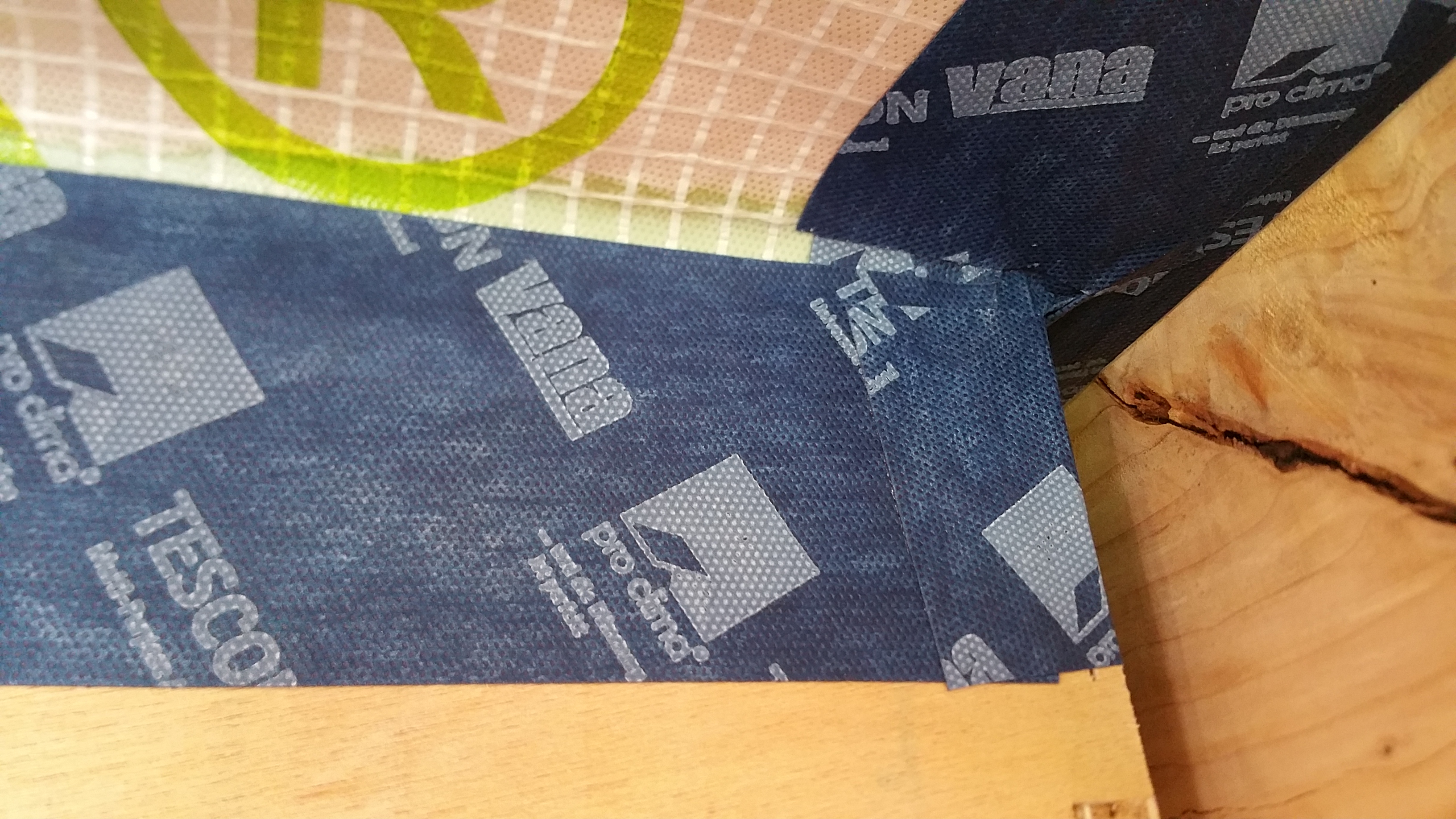
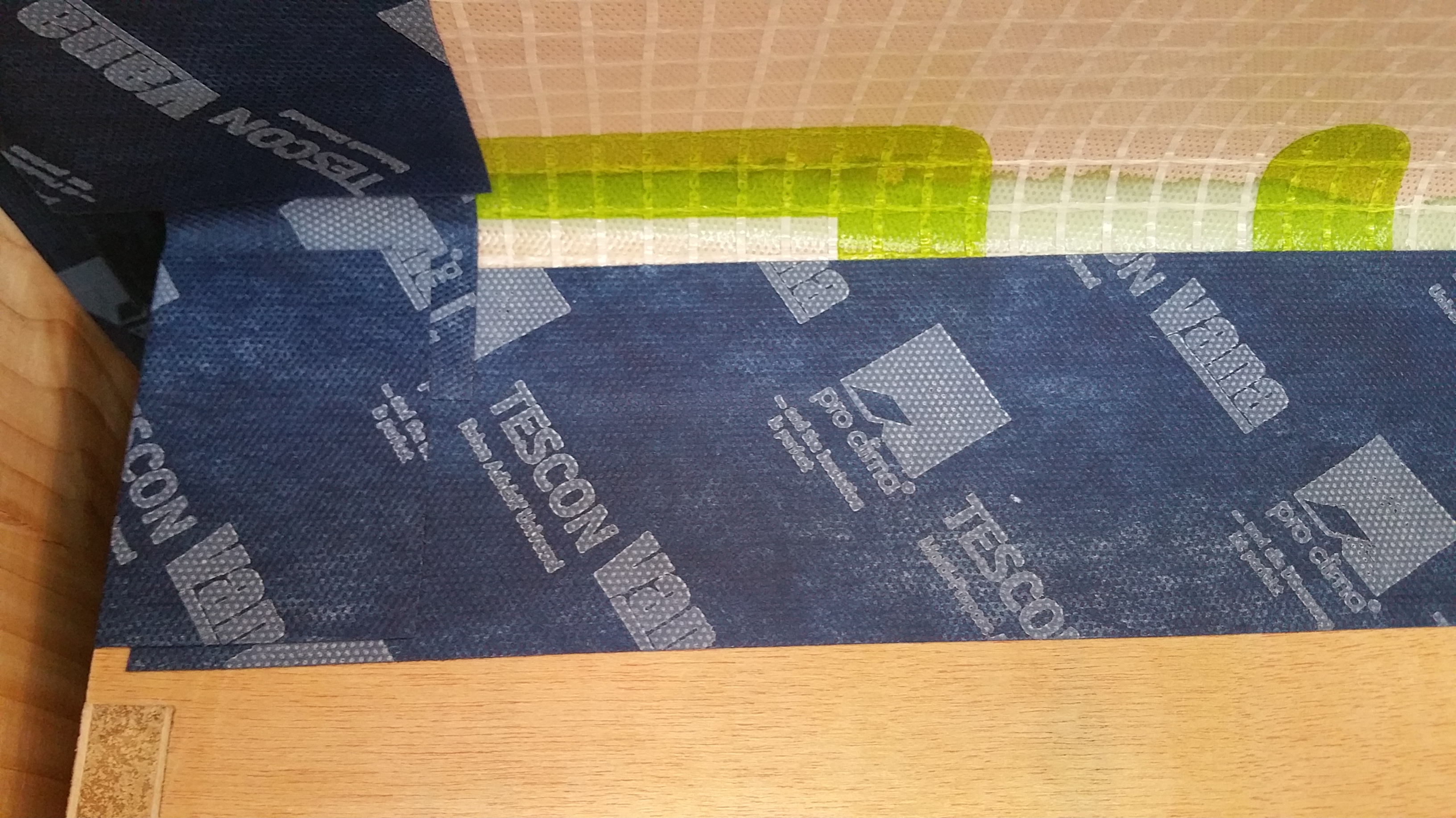

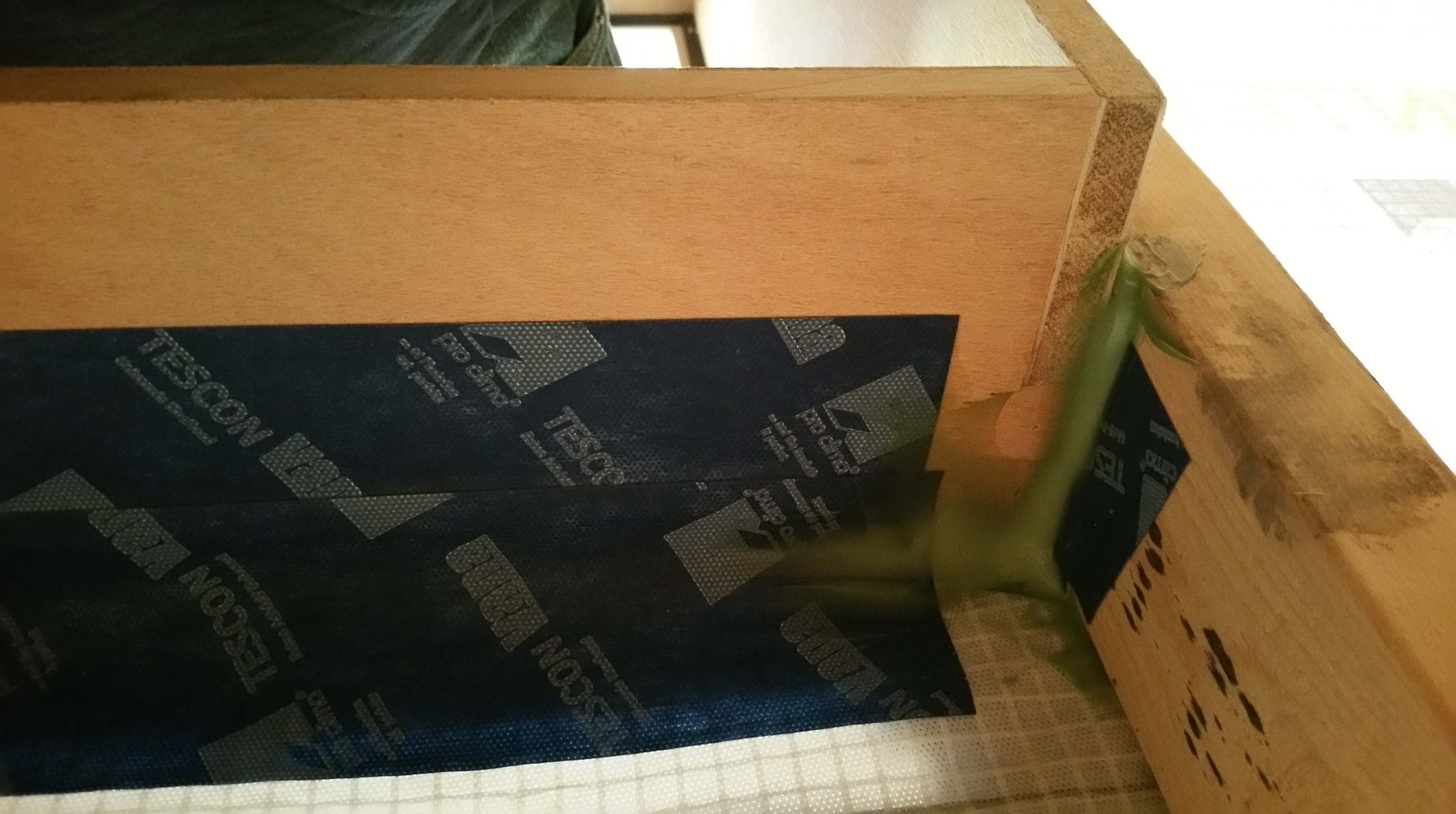
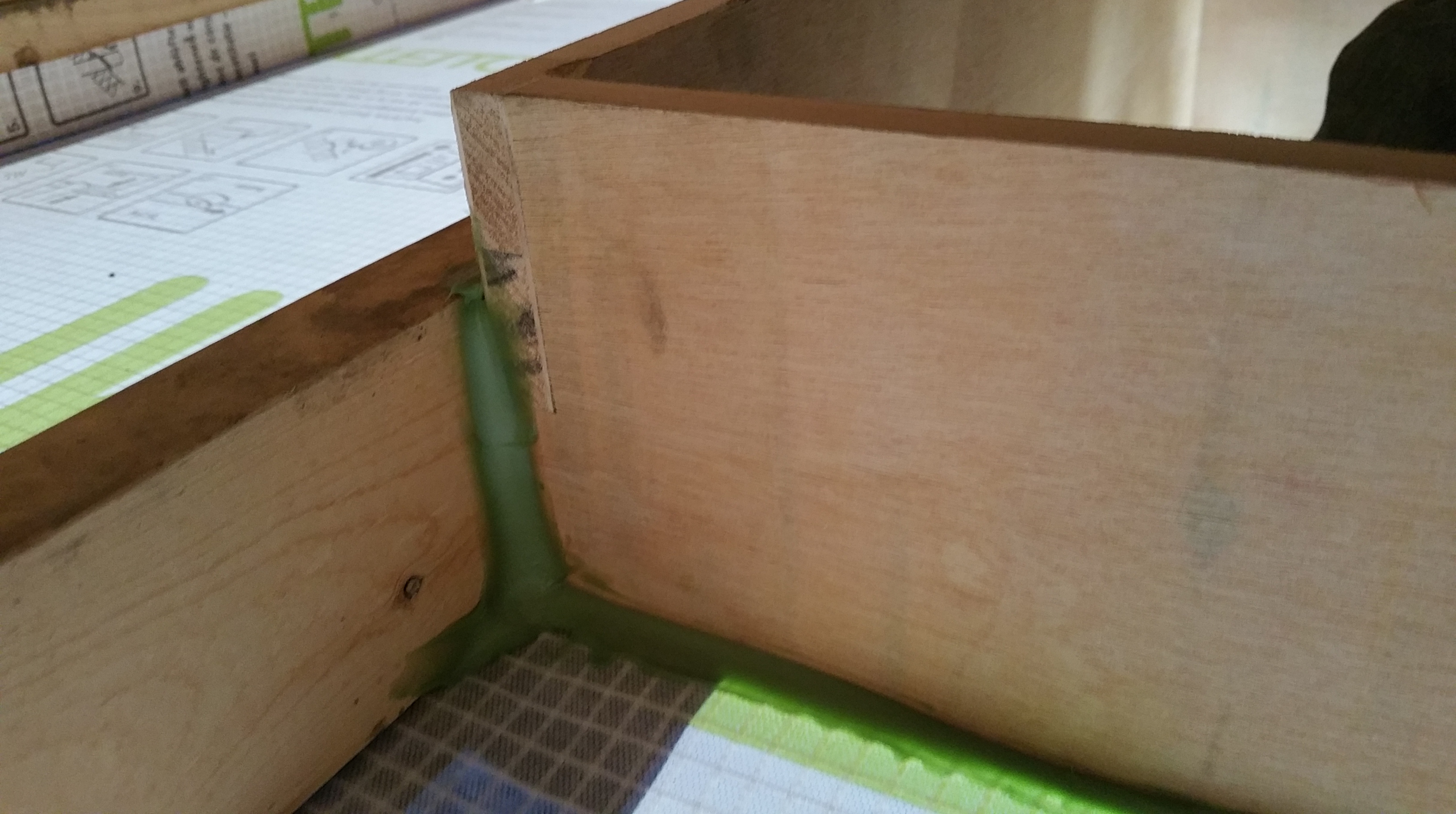
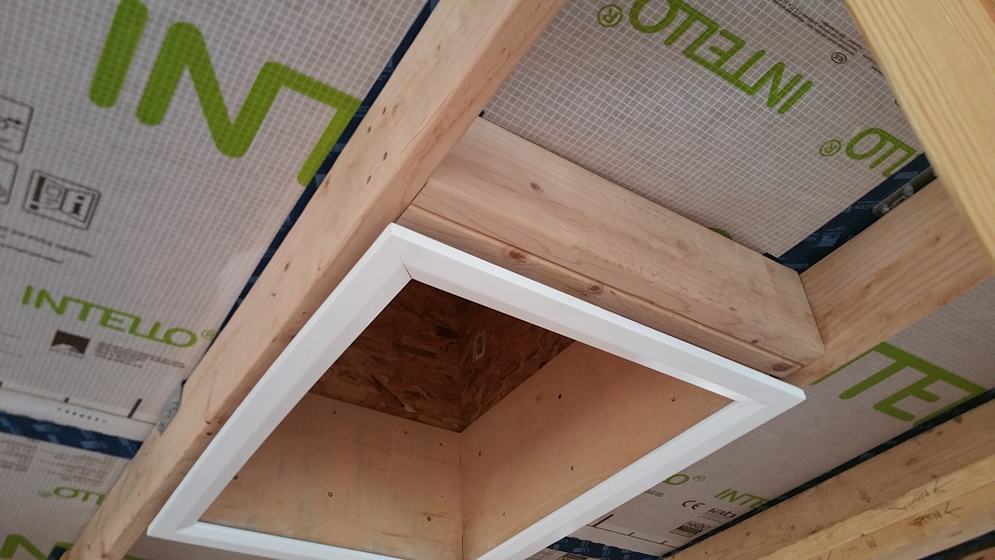
")


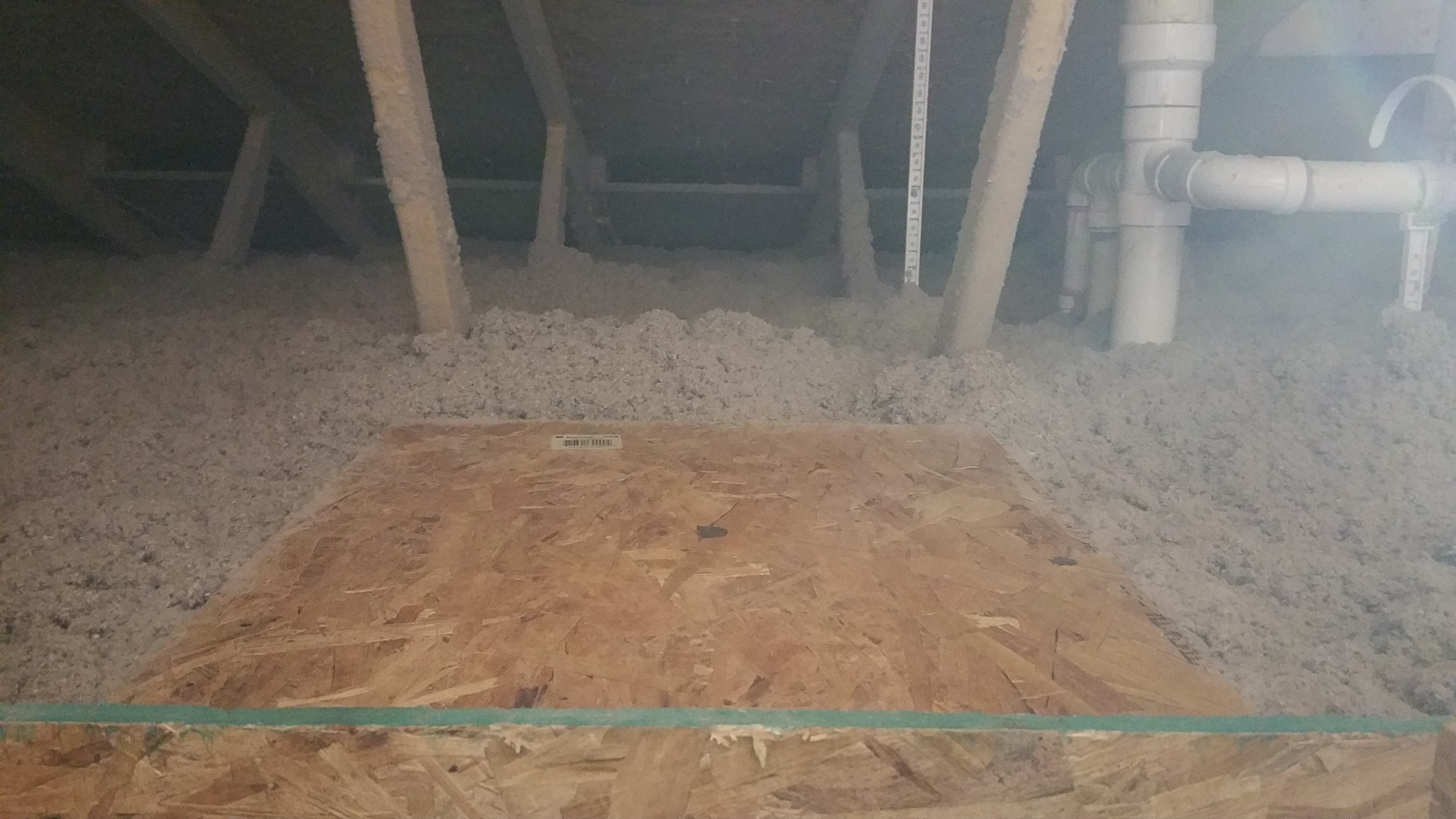

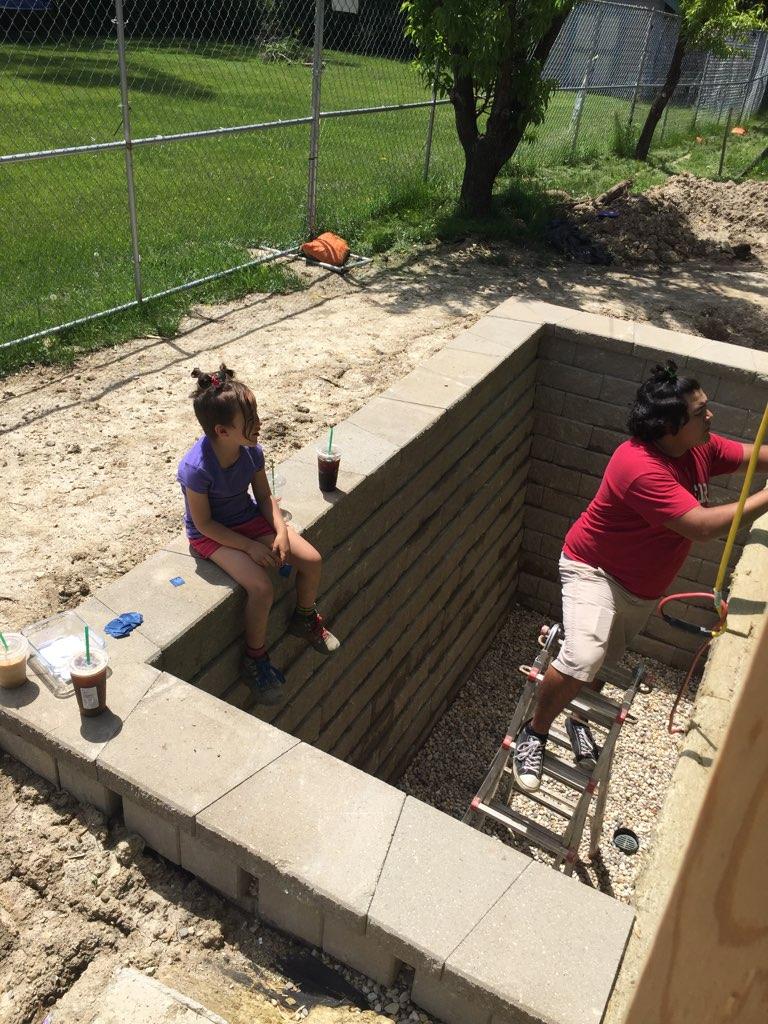


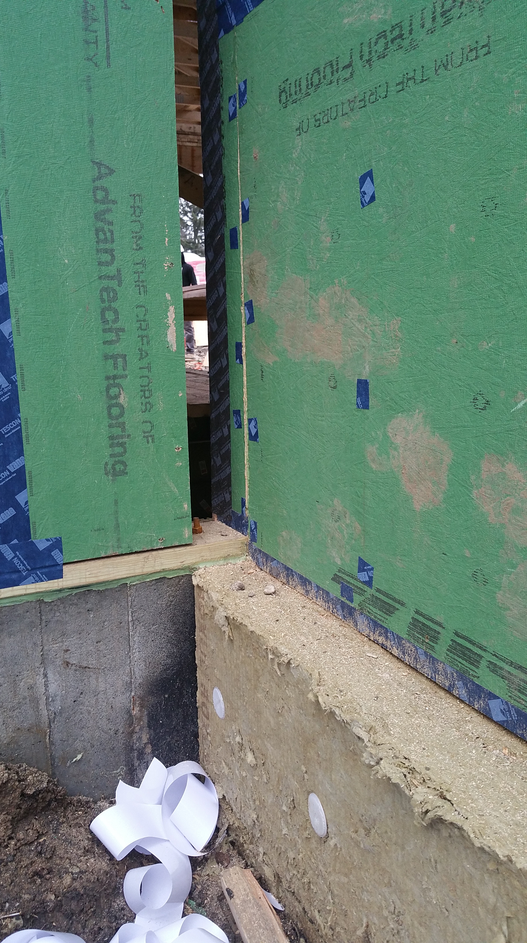
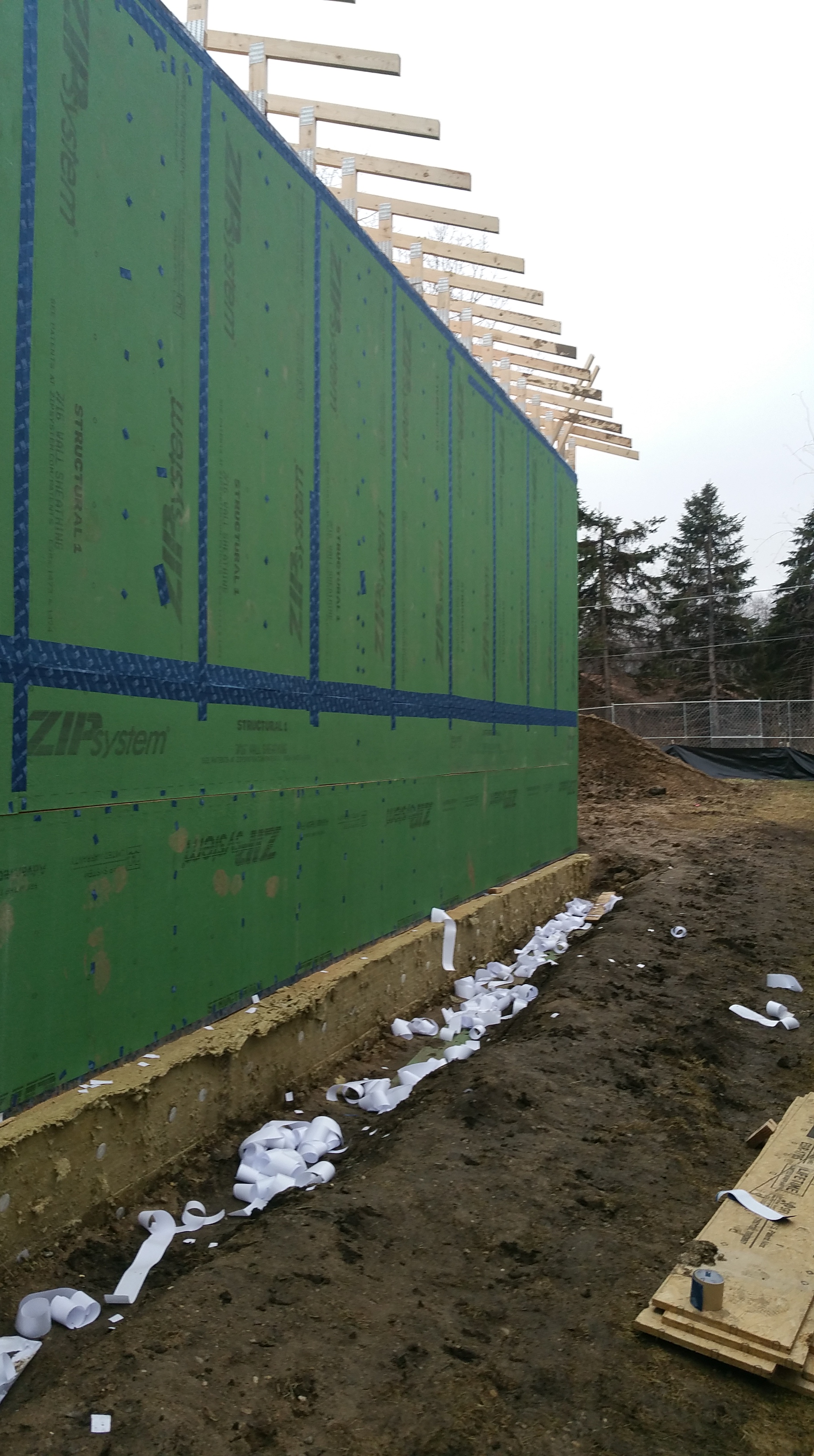

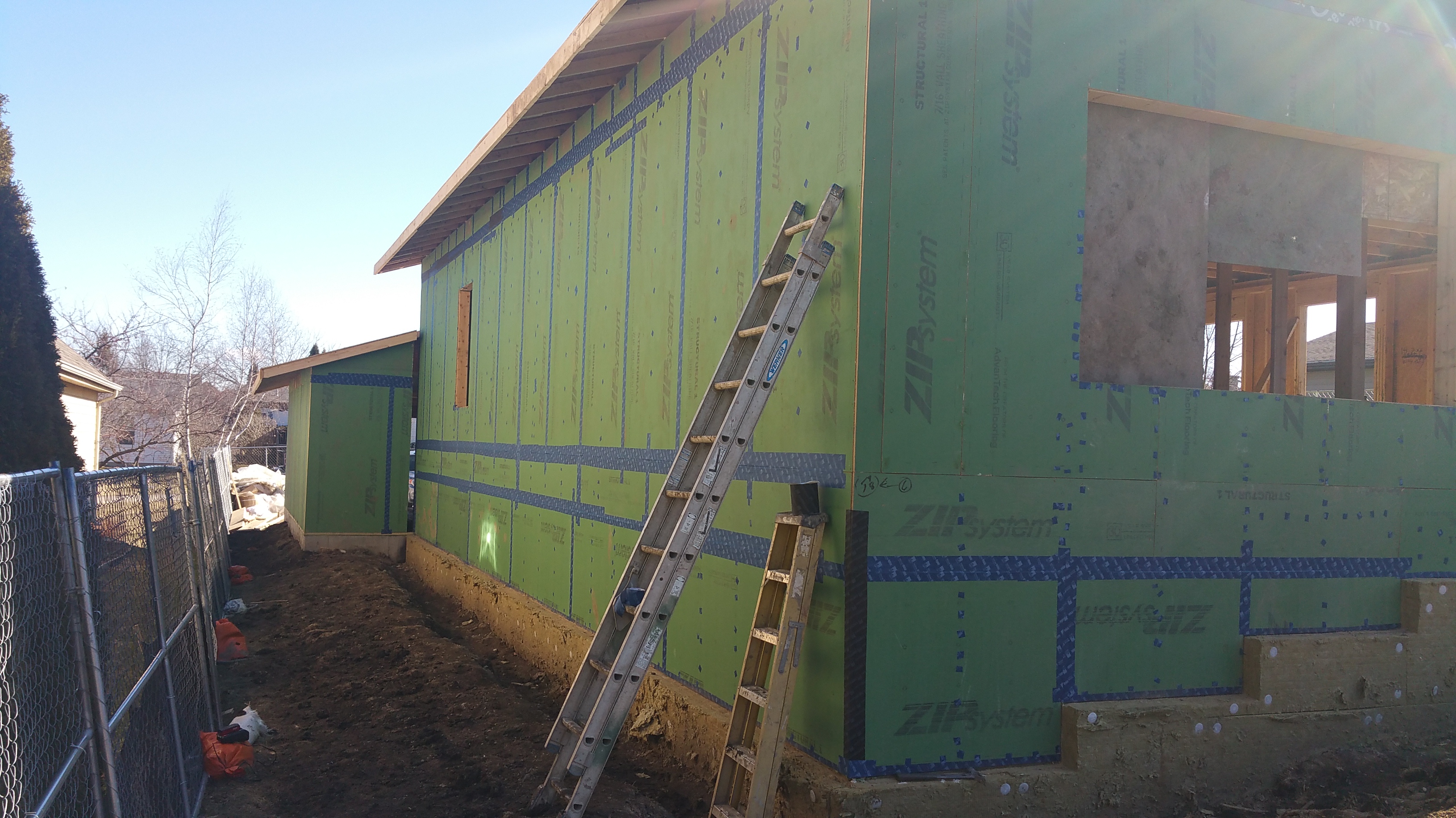
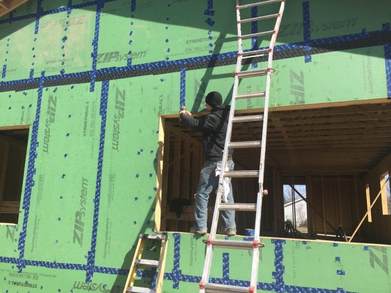
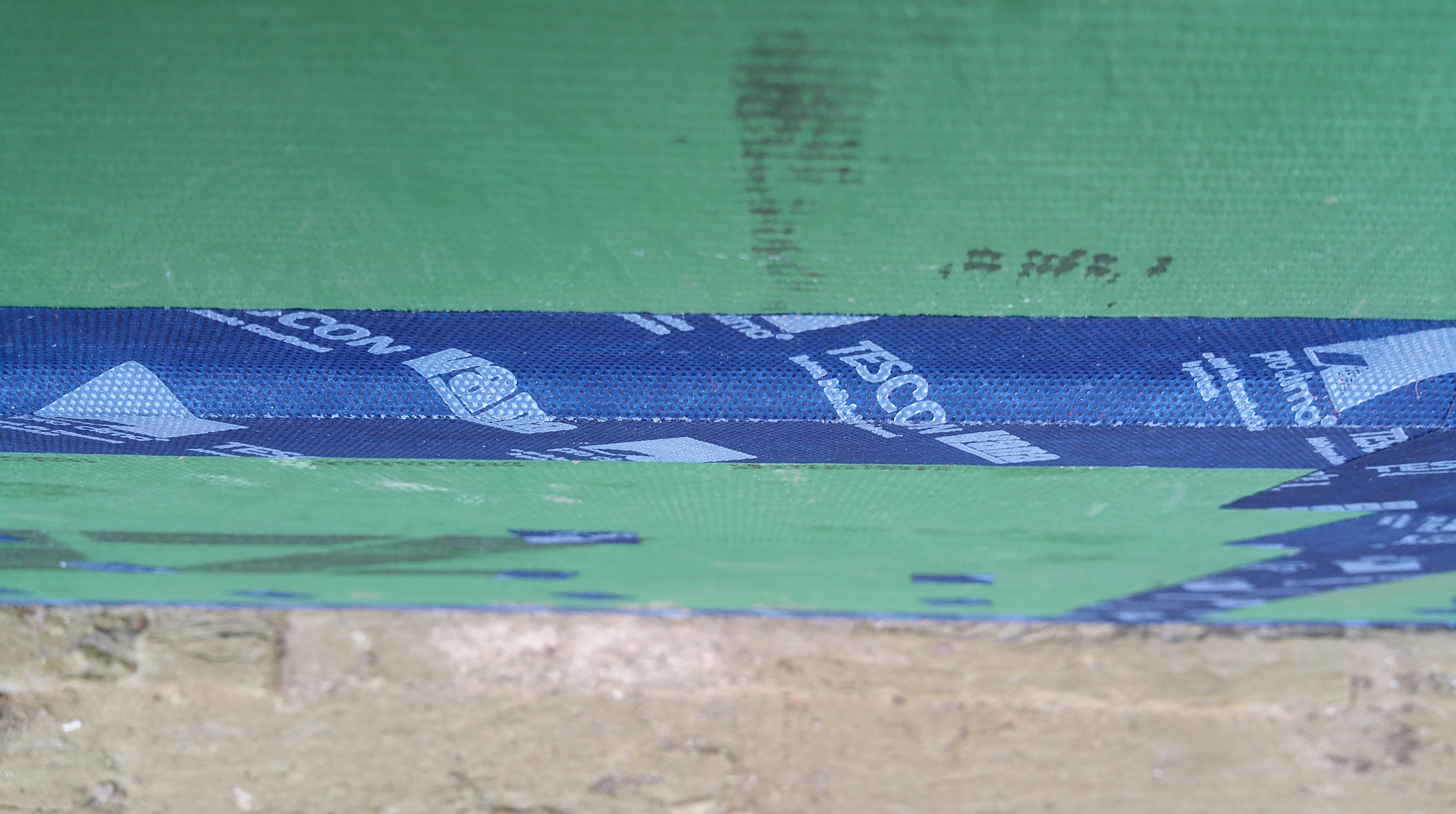
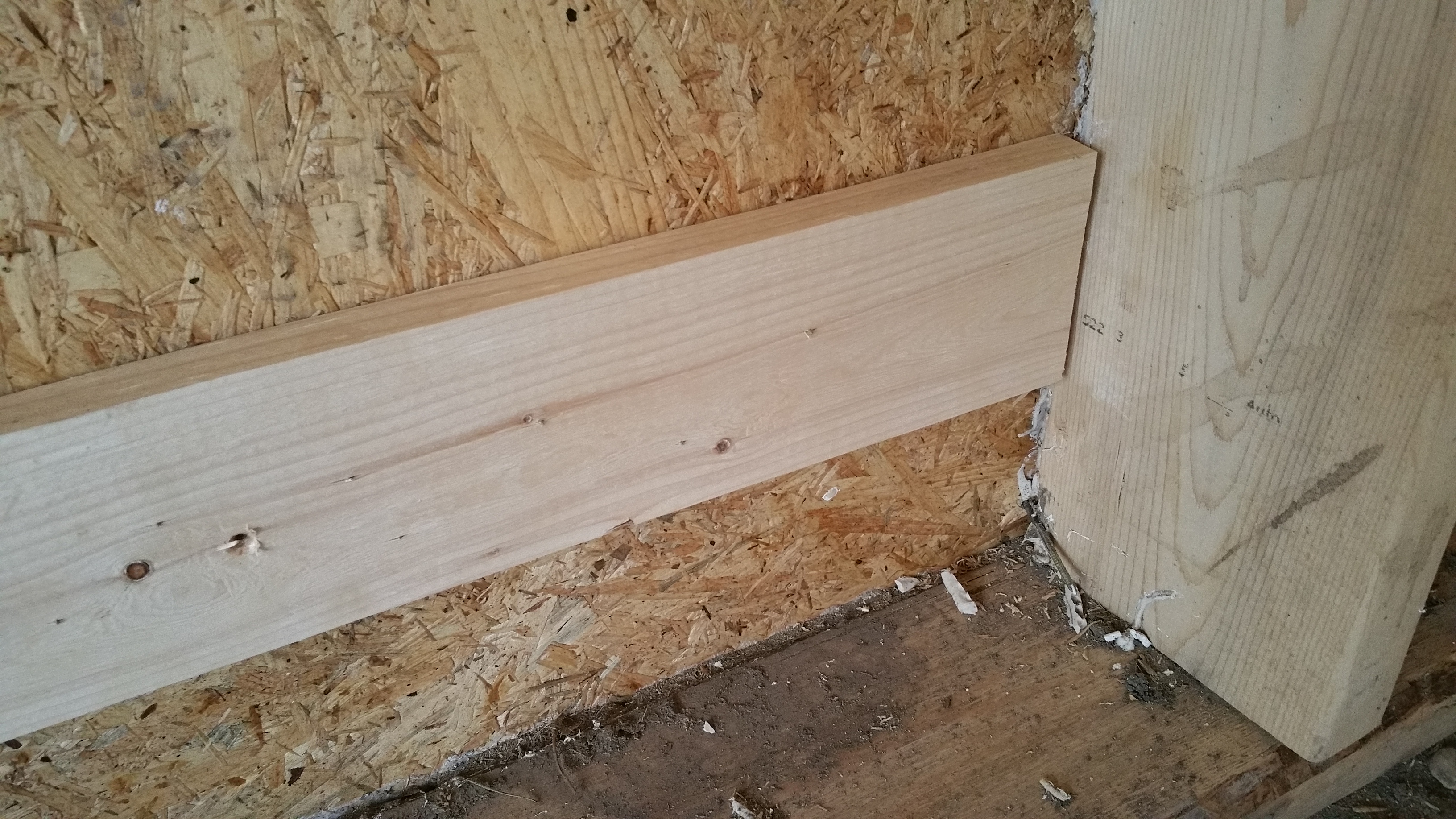
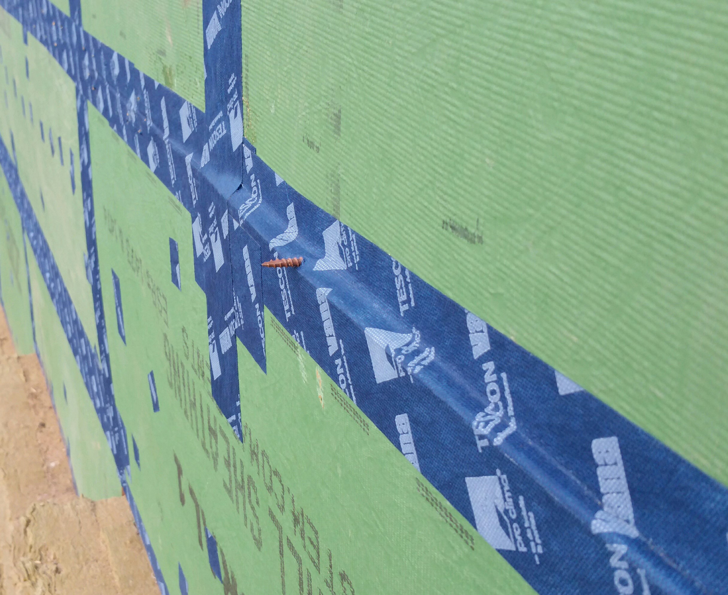
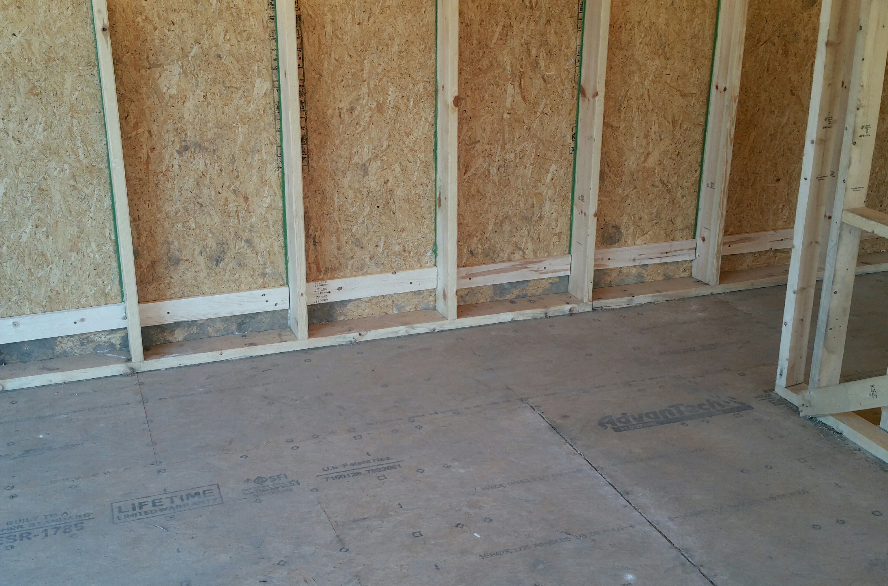
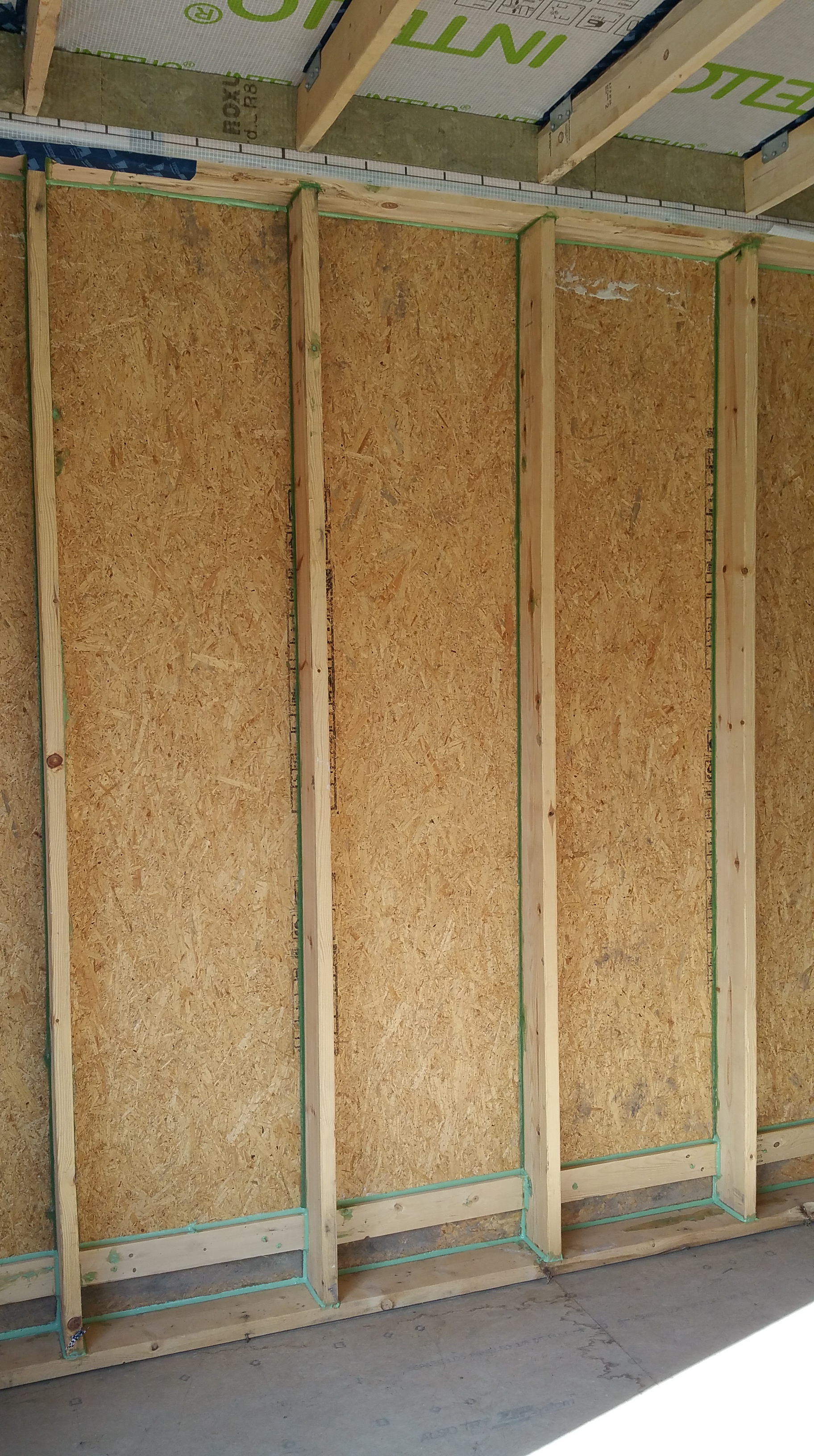

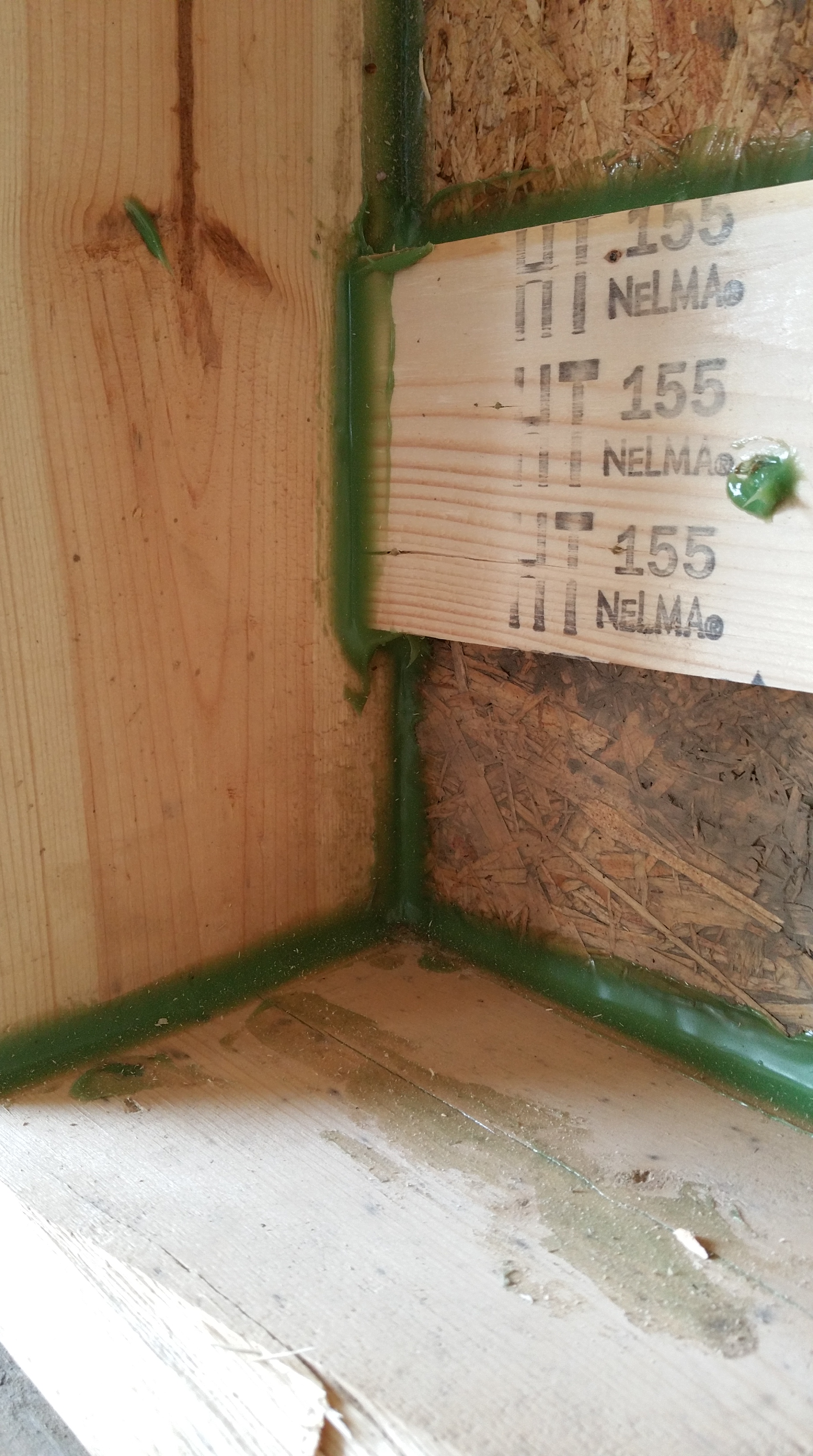
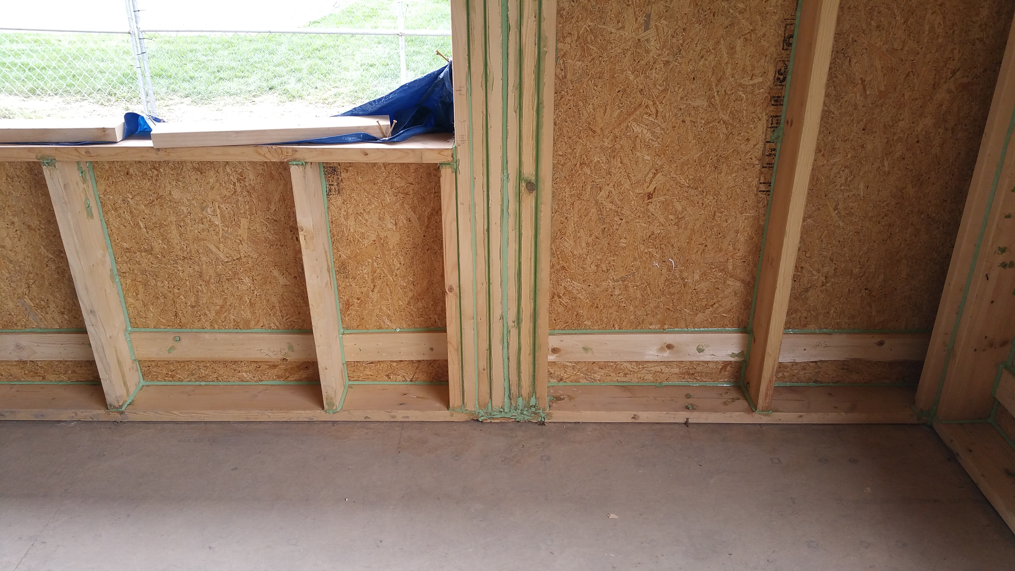

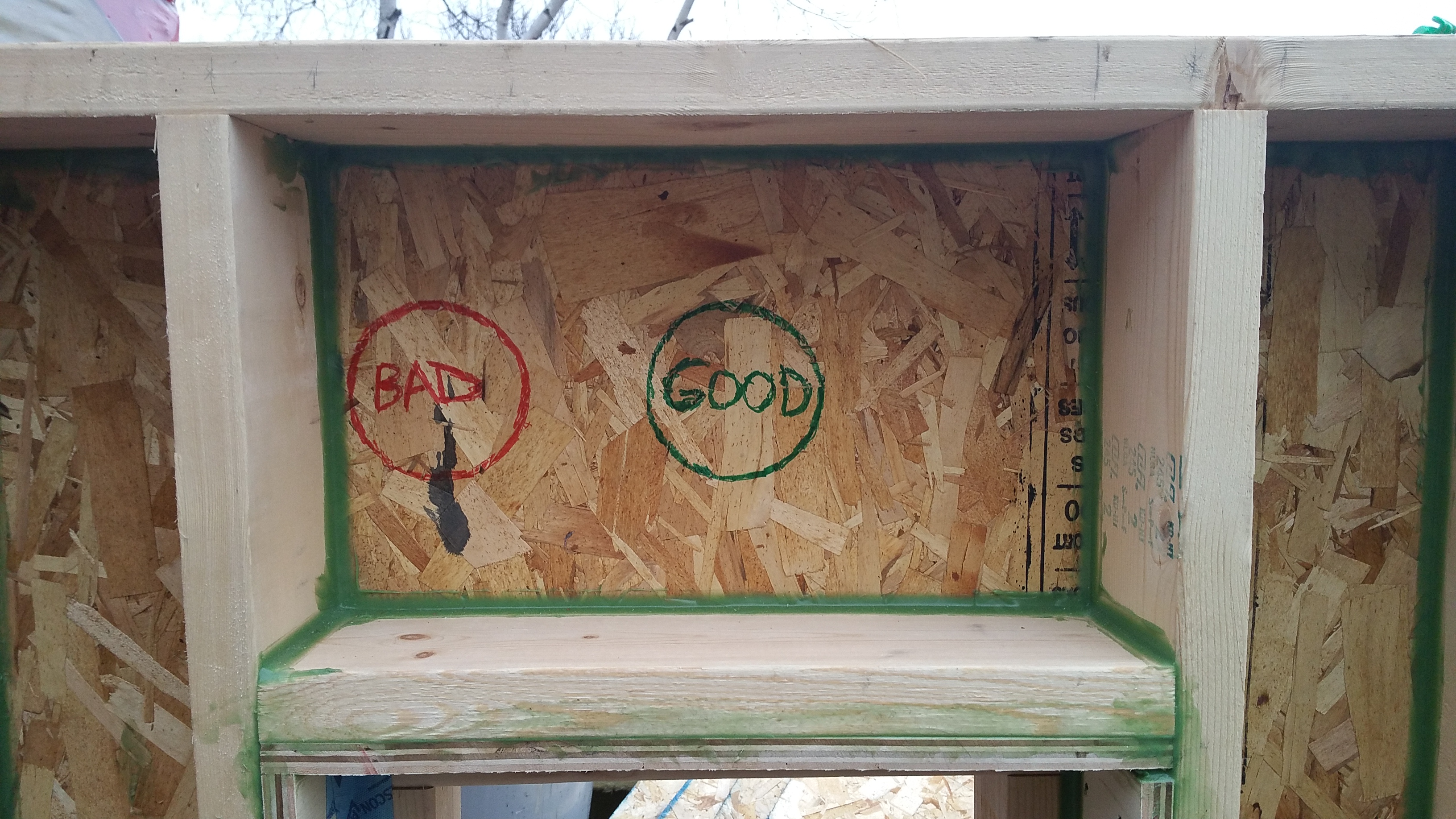
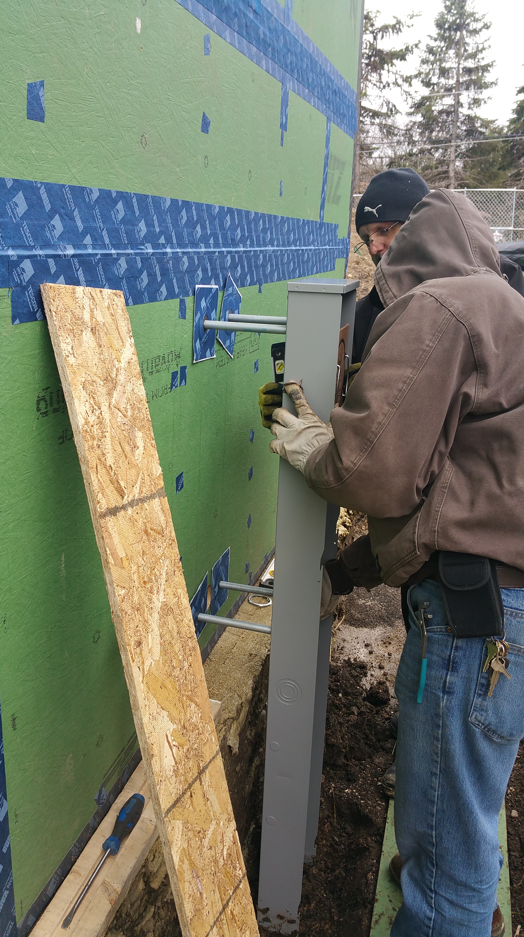
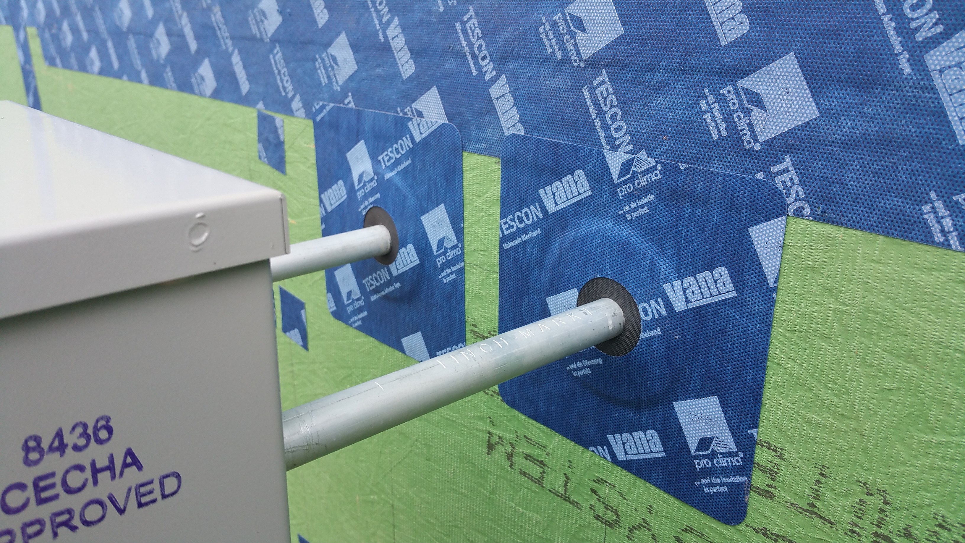
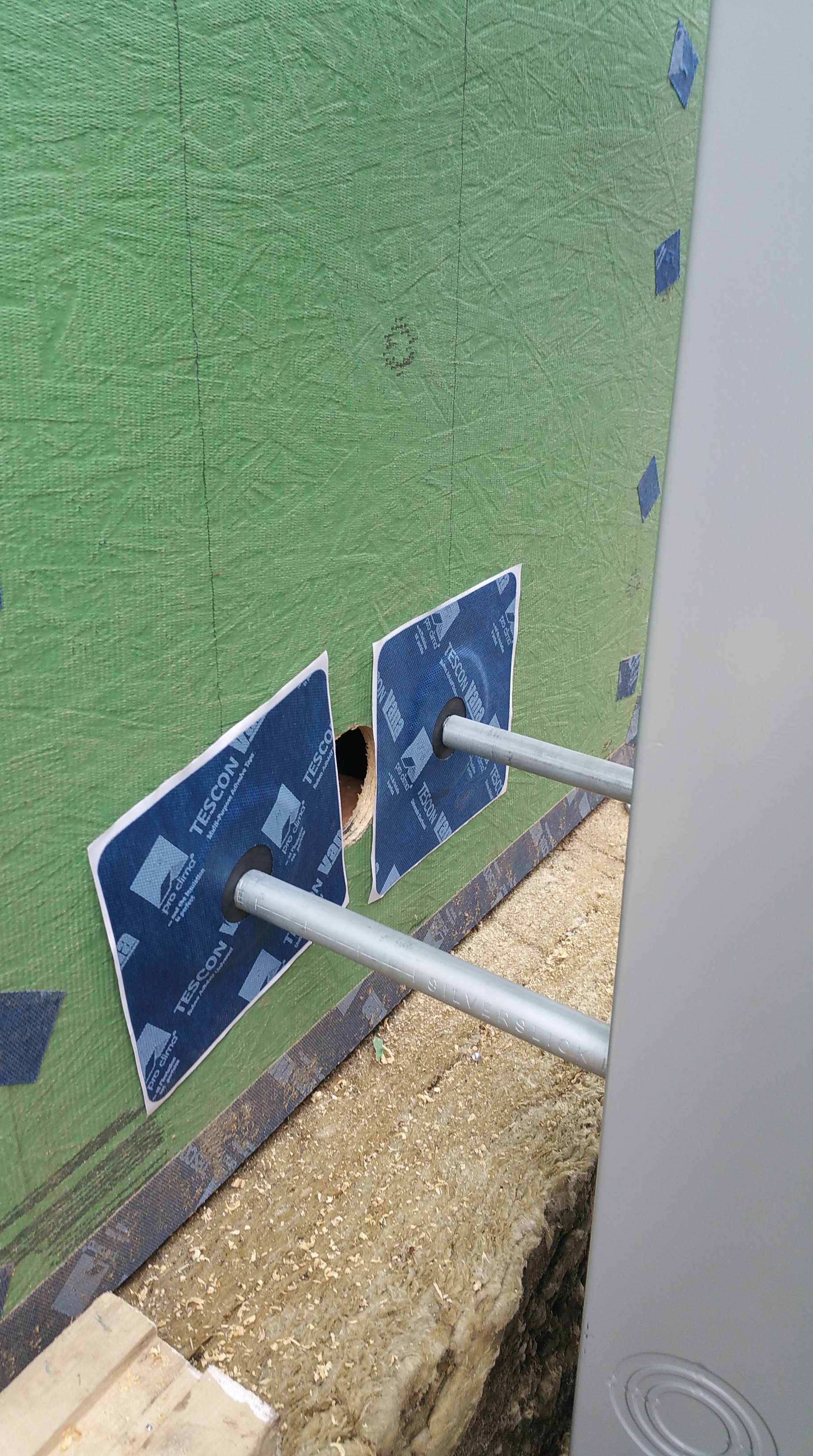
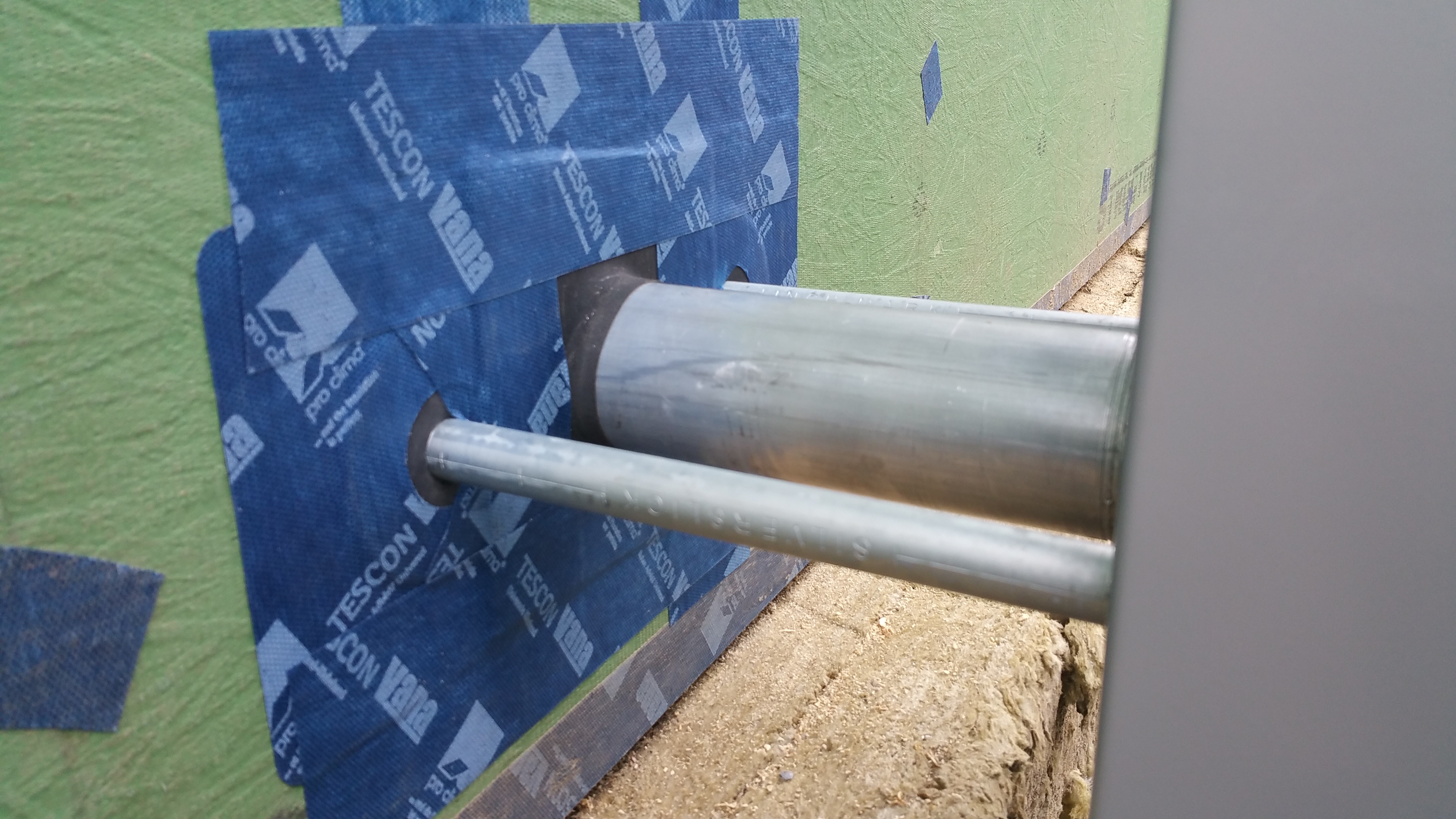
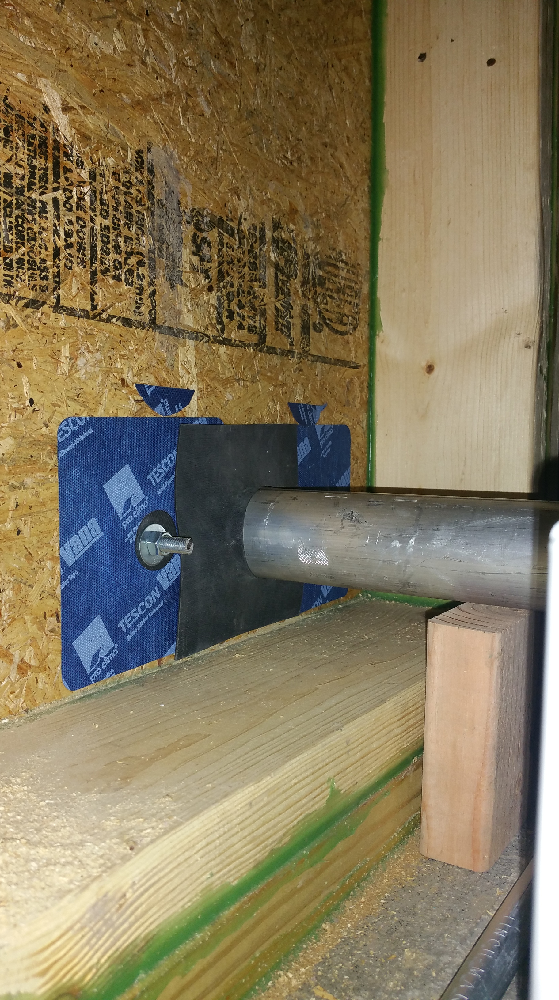
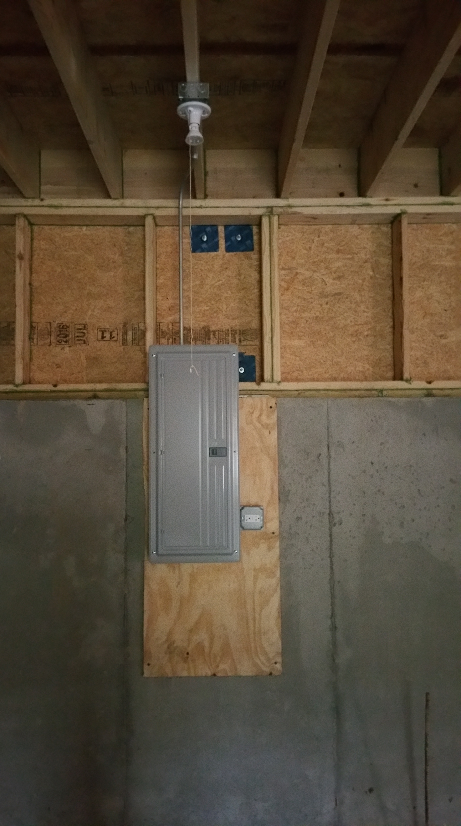


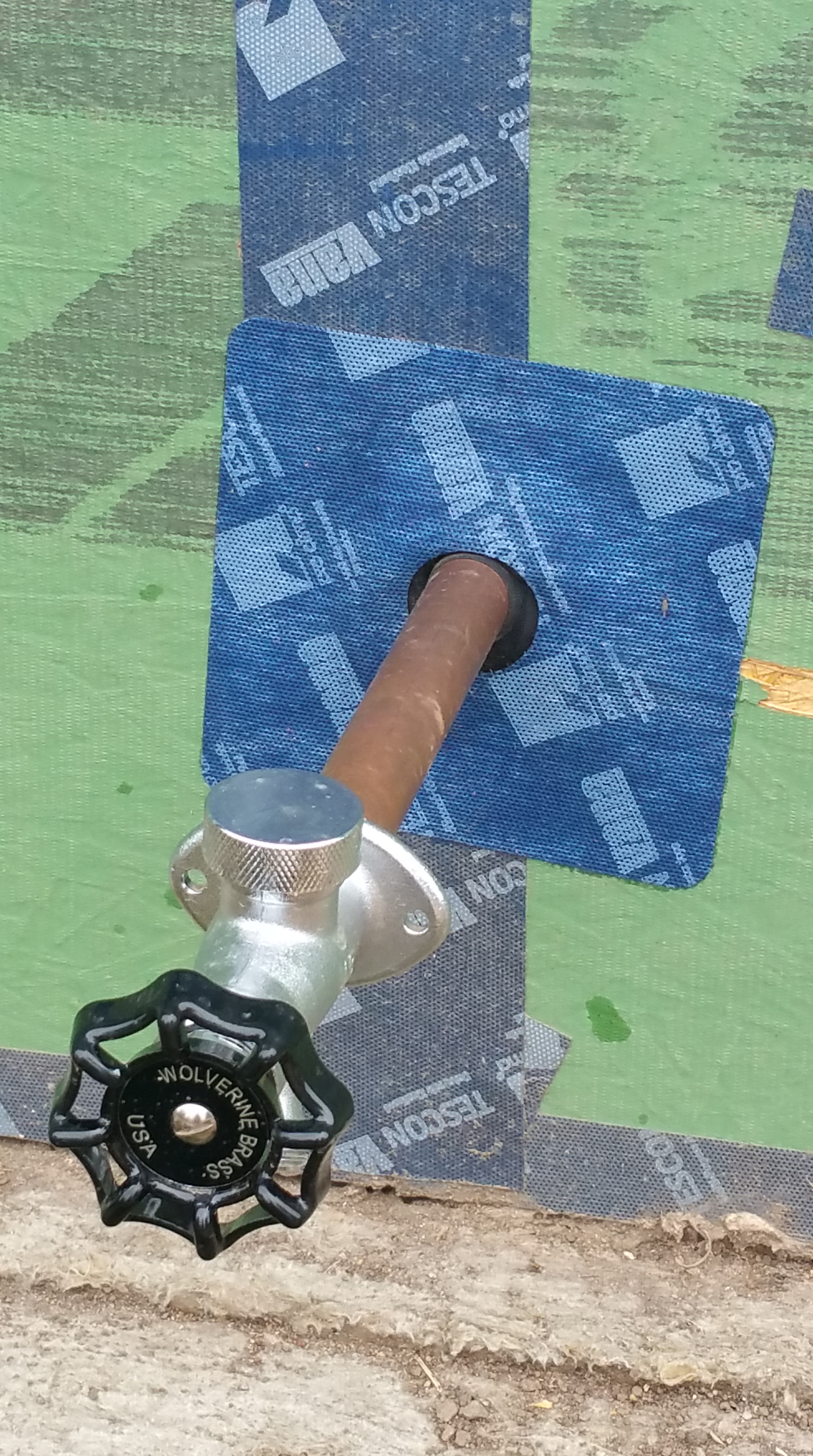
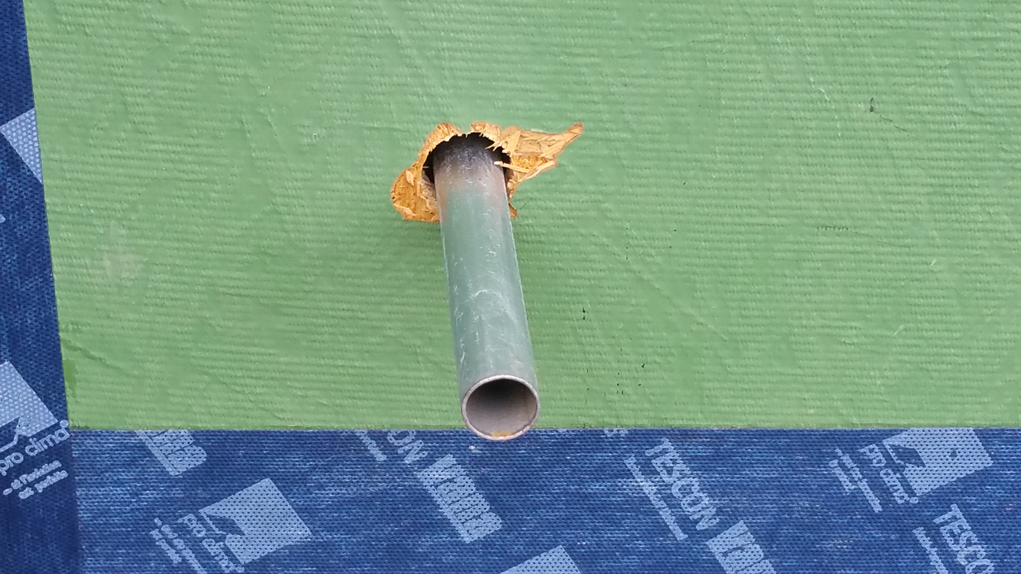

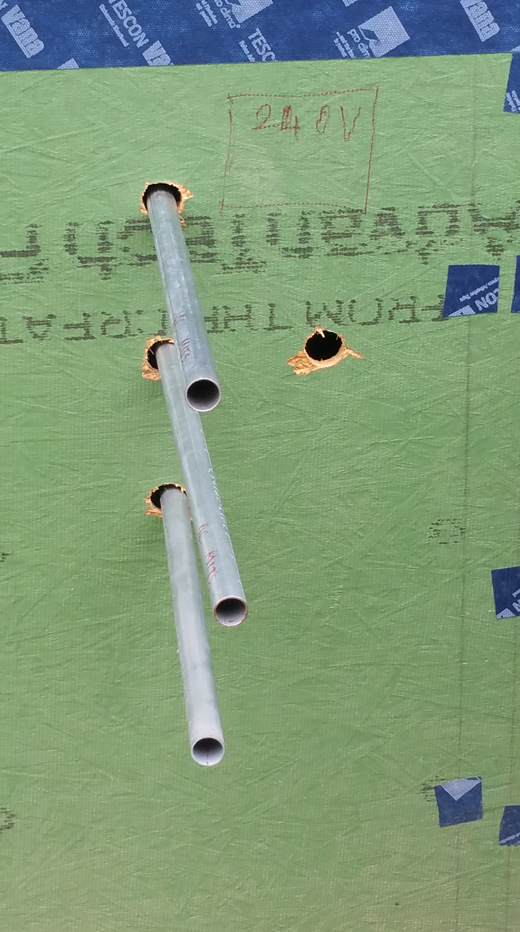


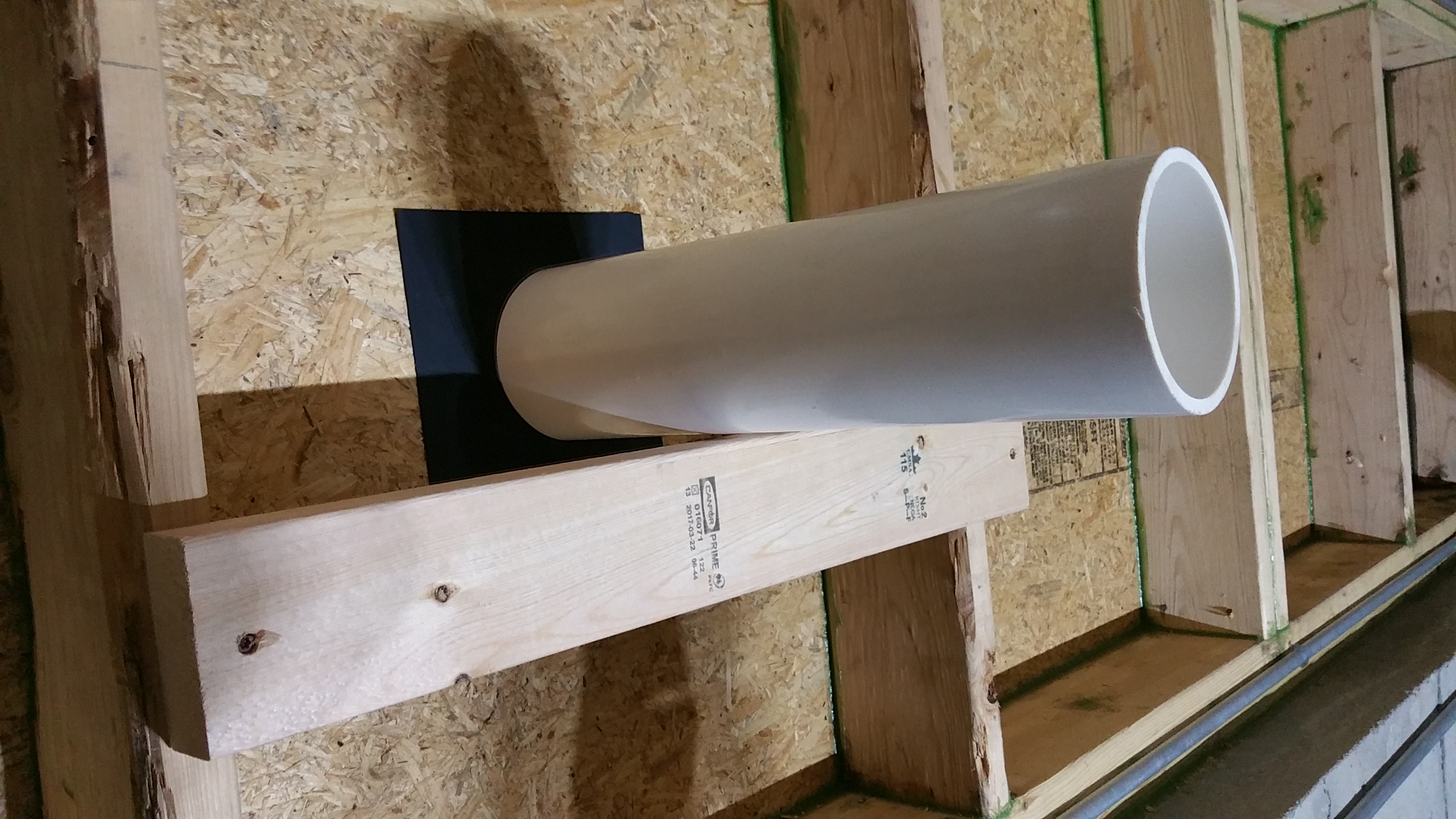


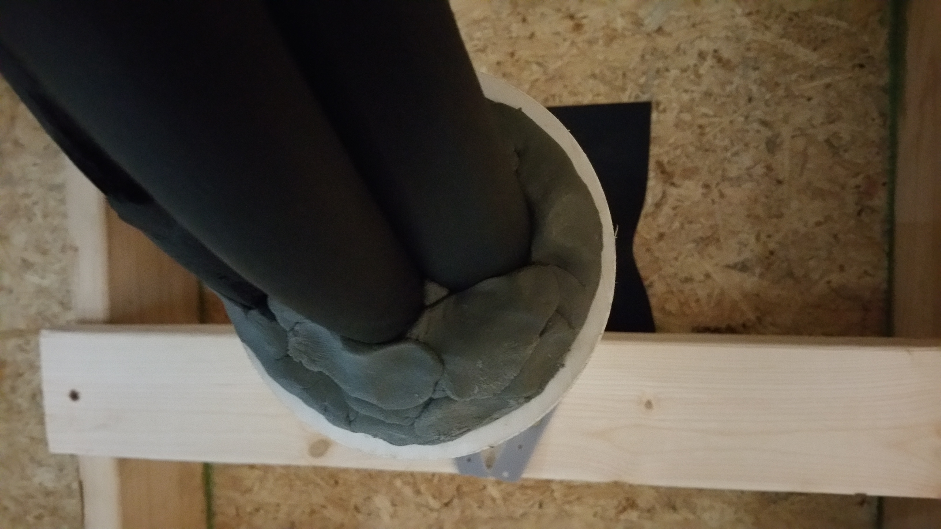
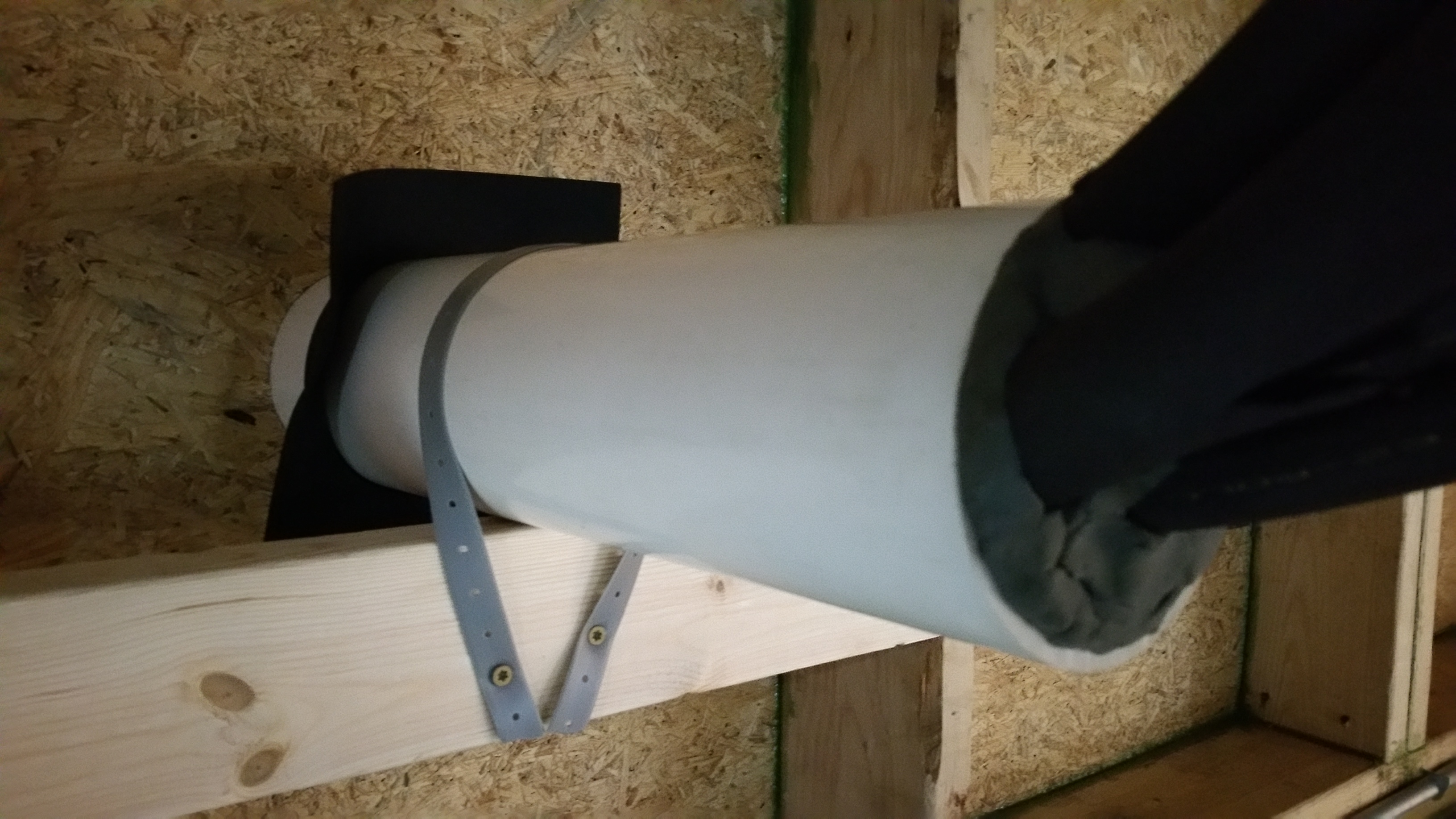
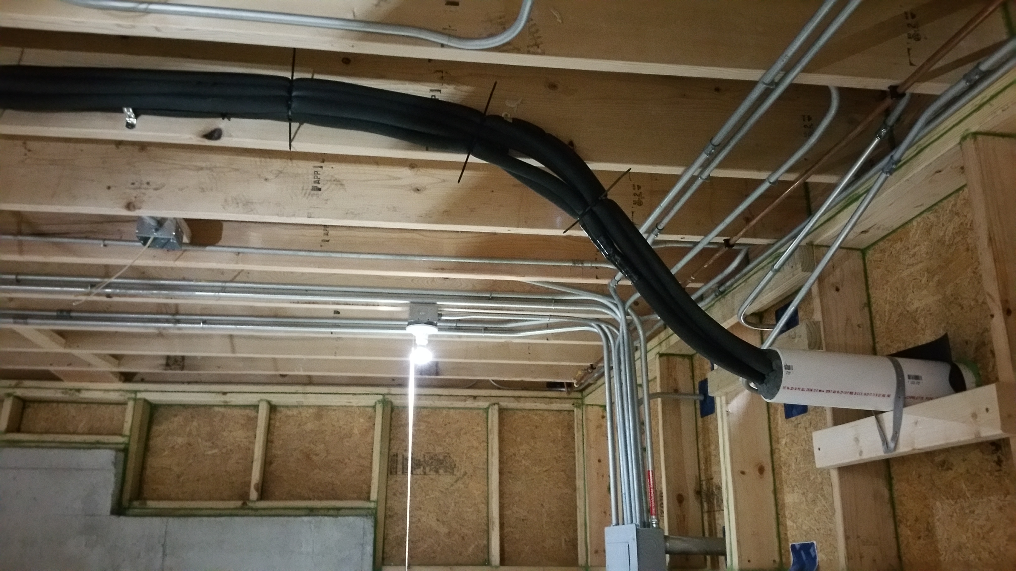
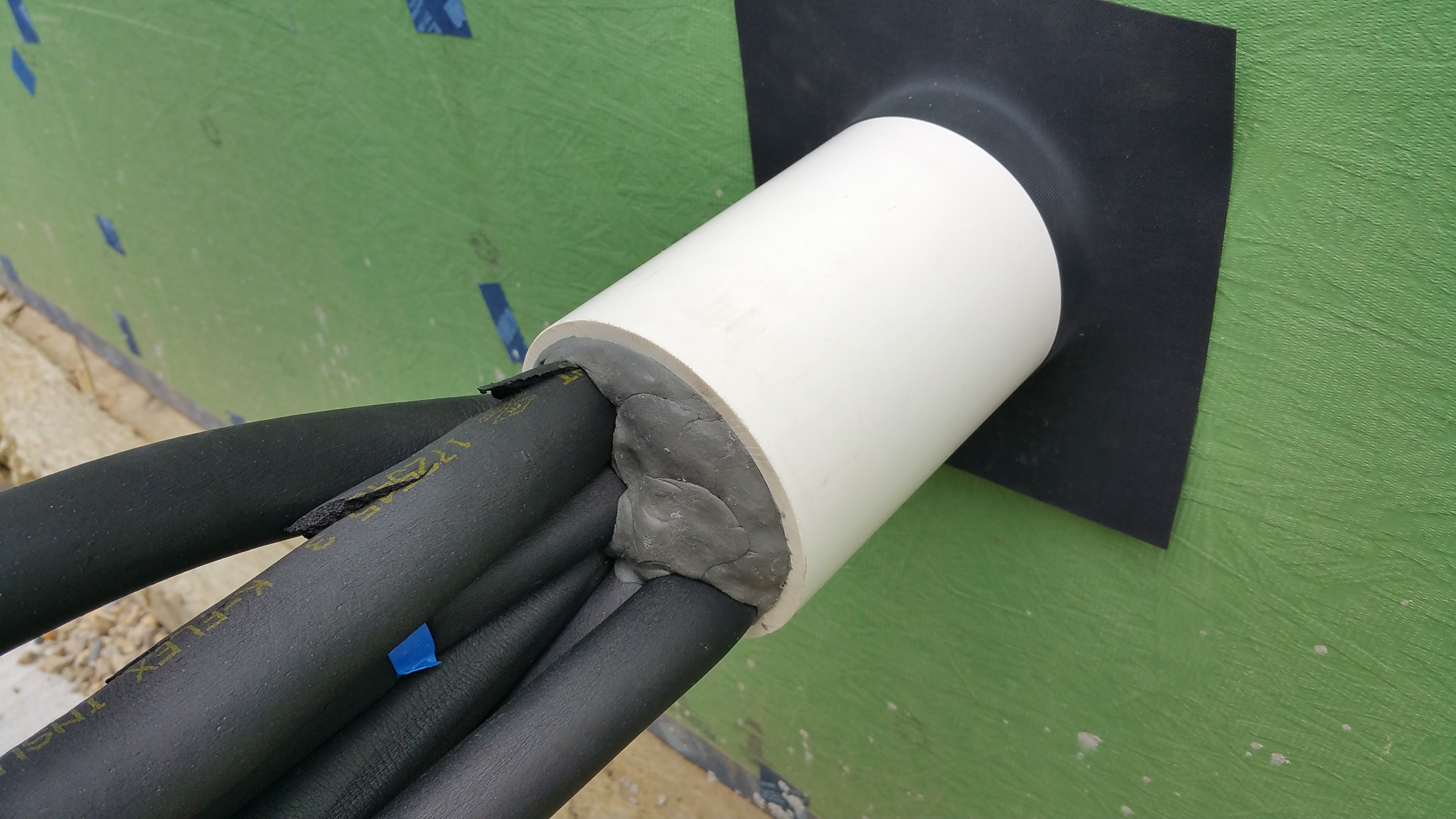
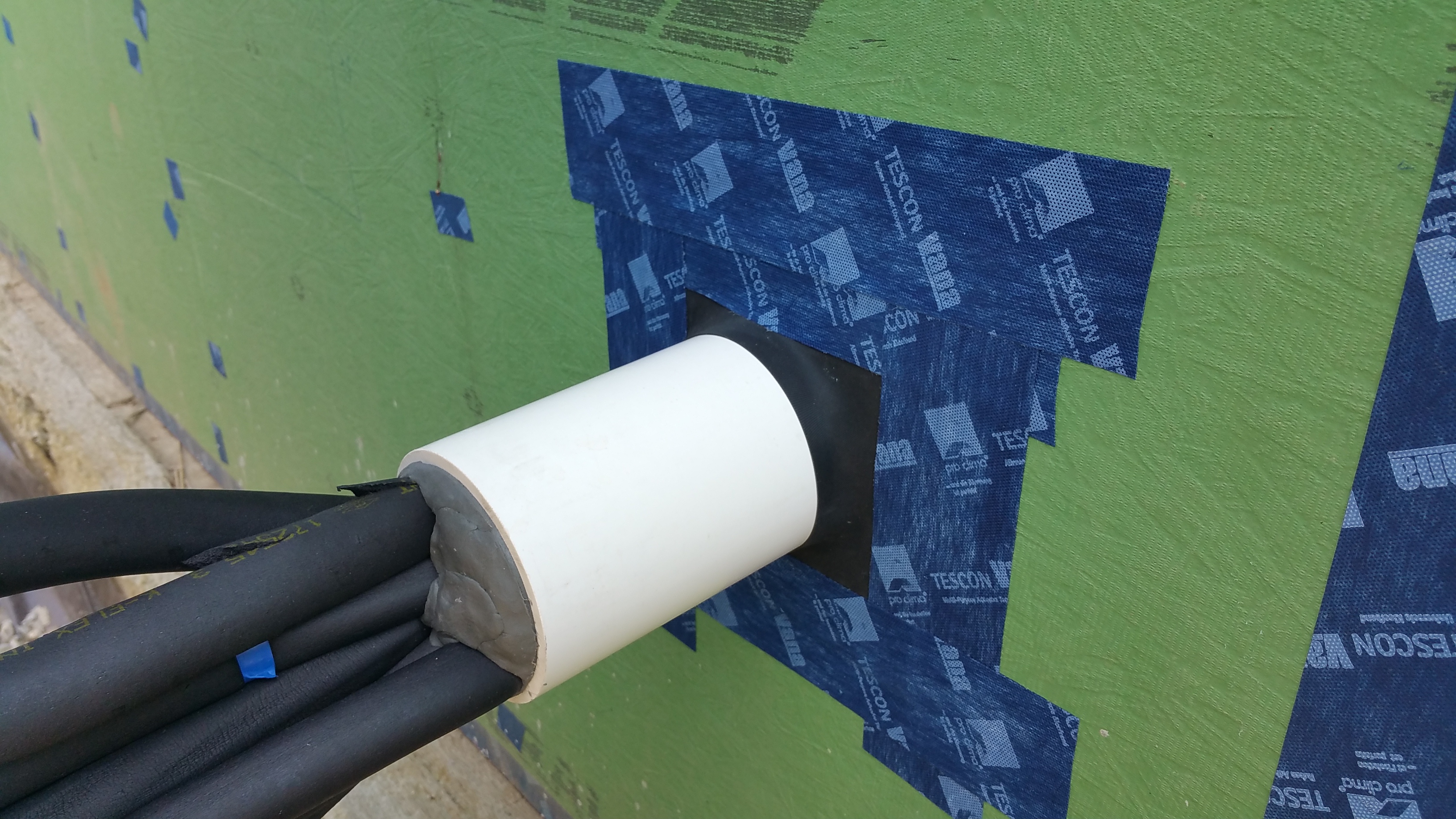
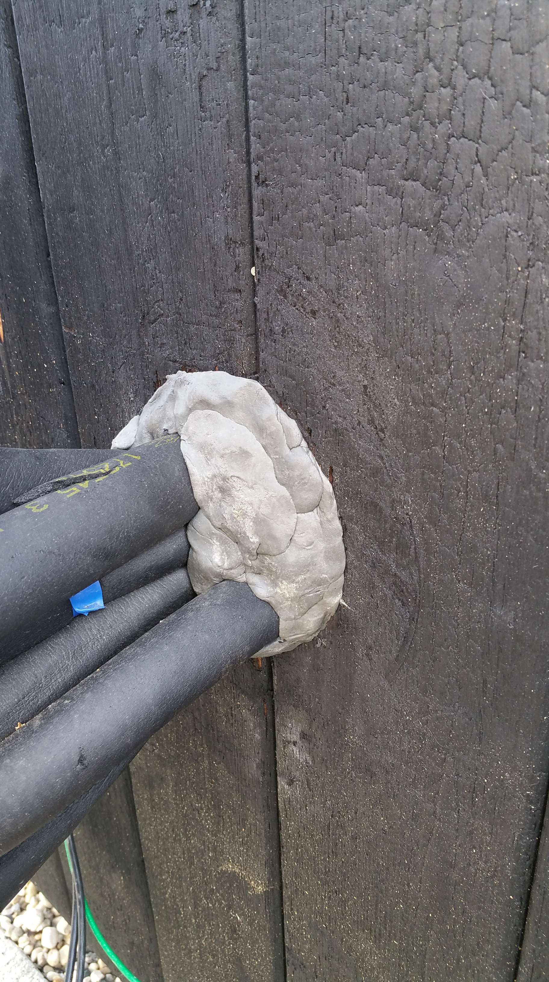
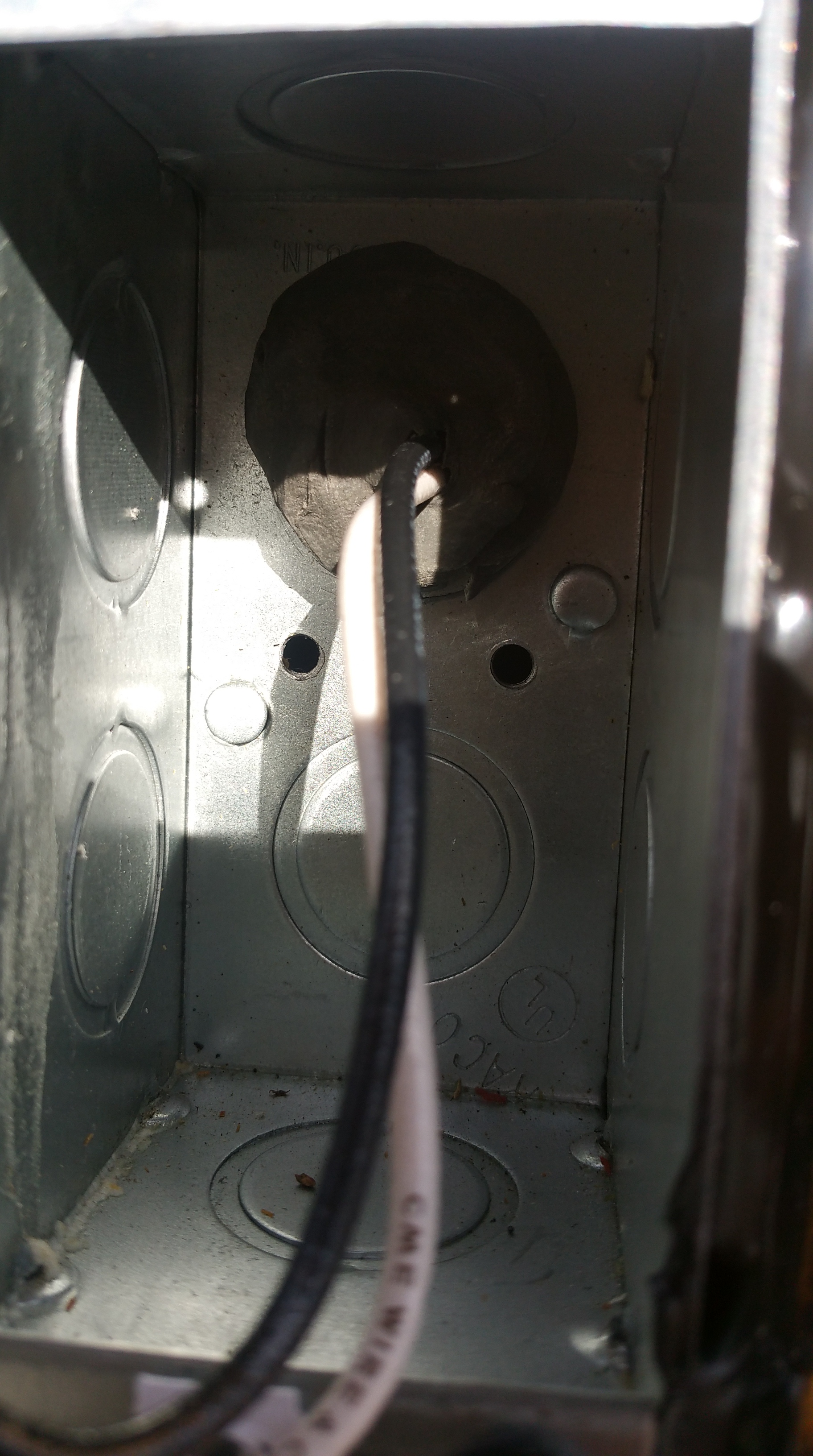


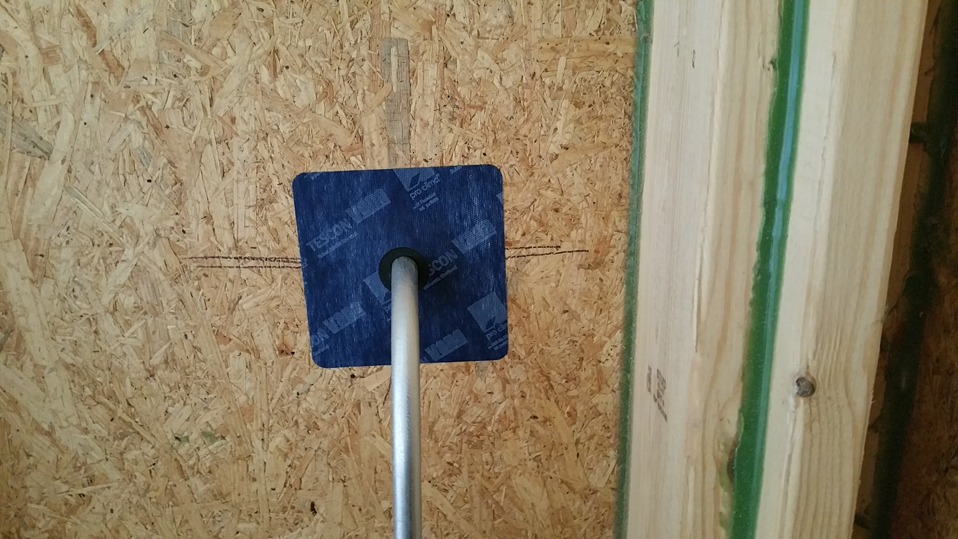


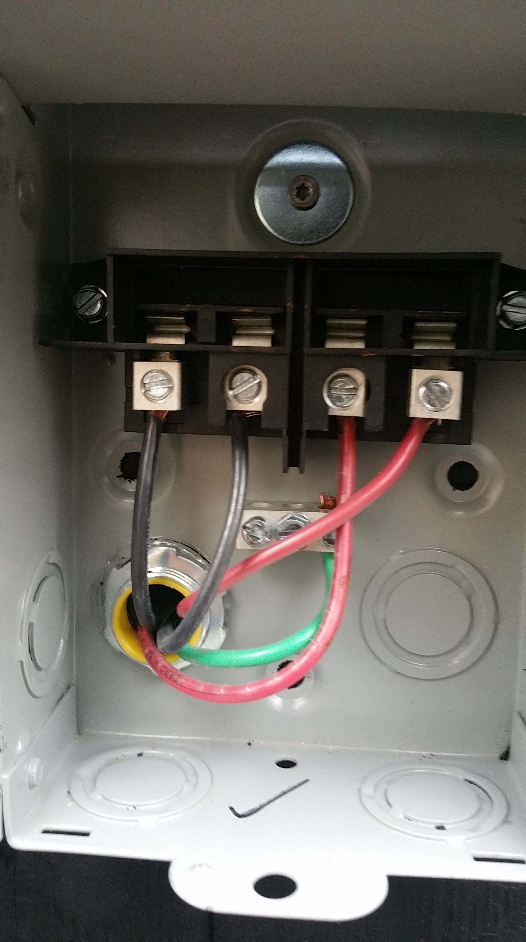

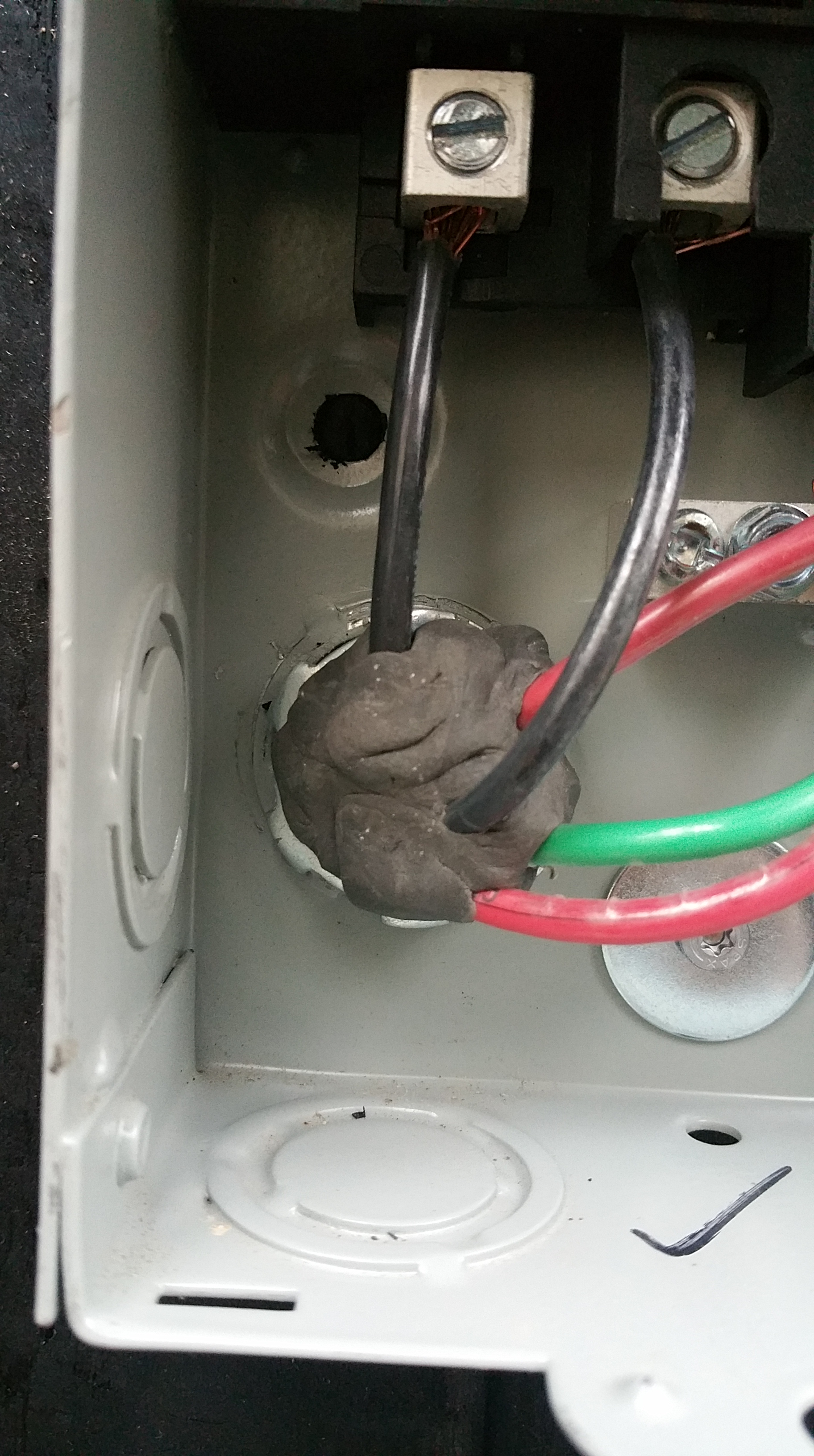


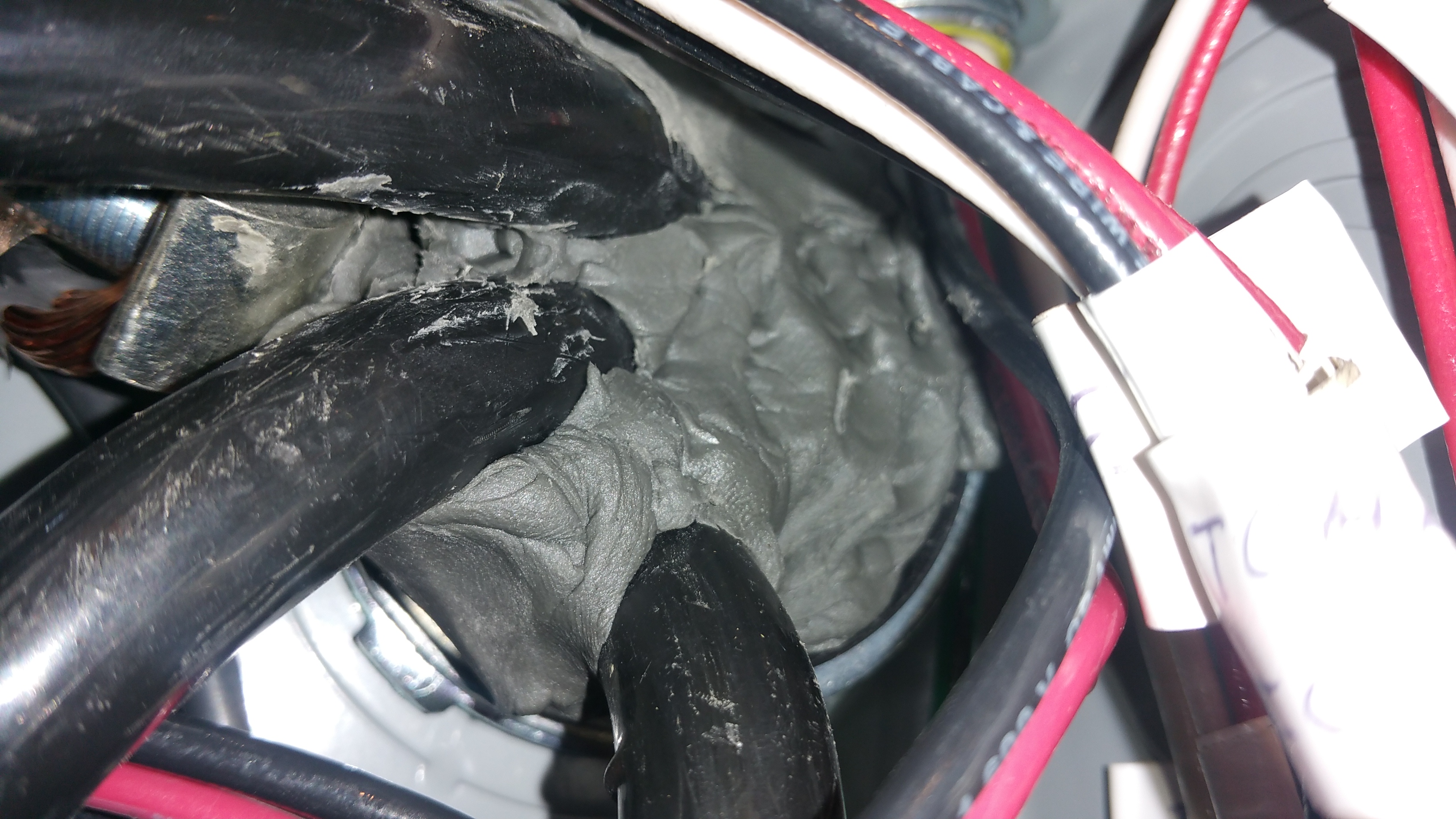
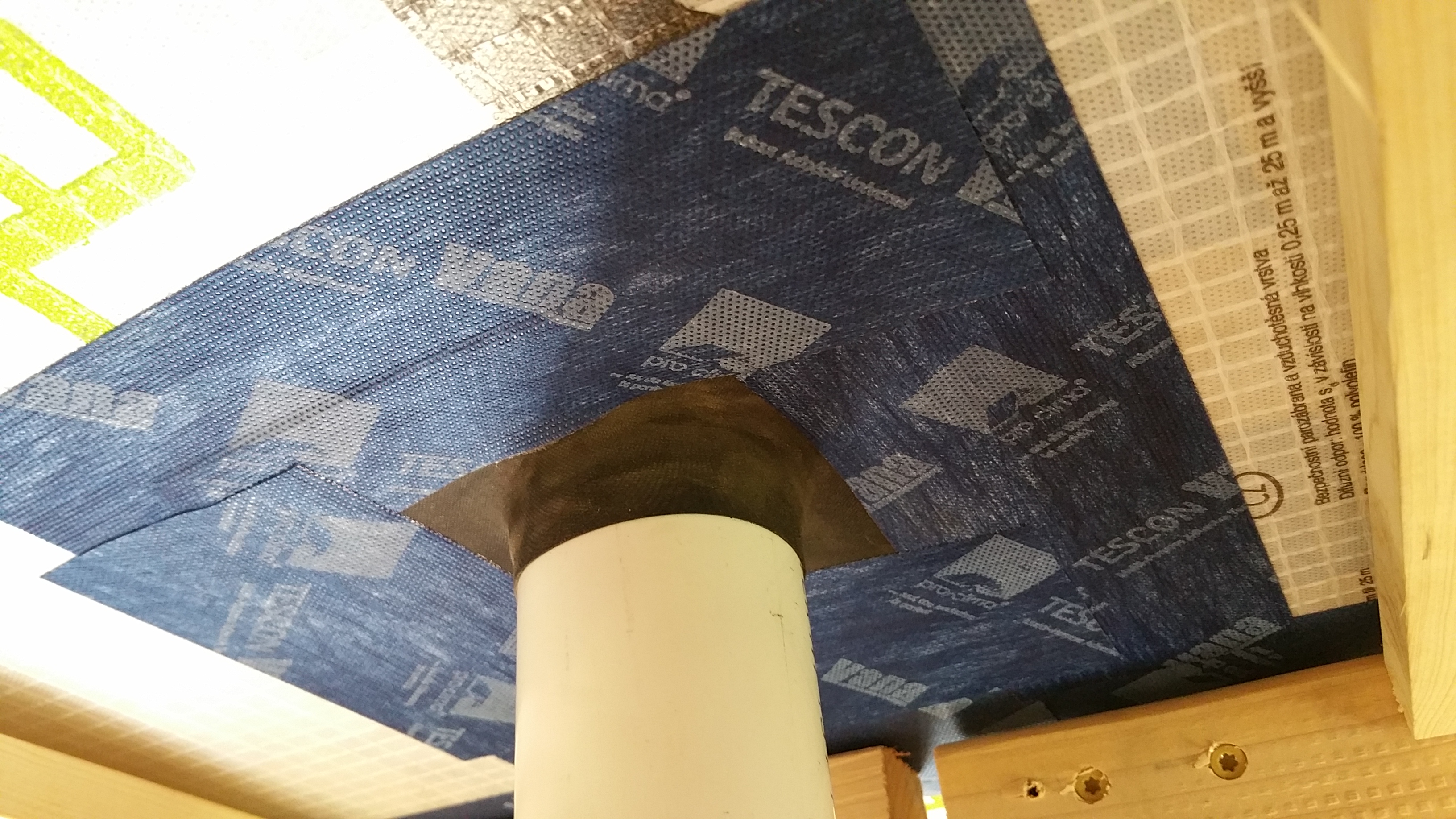

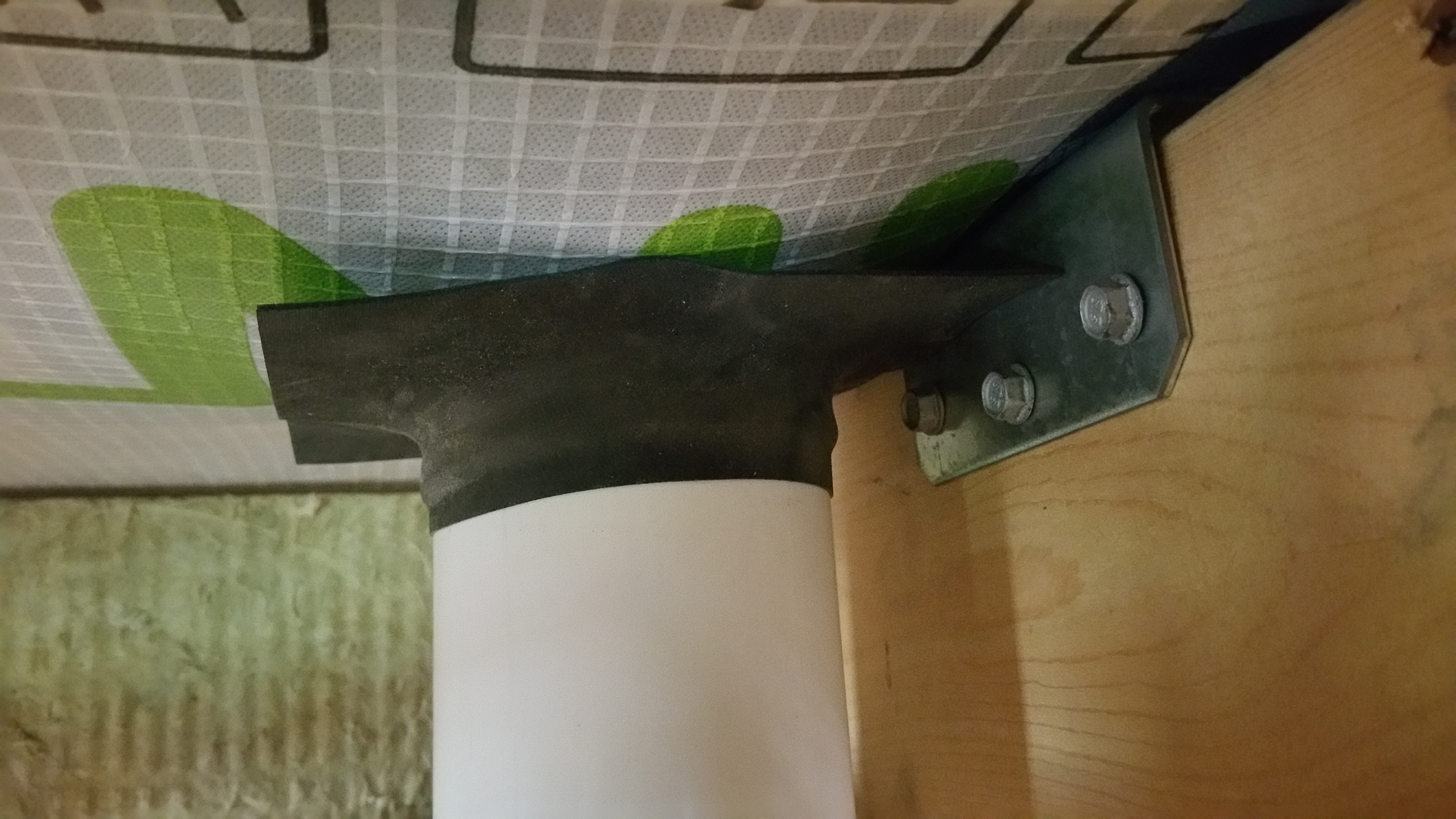
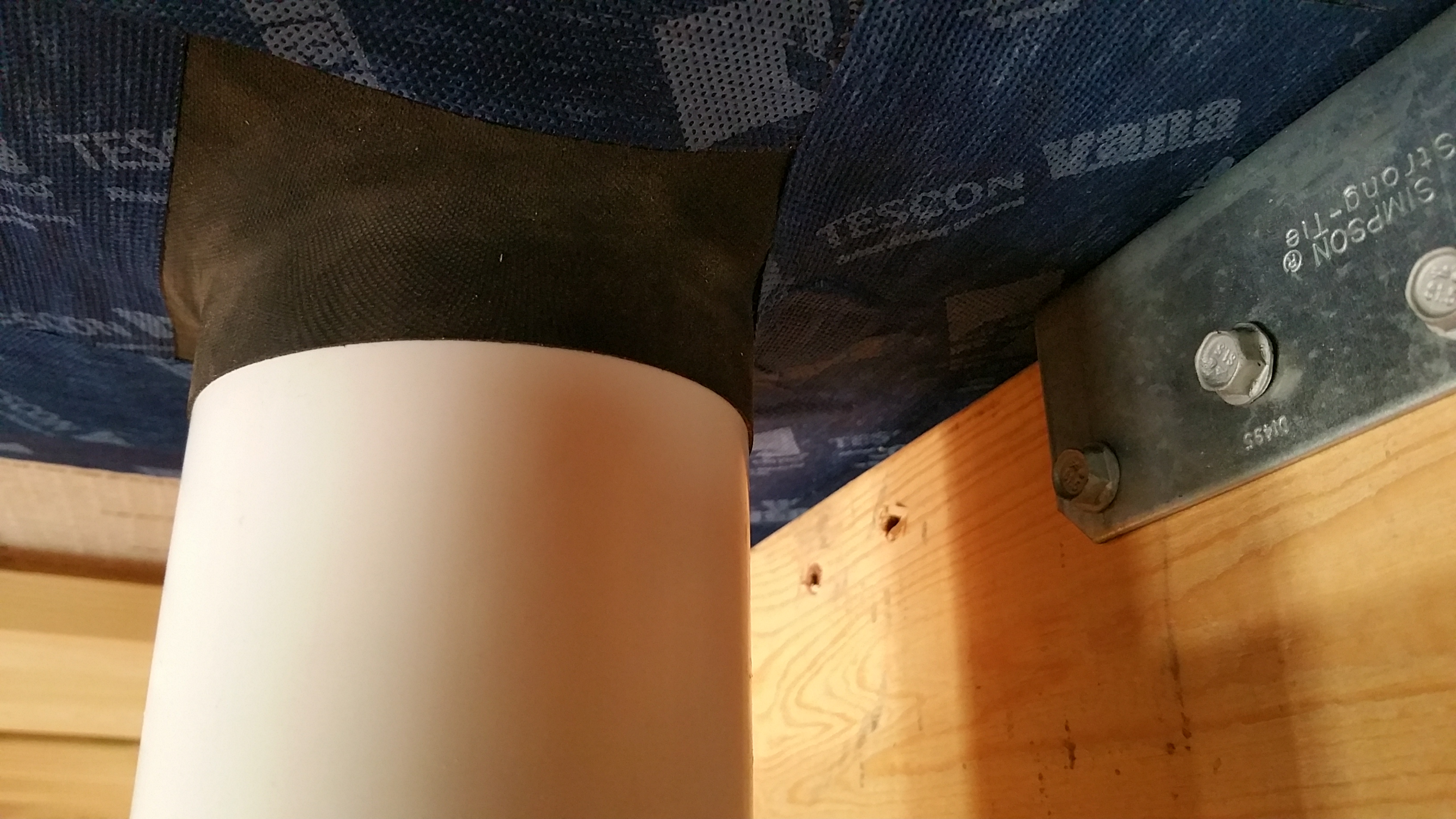
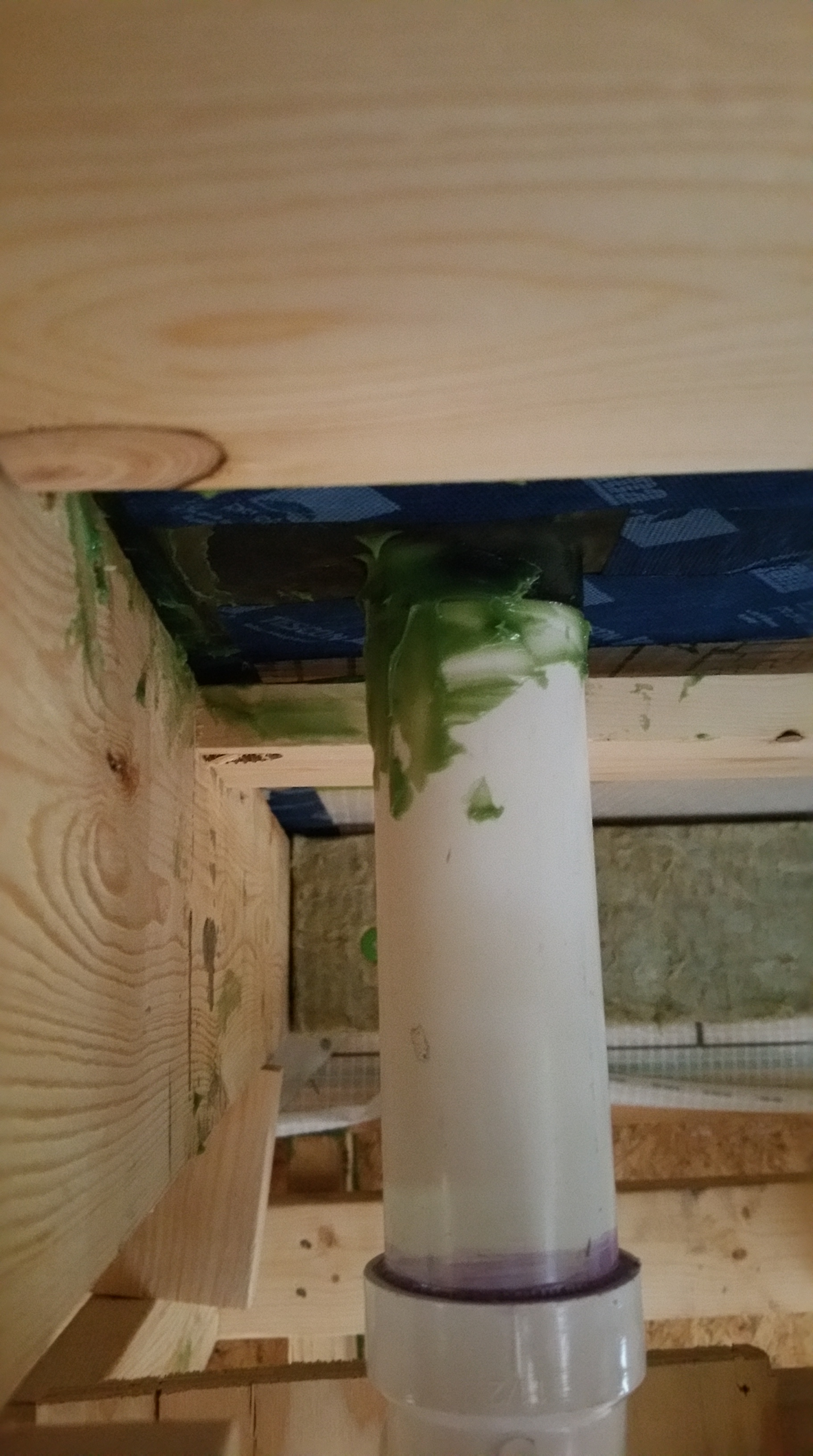

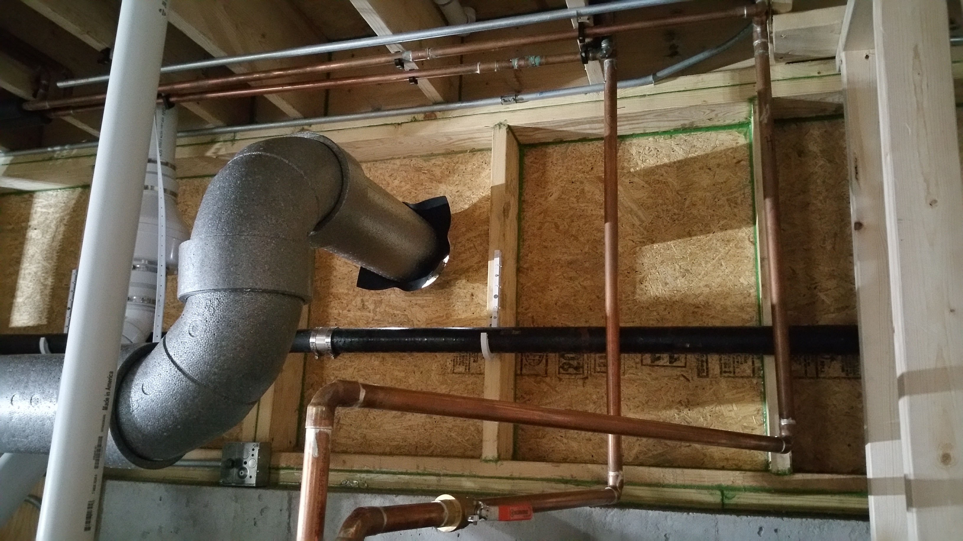
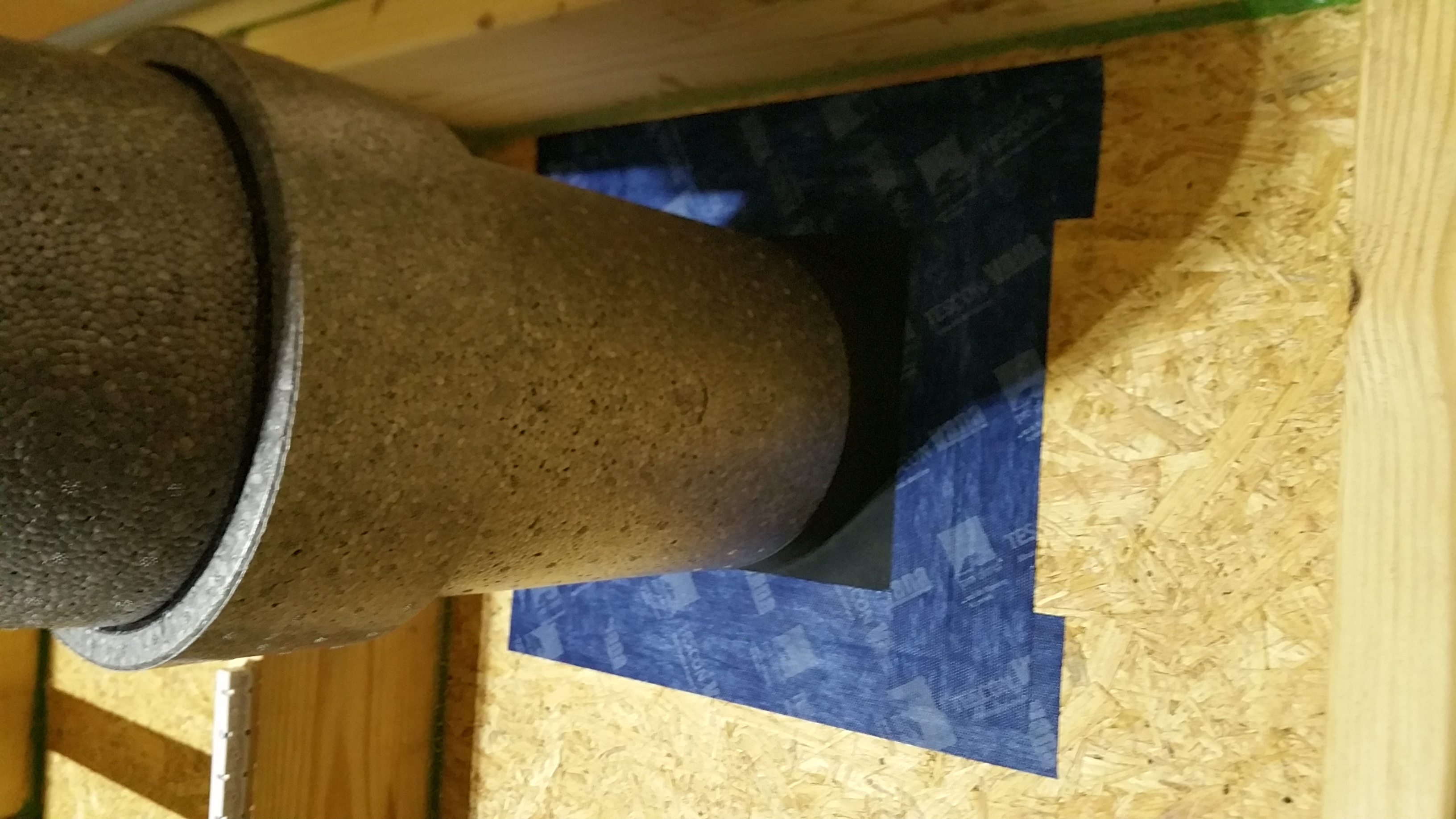
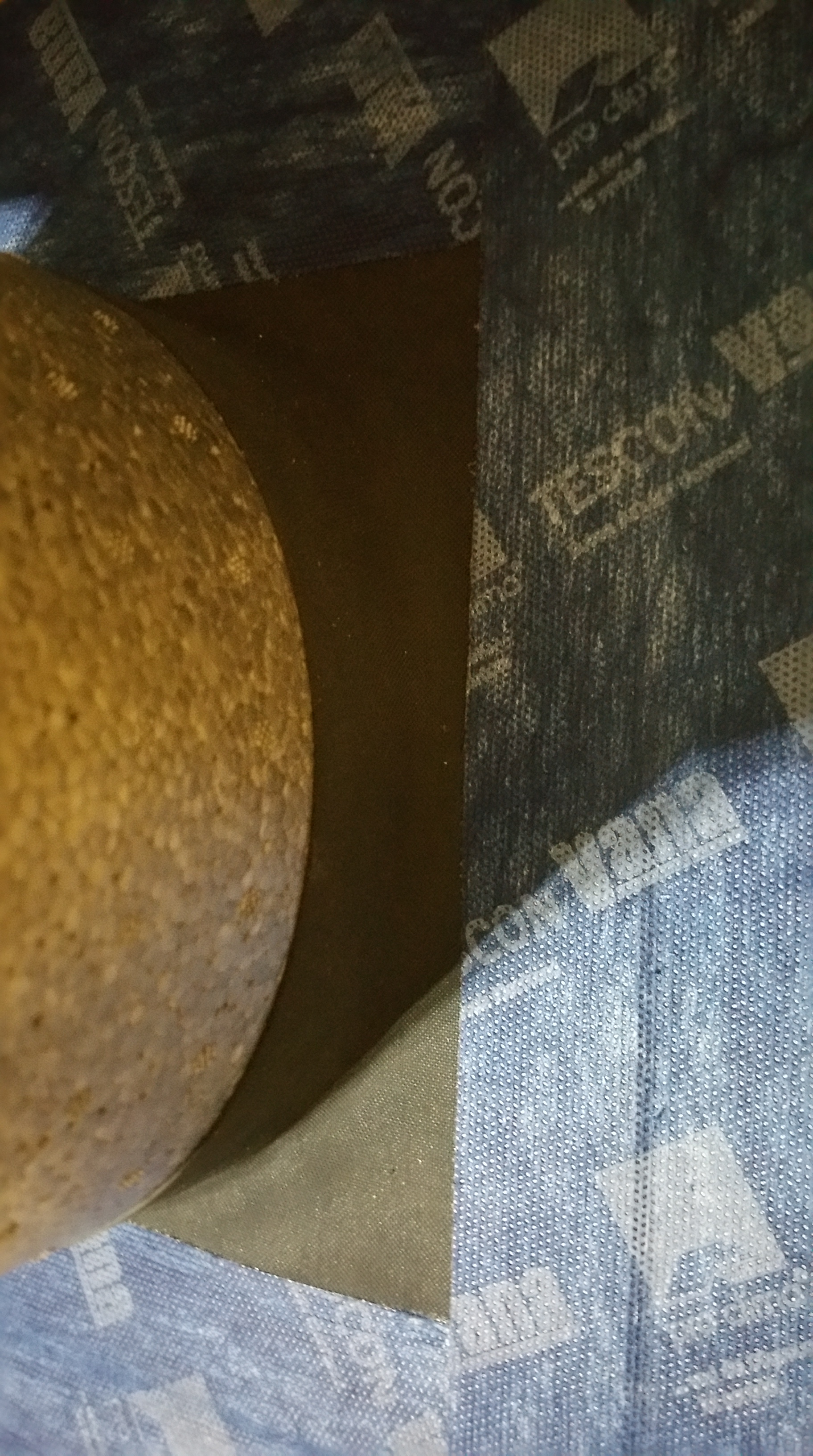
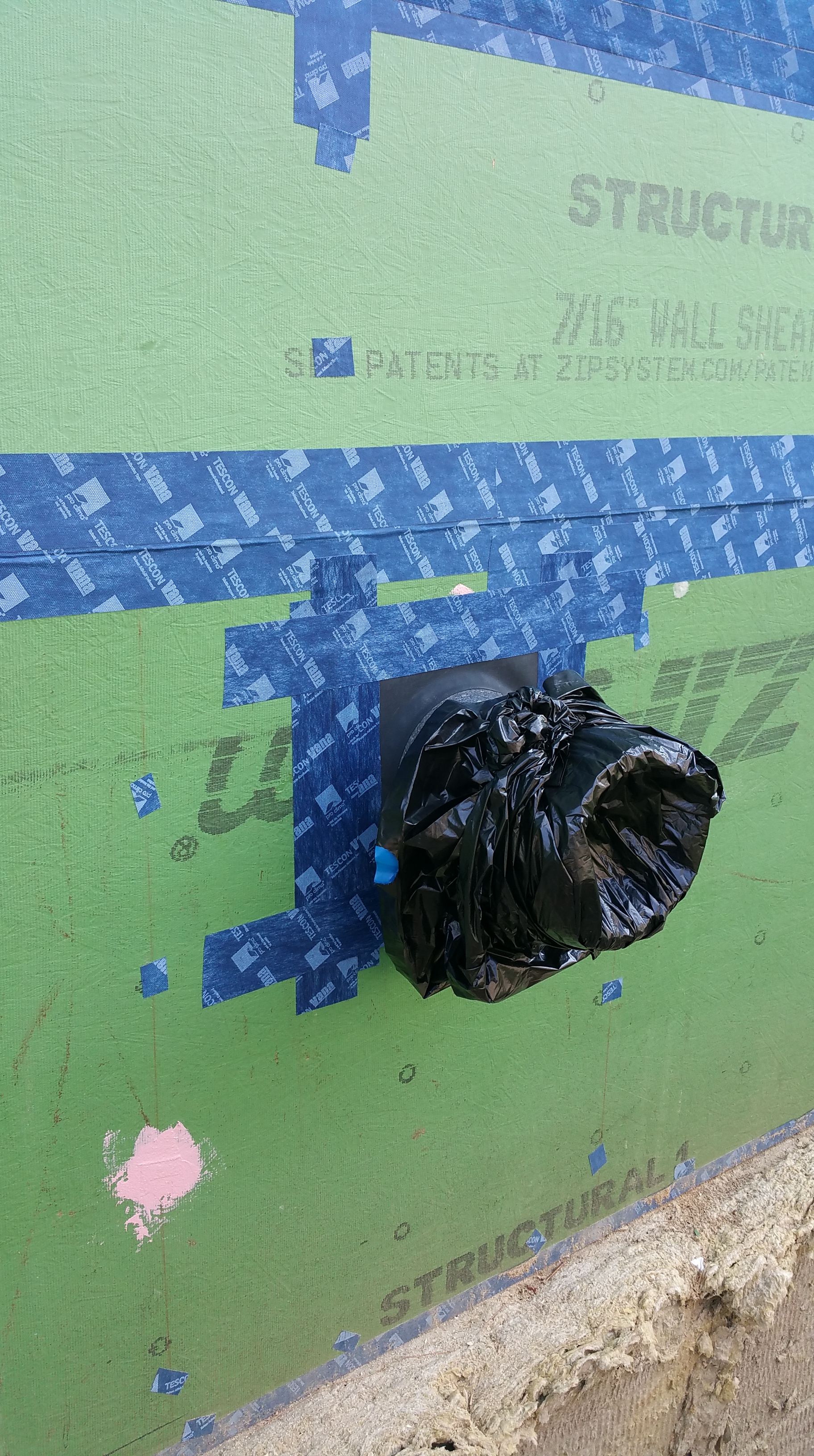
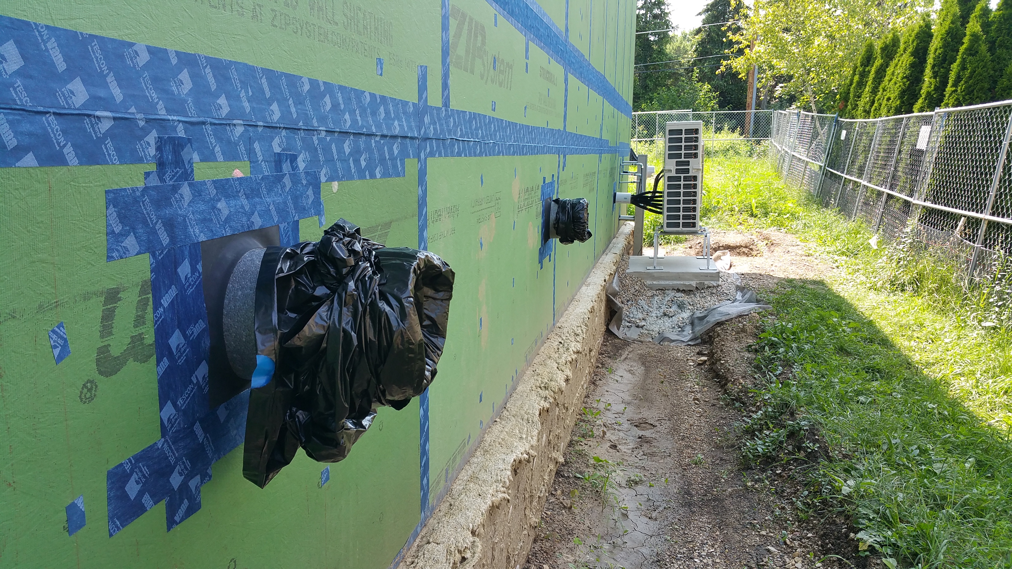

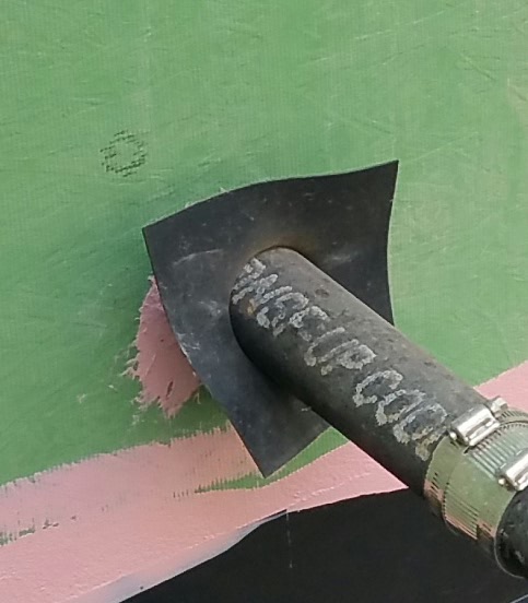

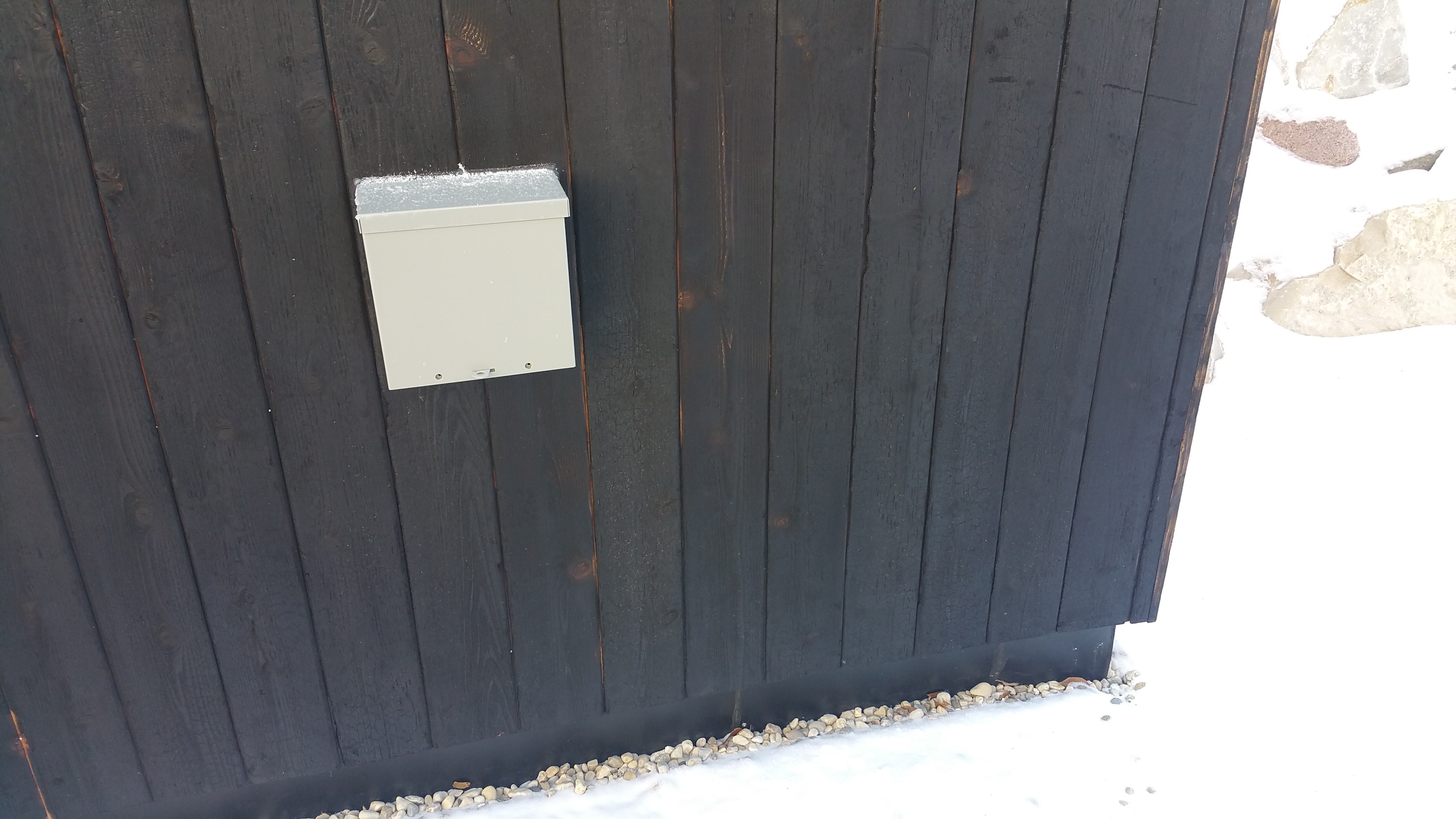
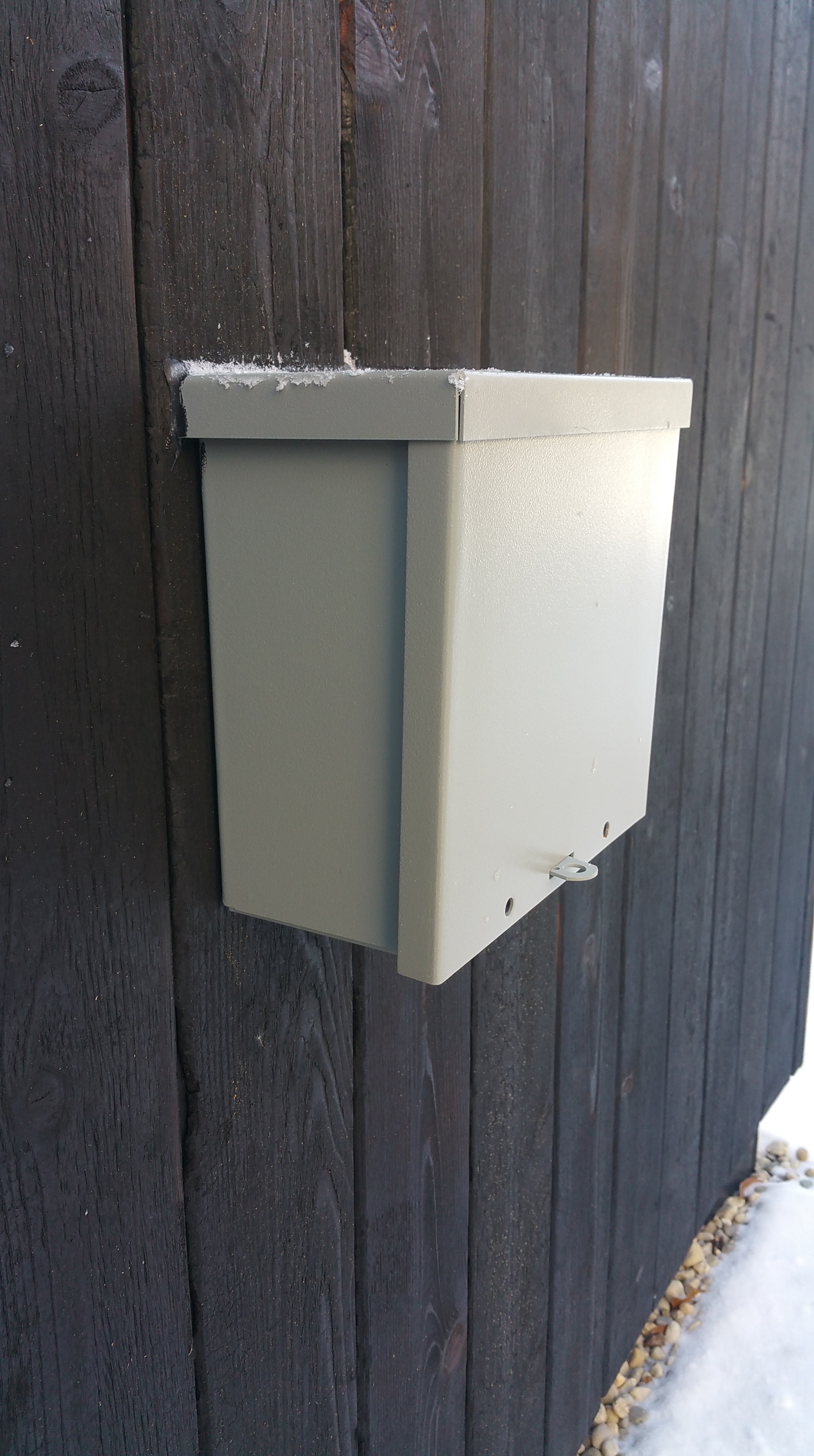

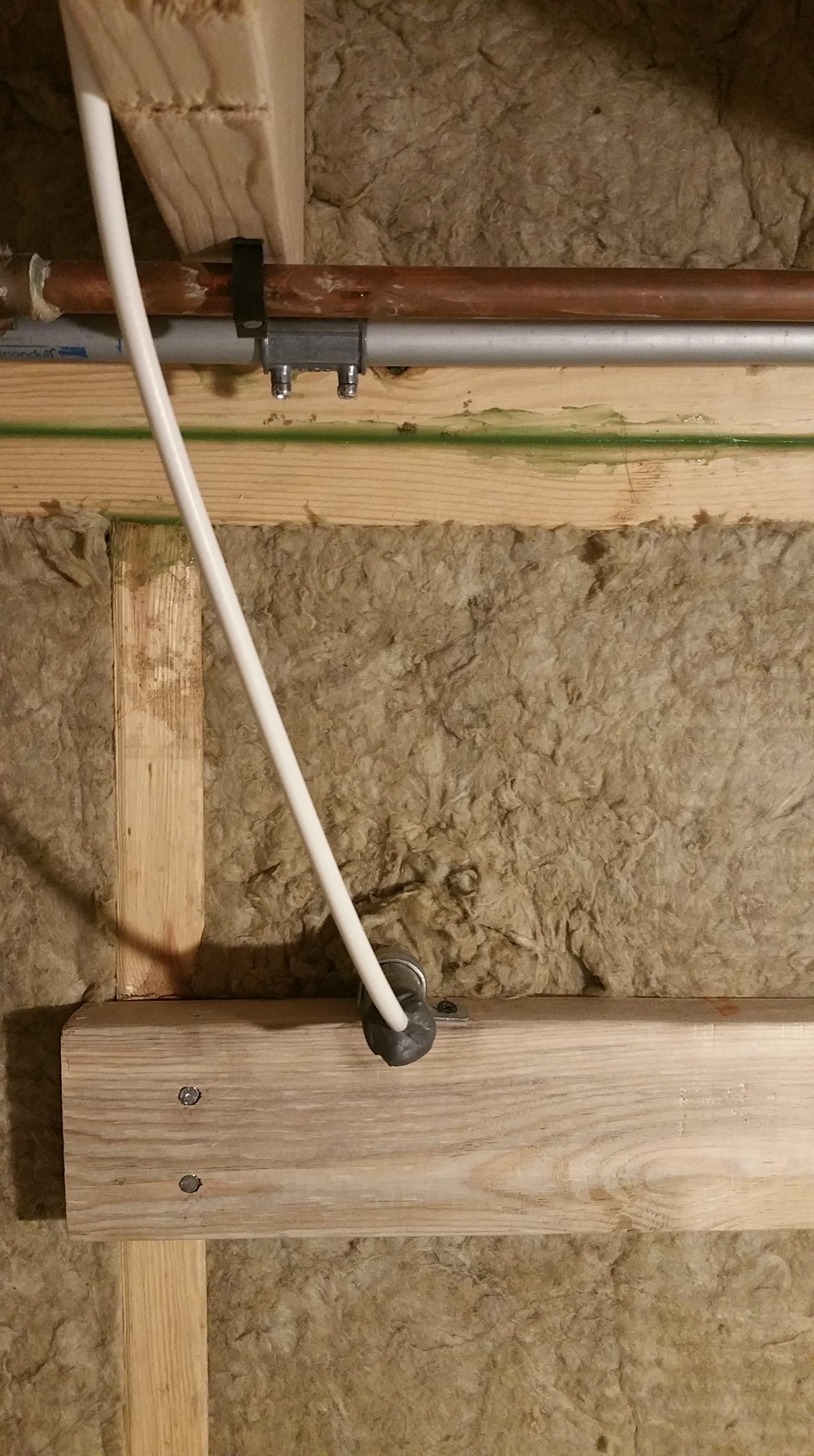
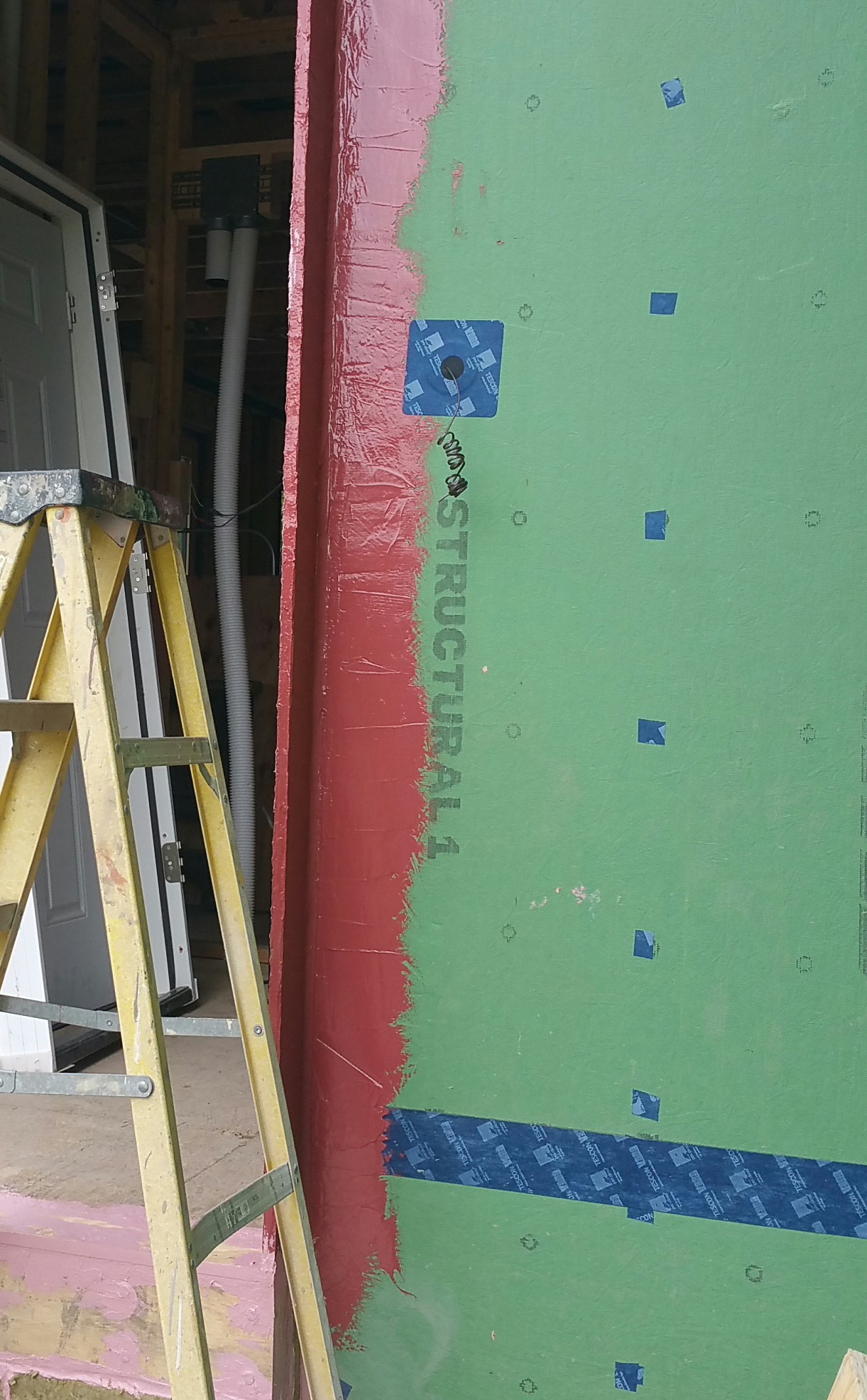
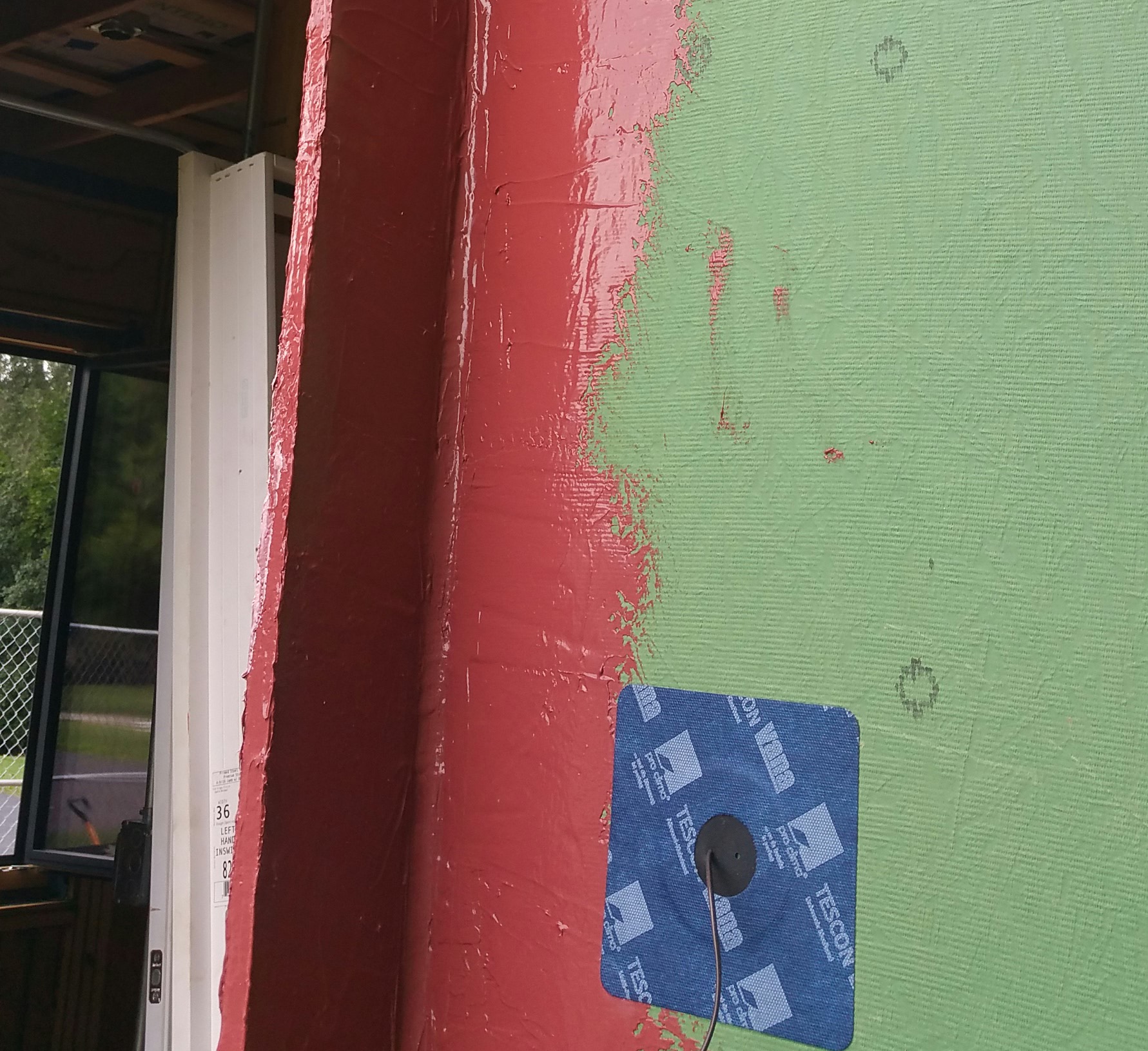

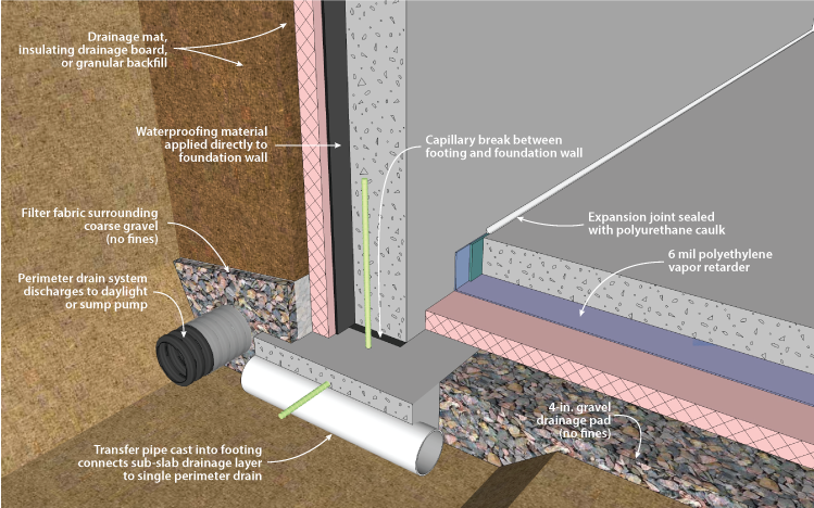


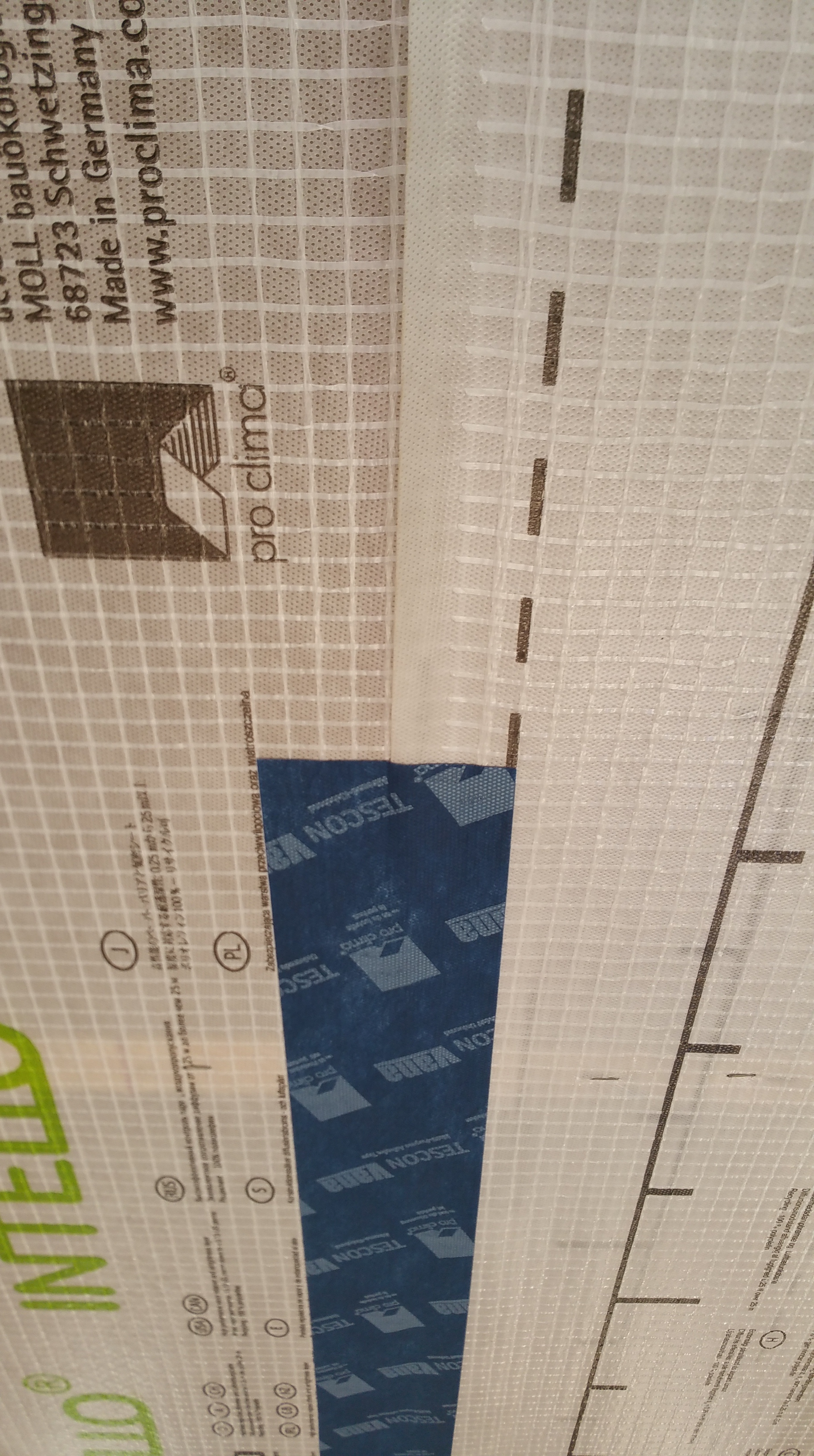


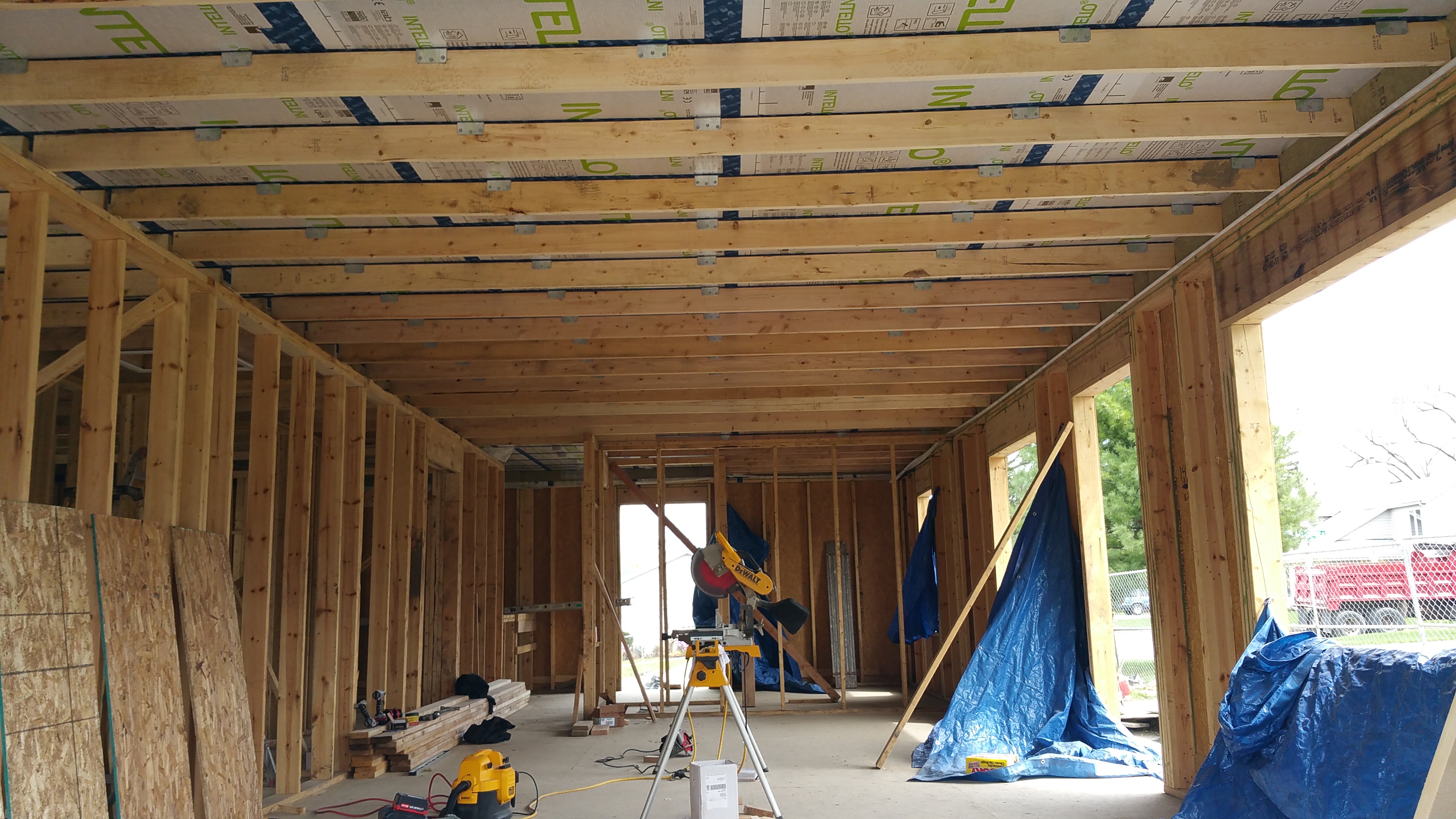


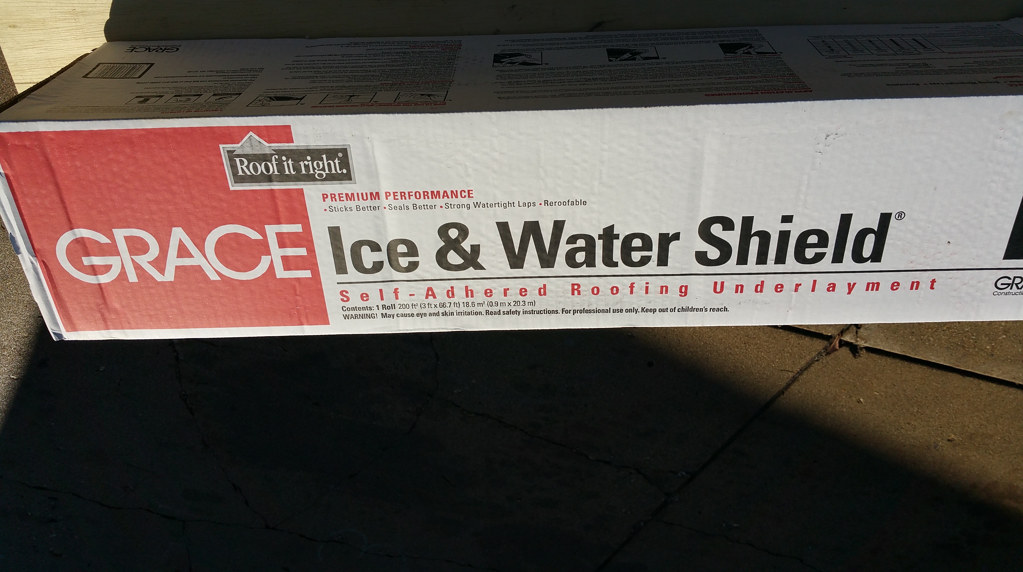

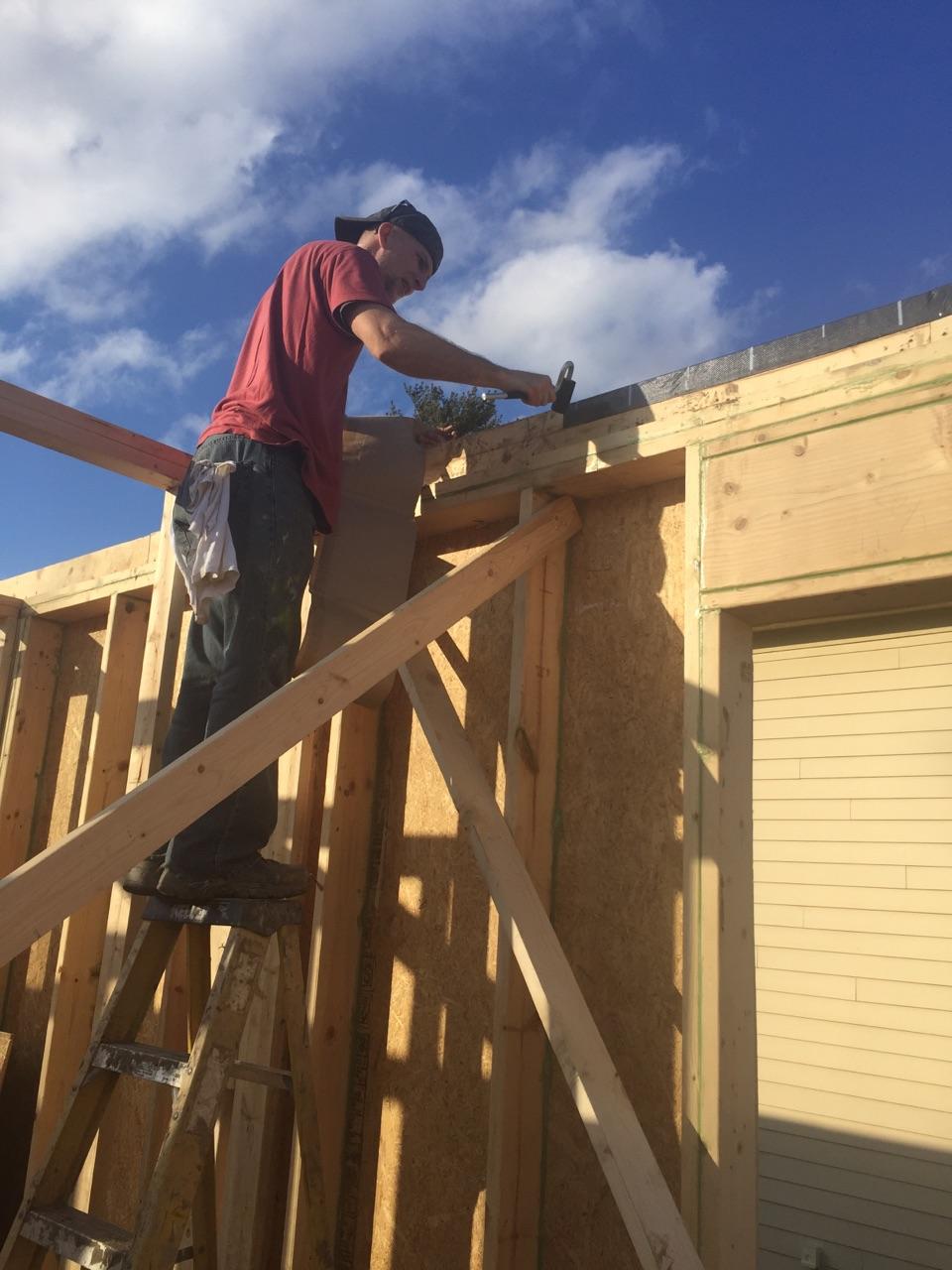
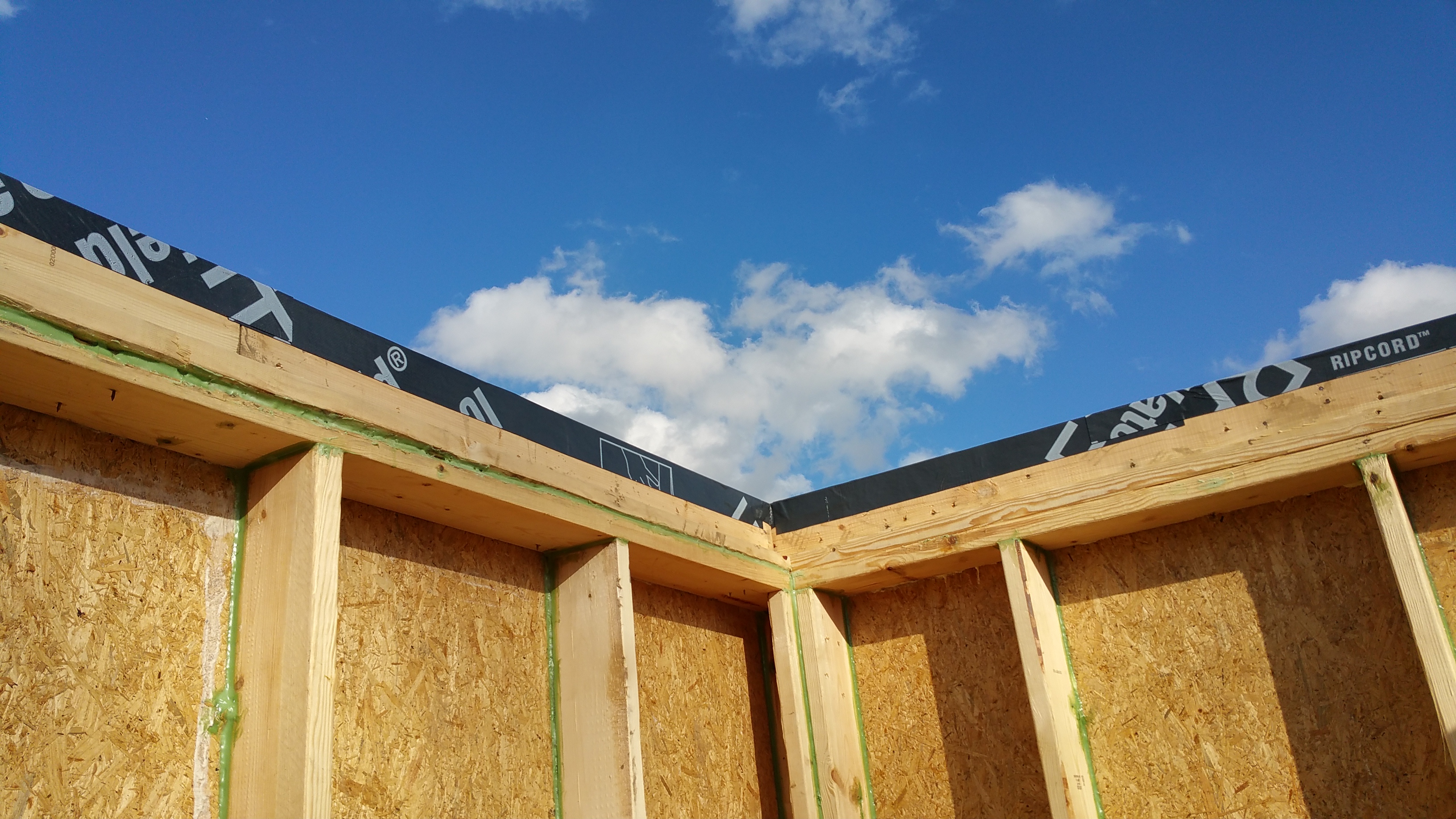

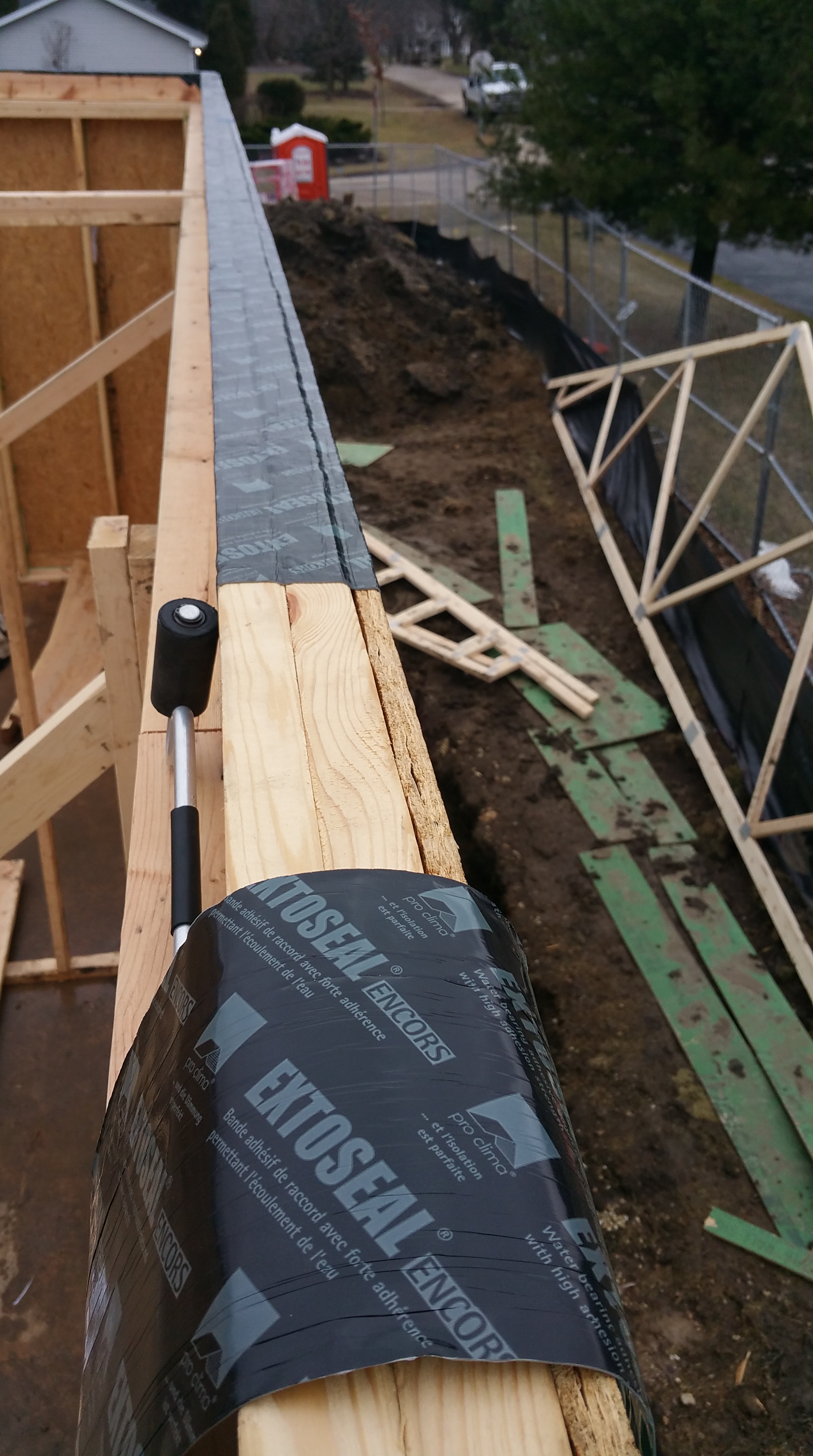


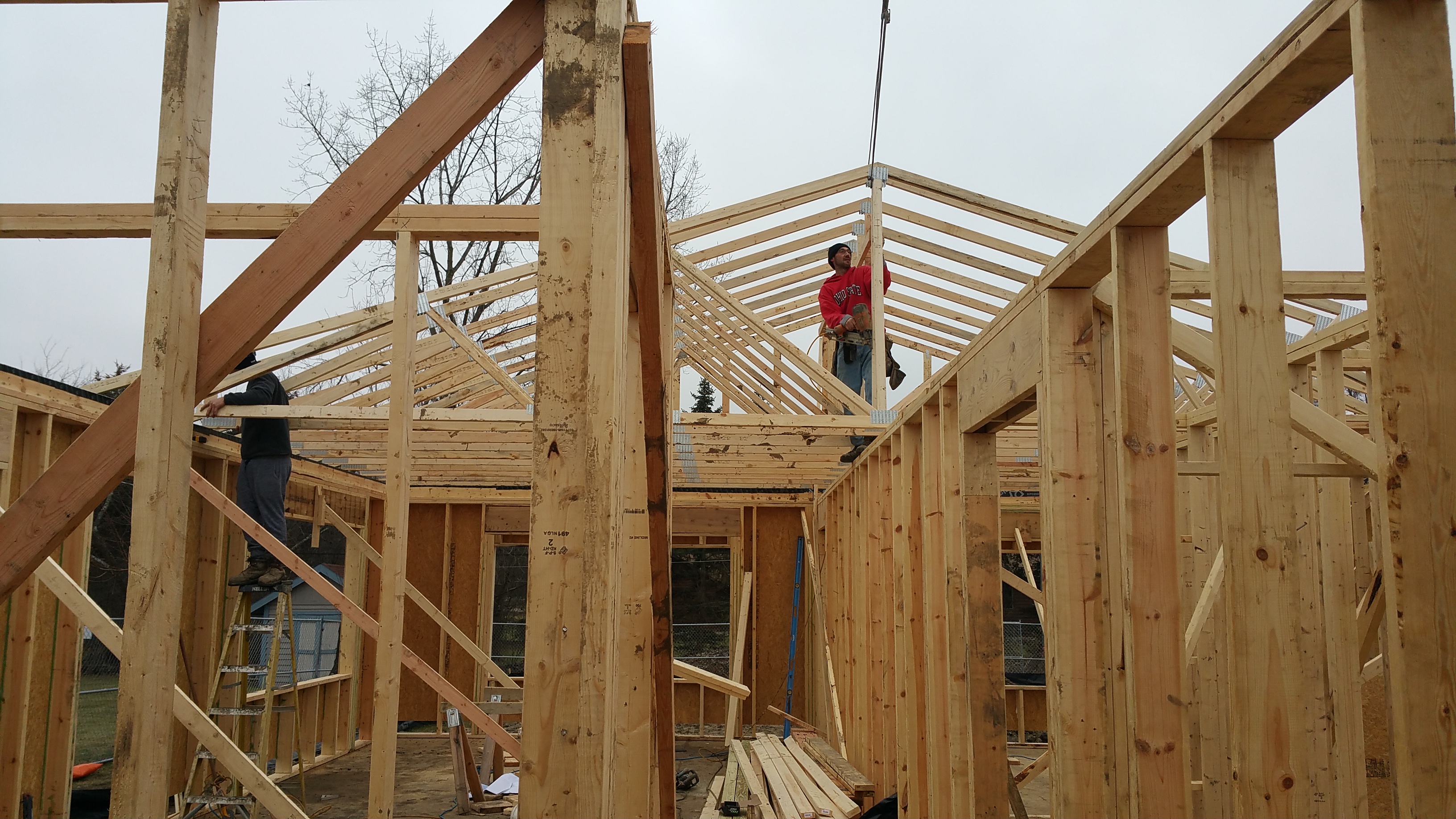
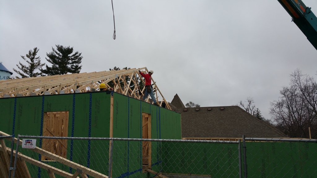

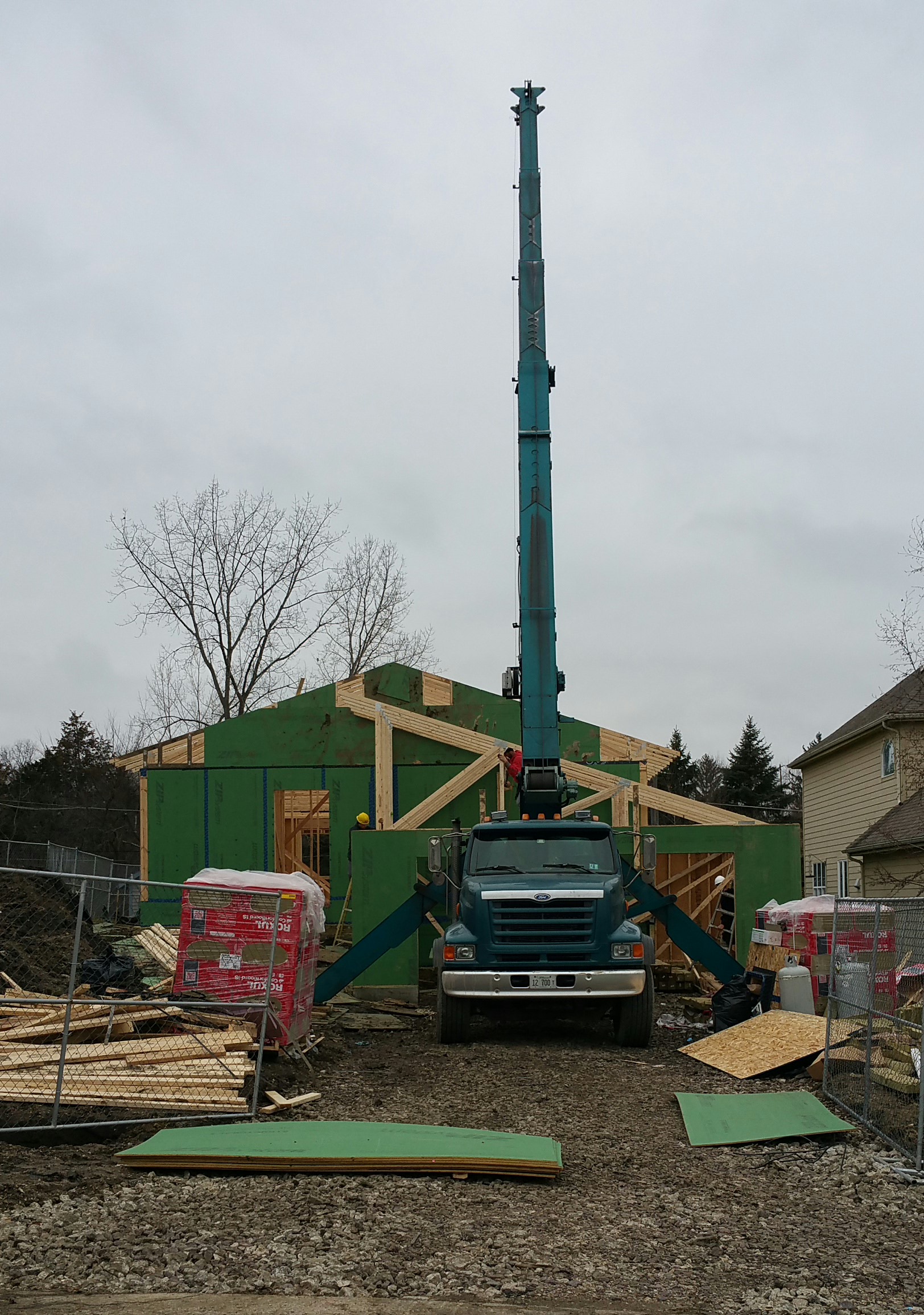
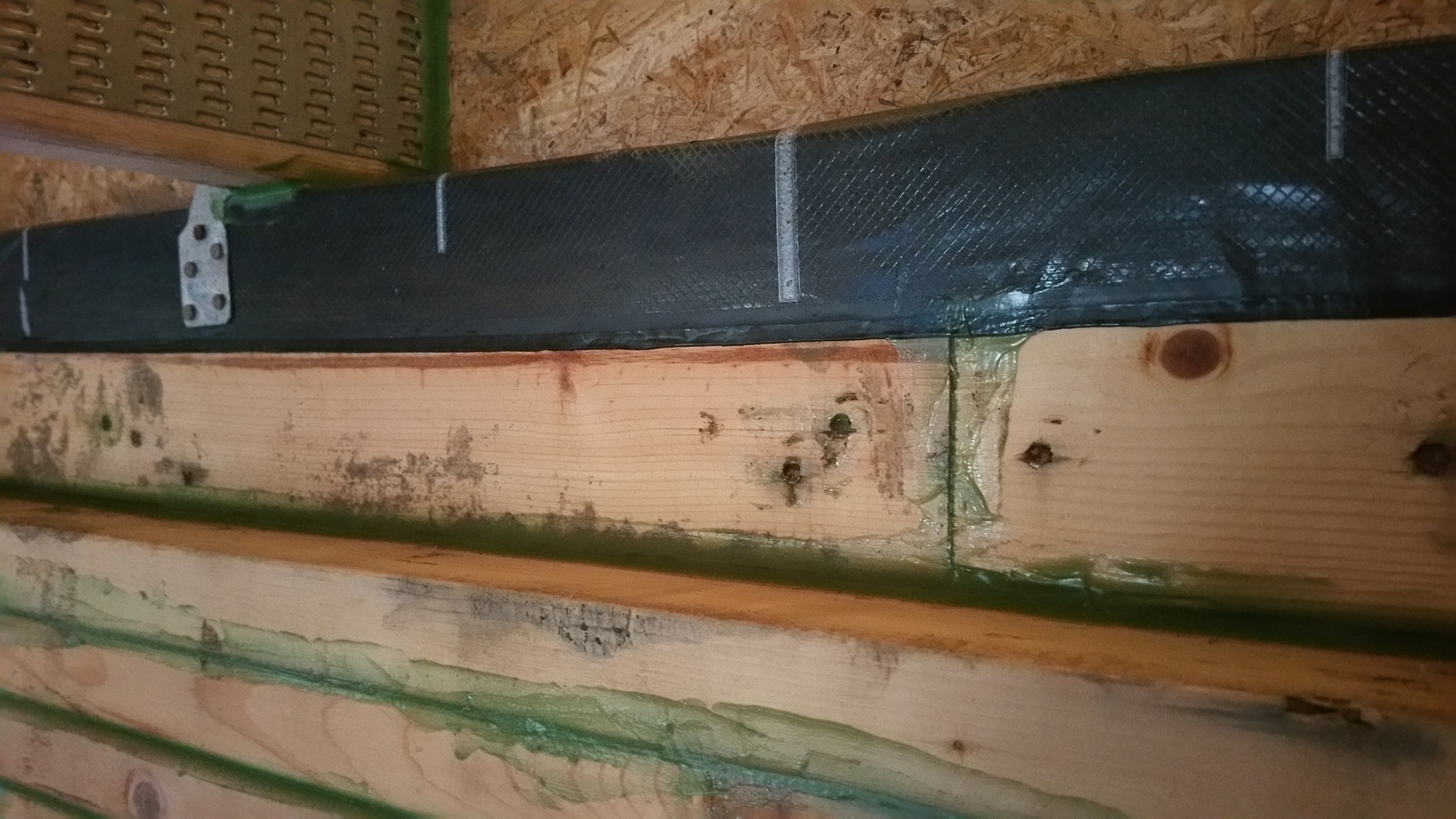
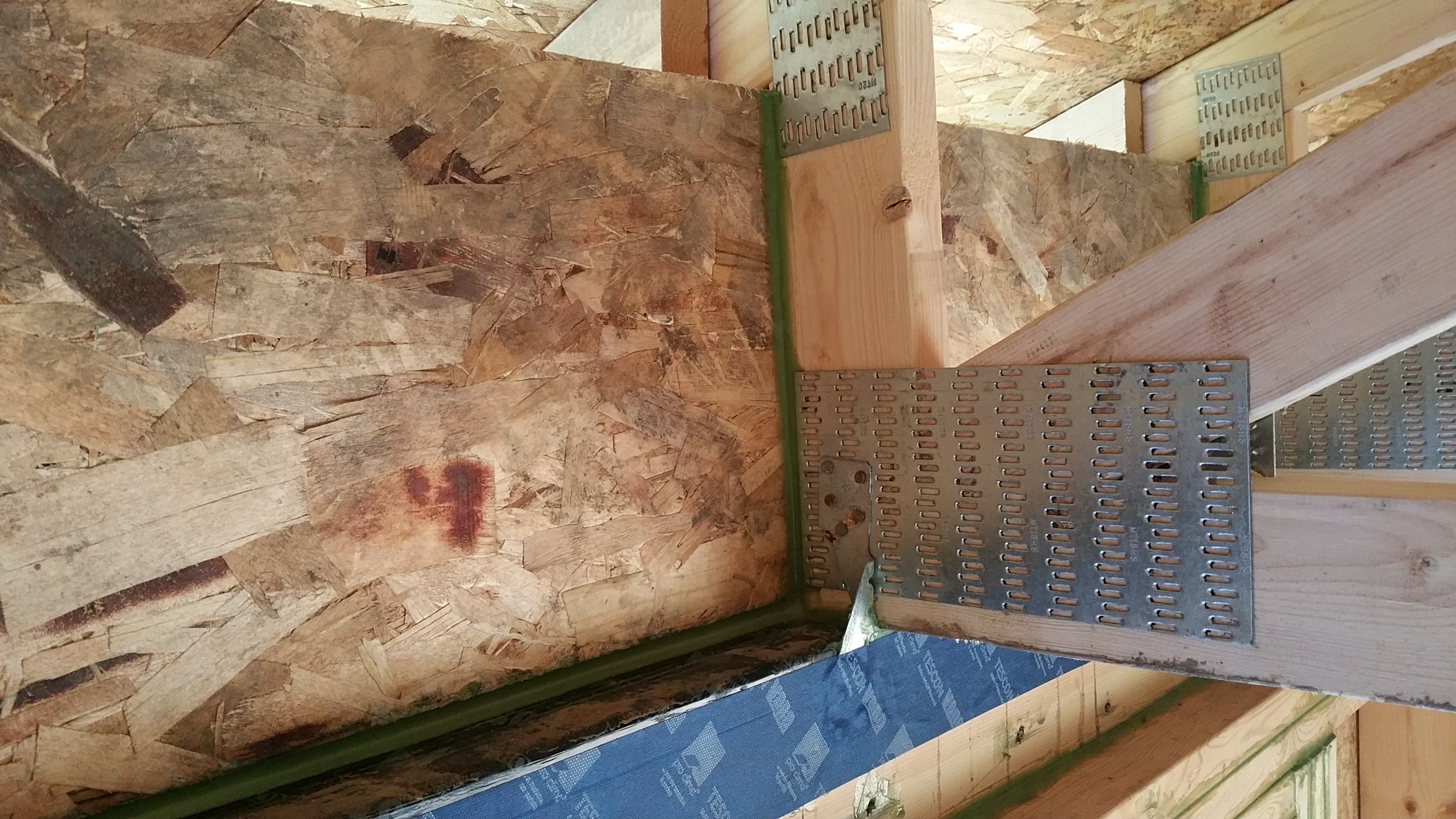

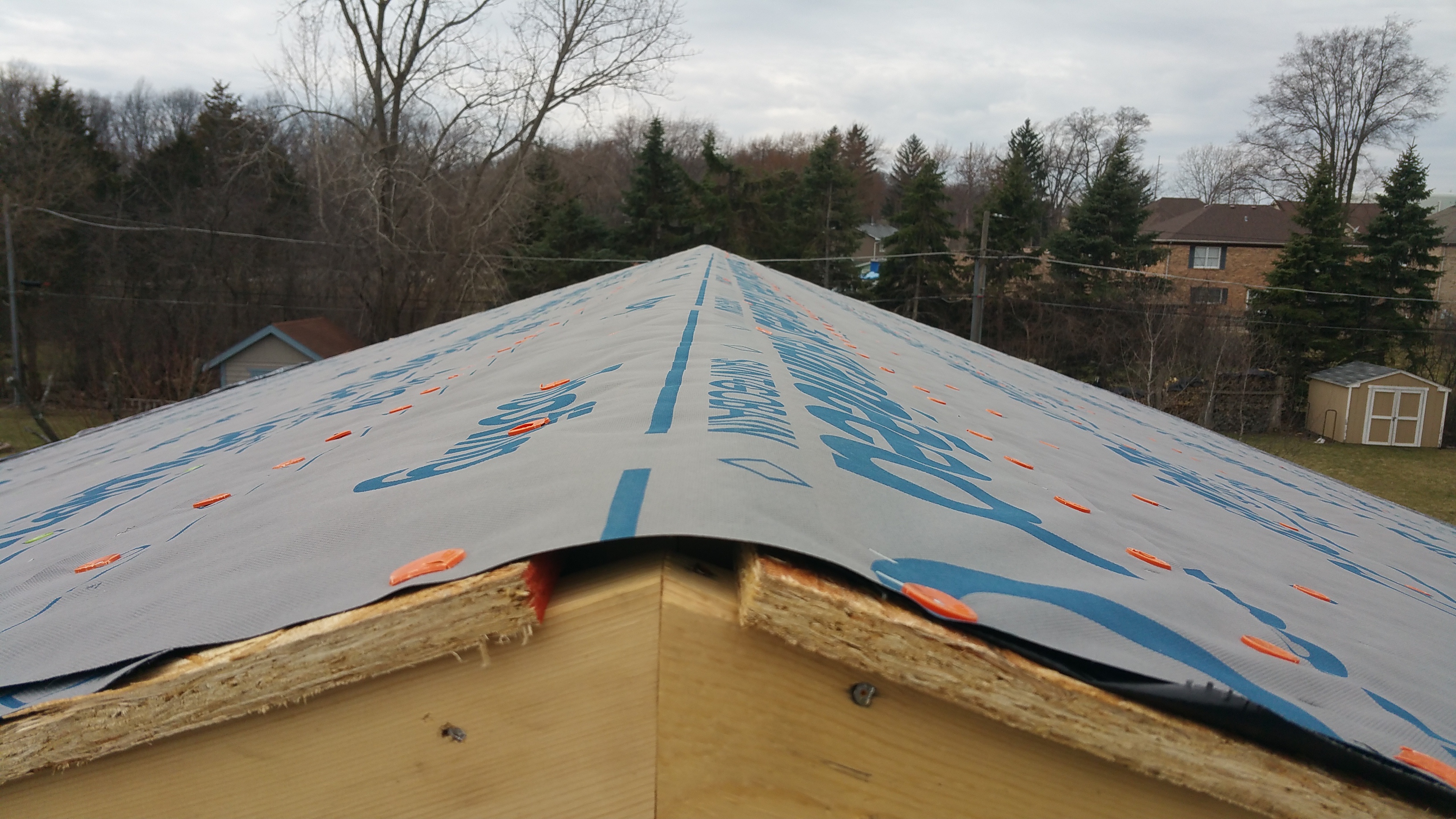

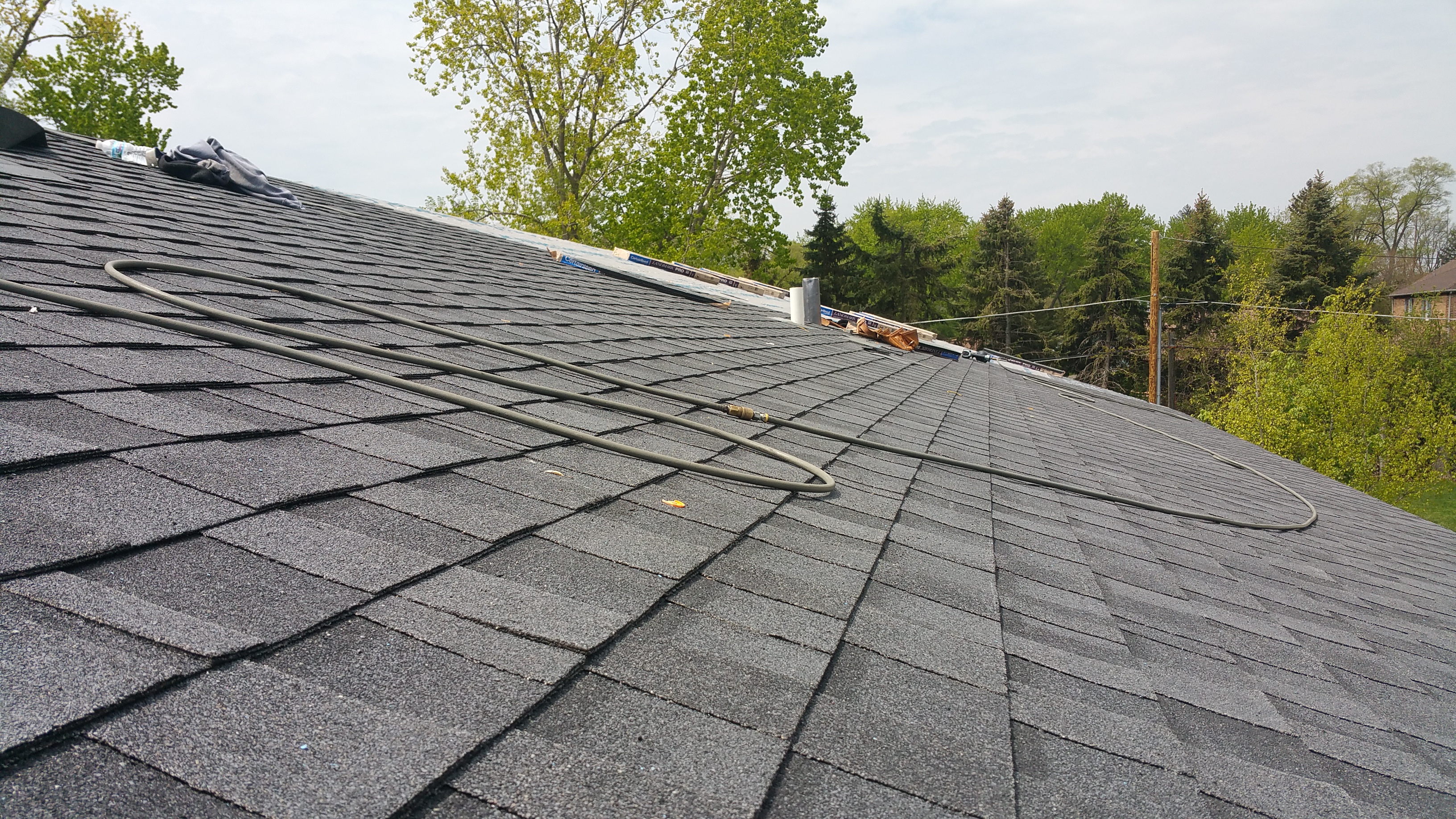
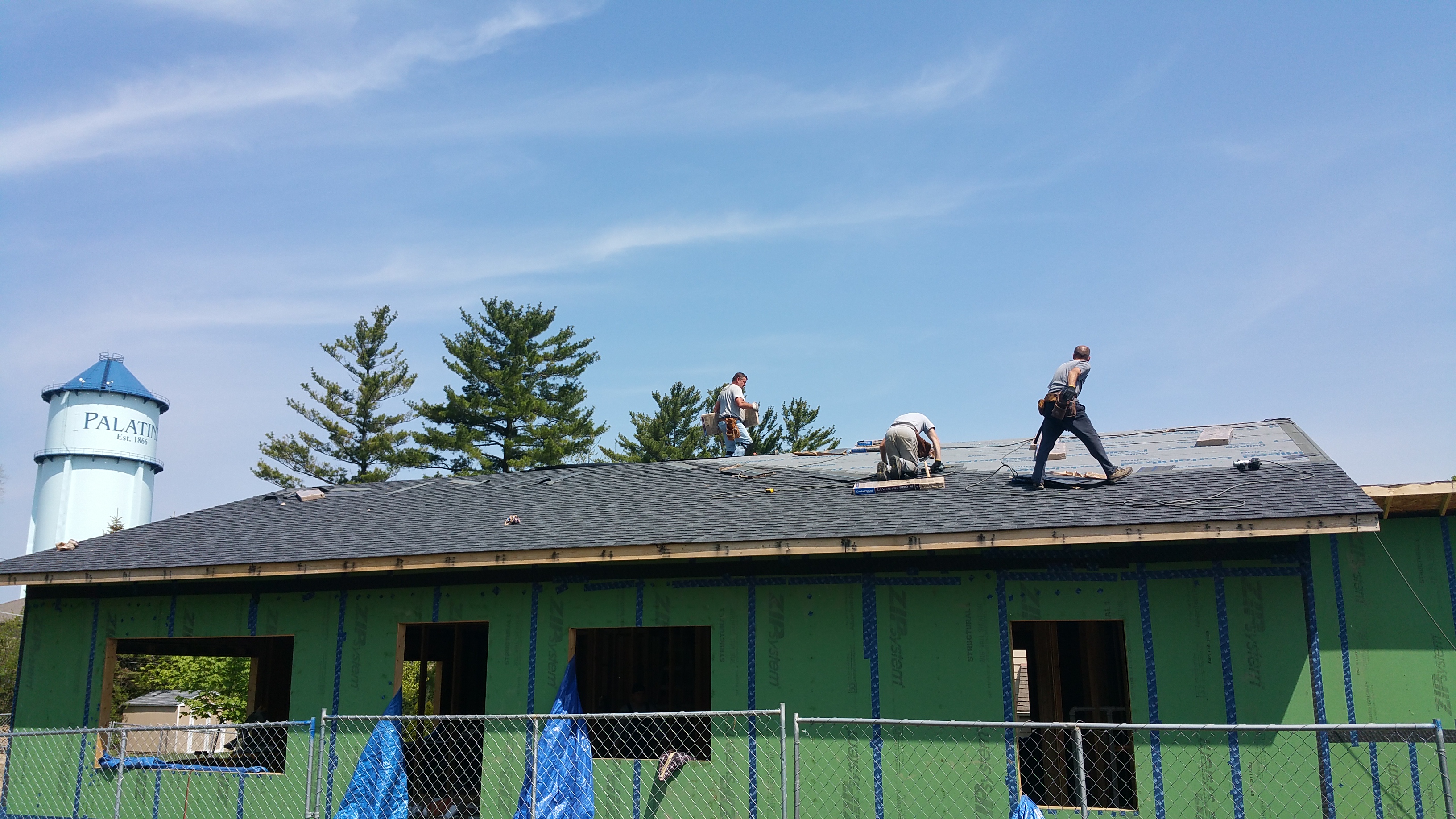
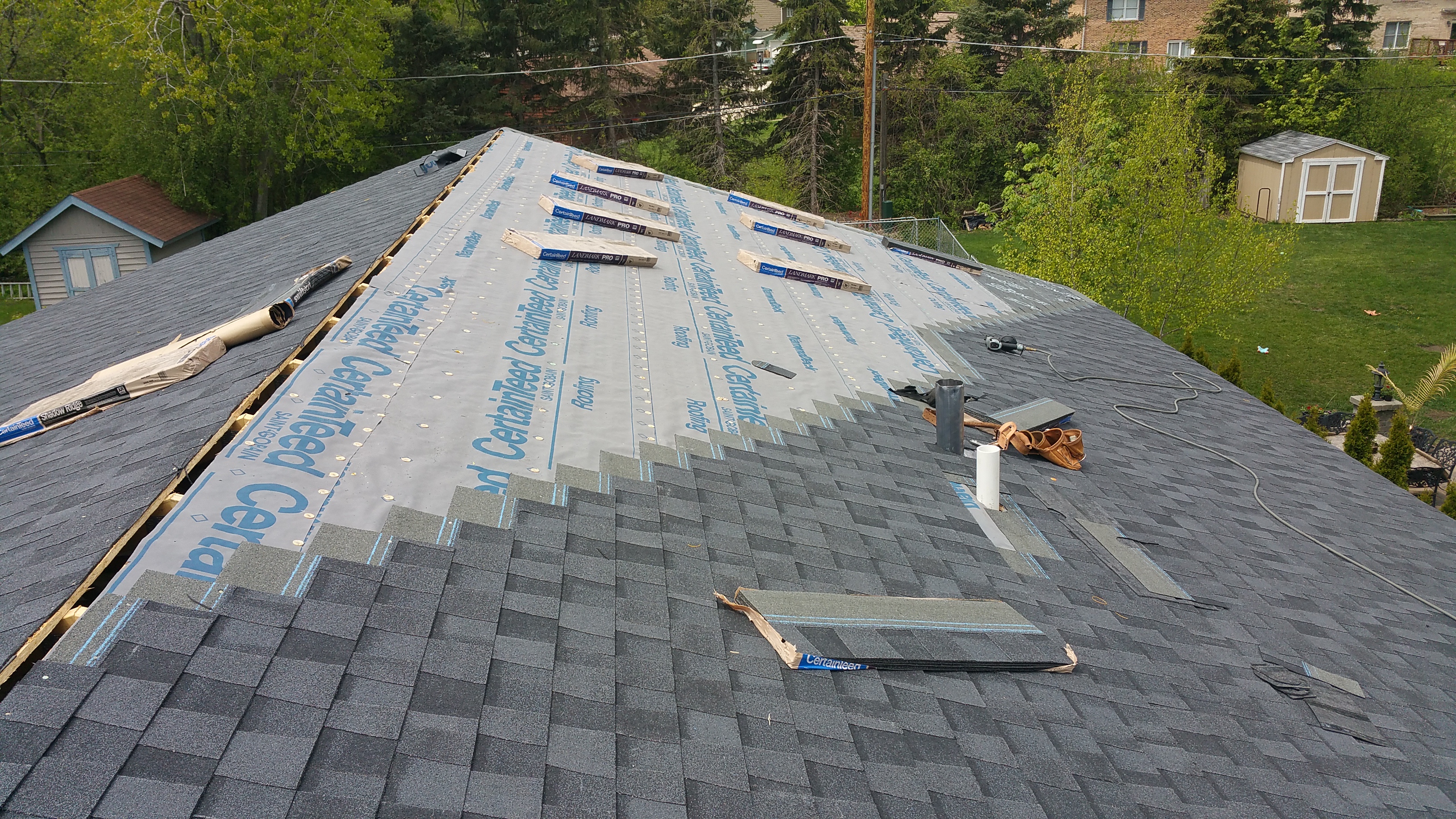
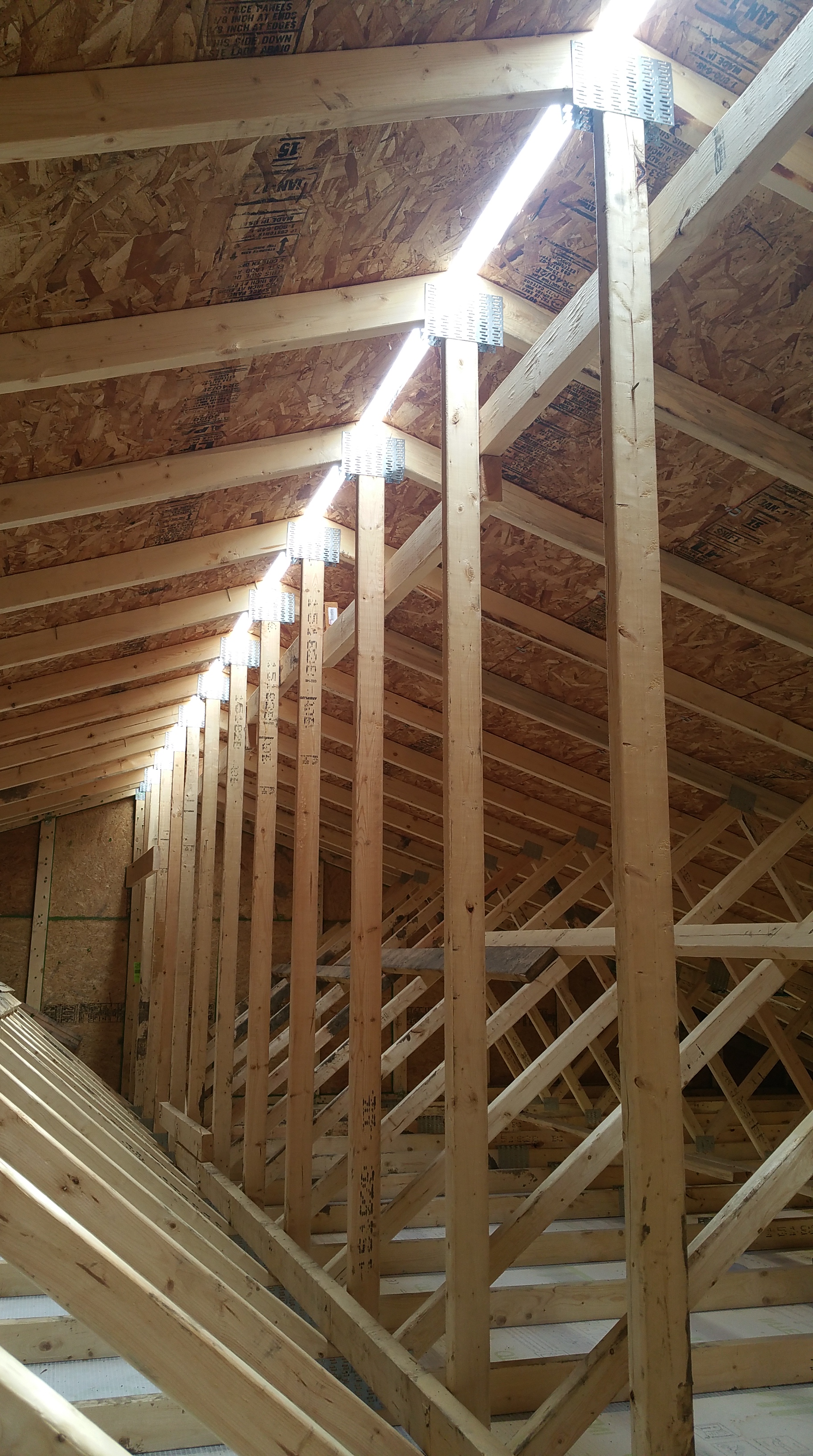


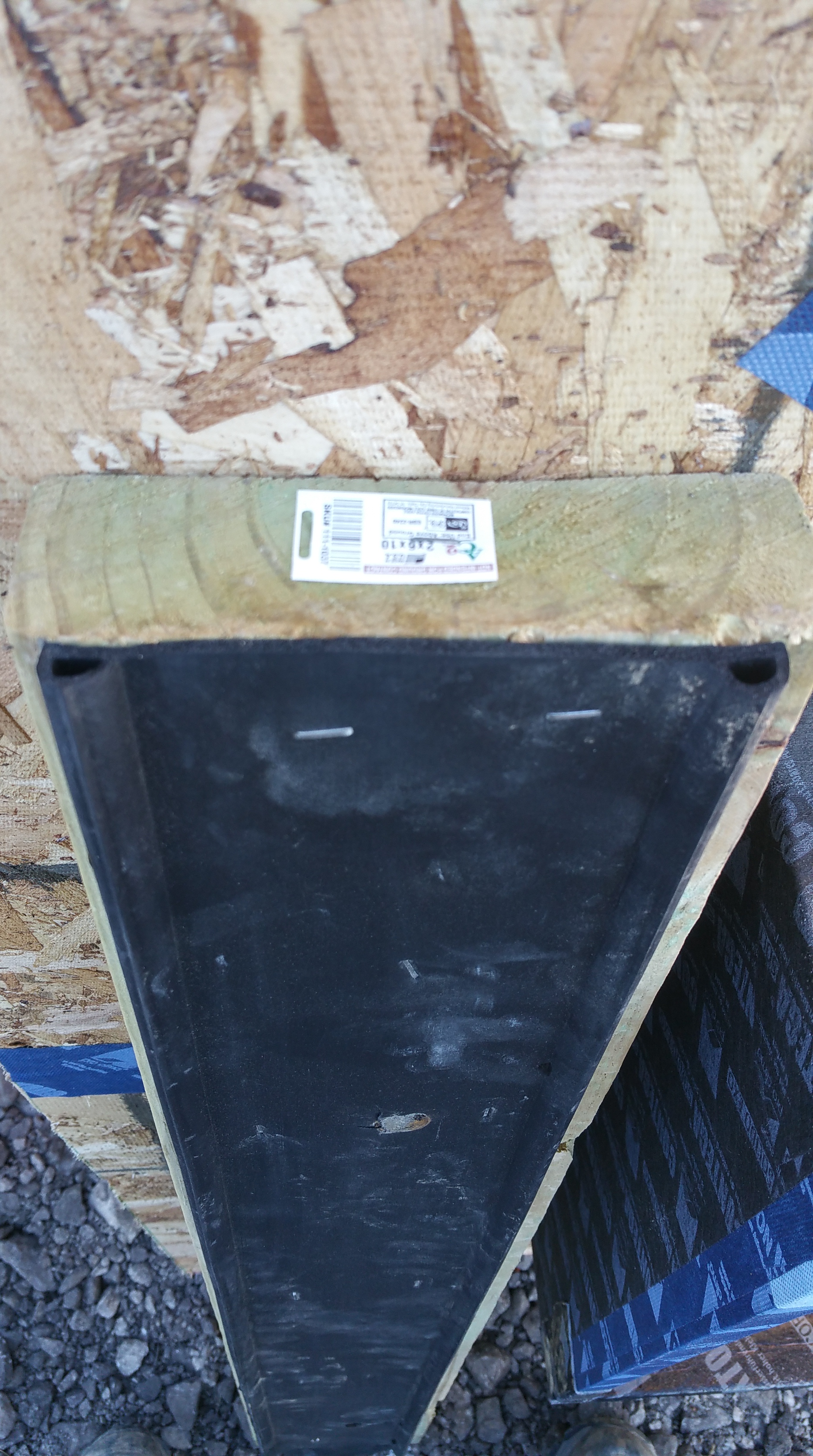


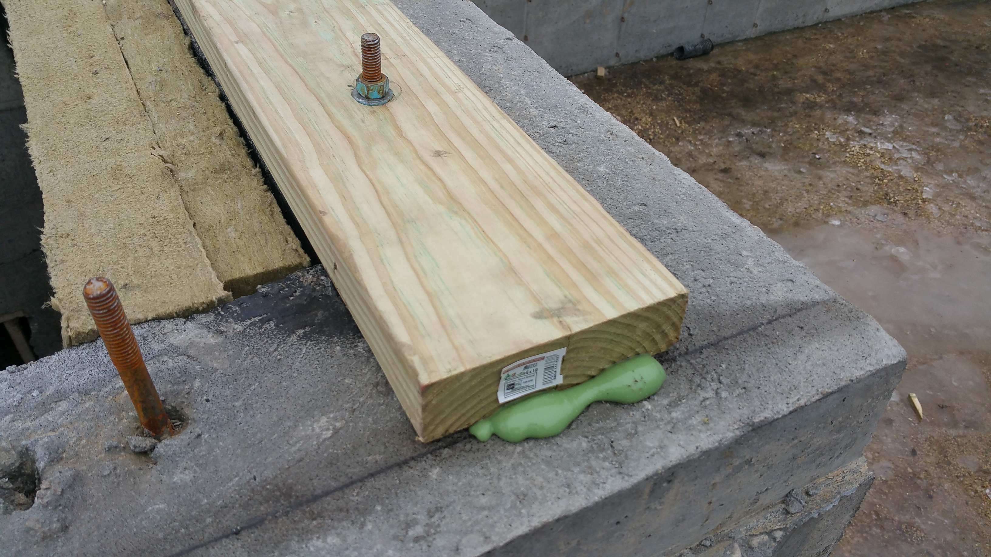


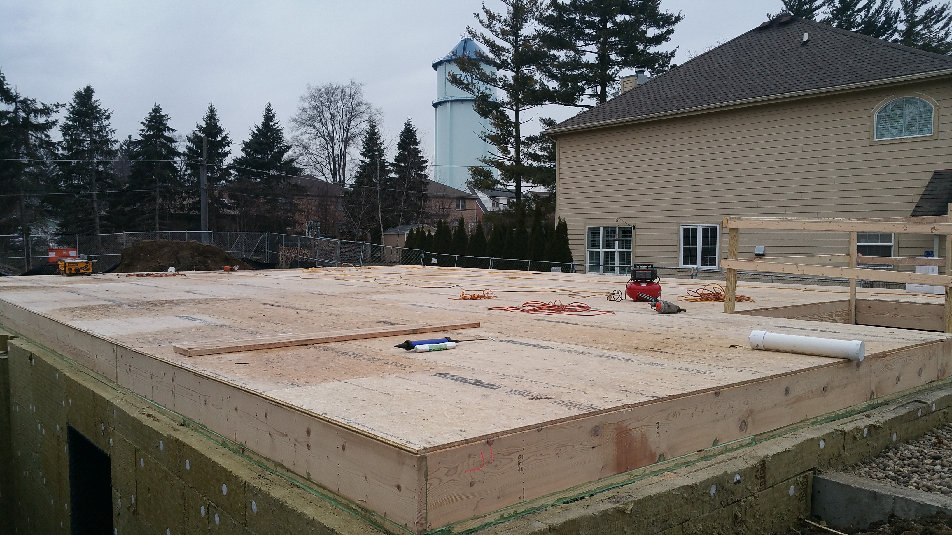

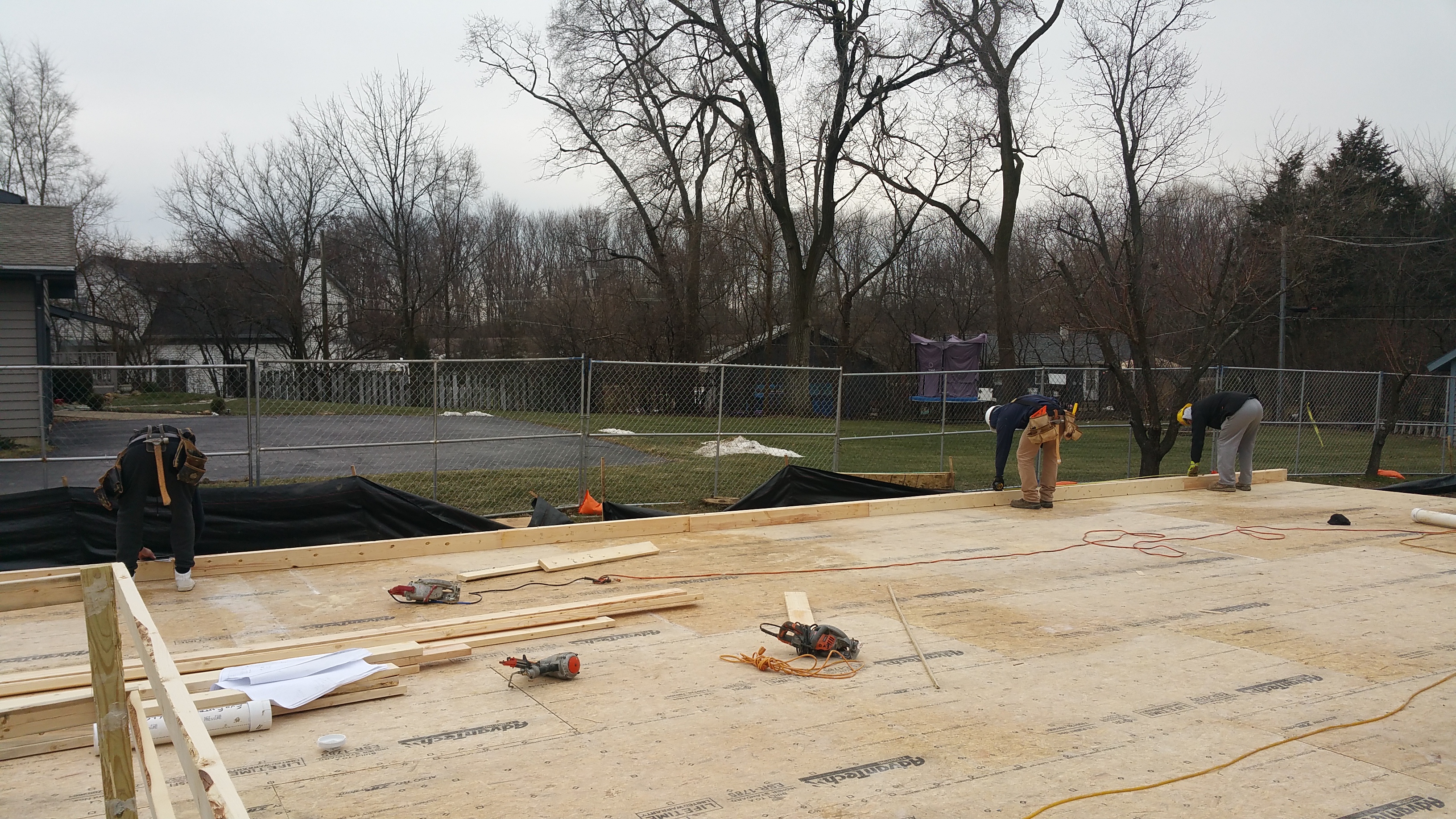


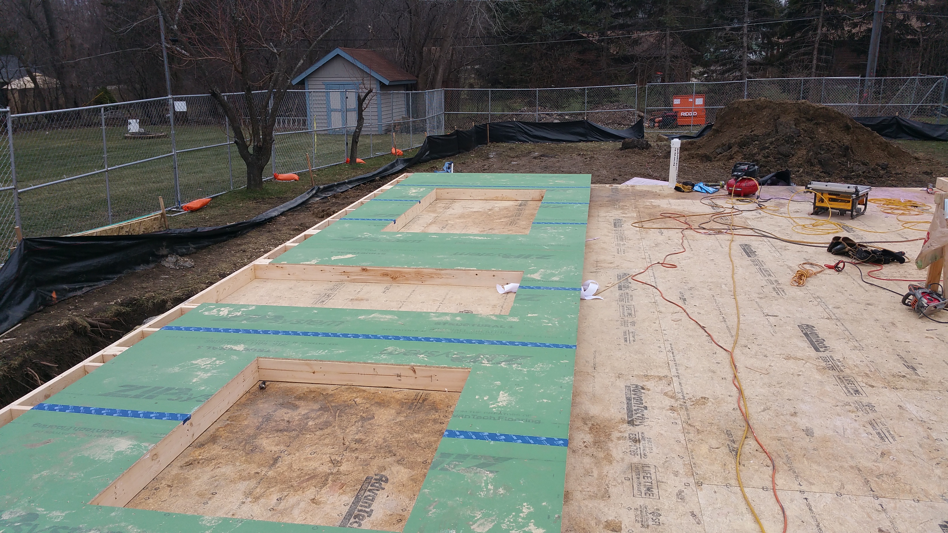


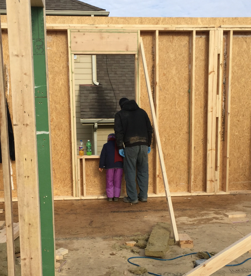


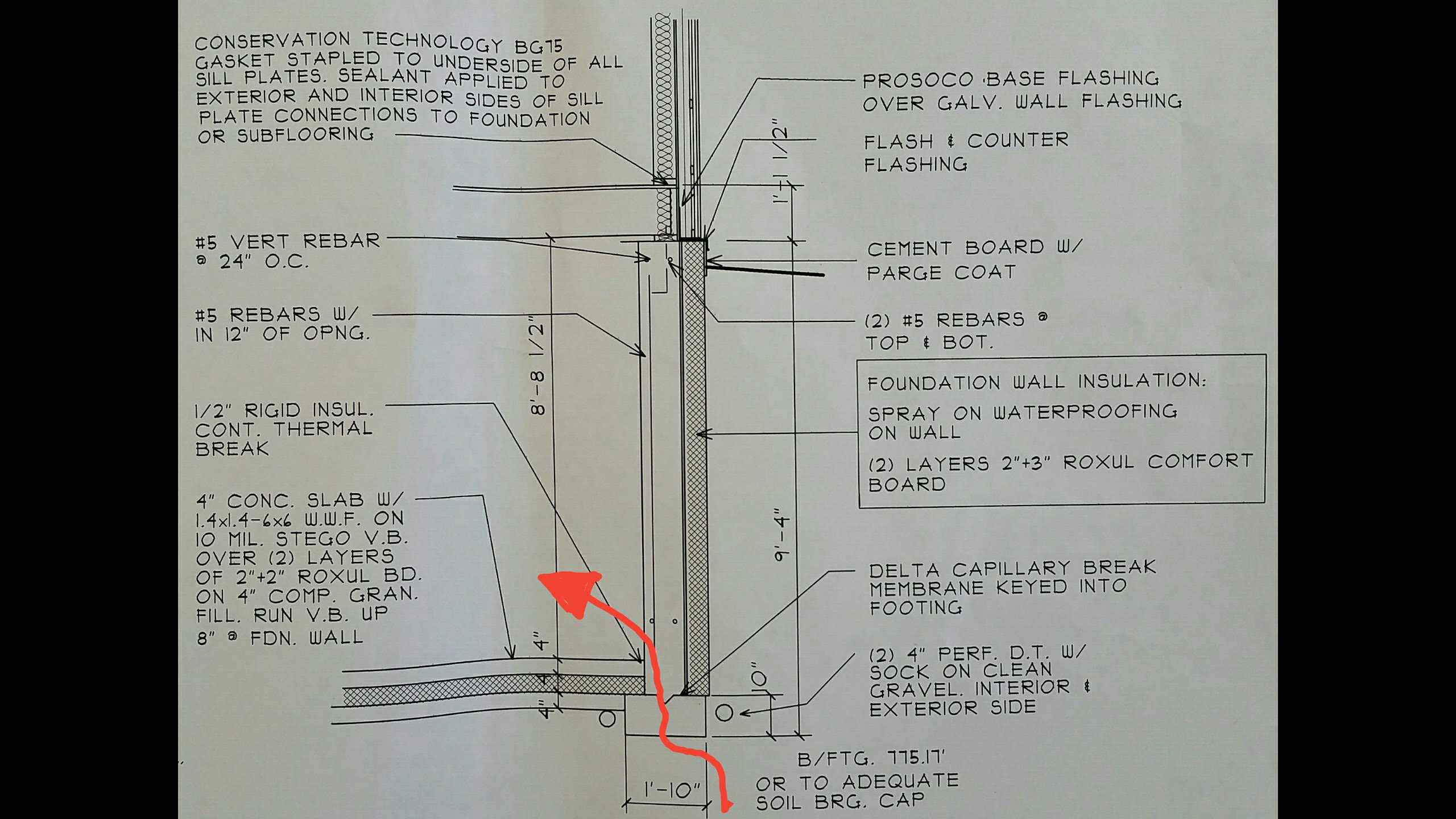
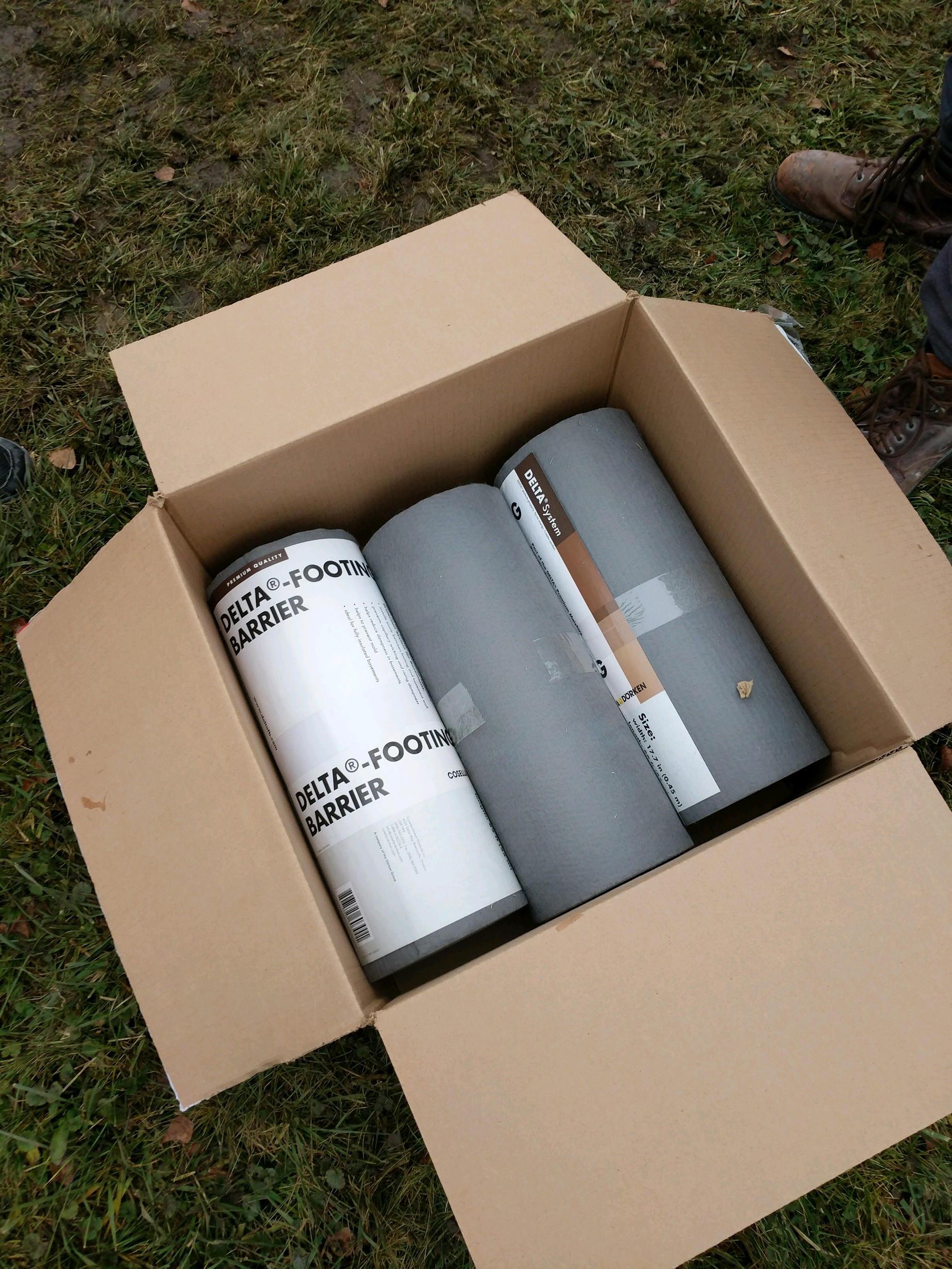
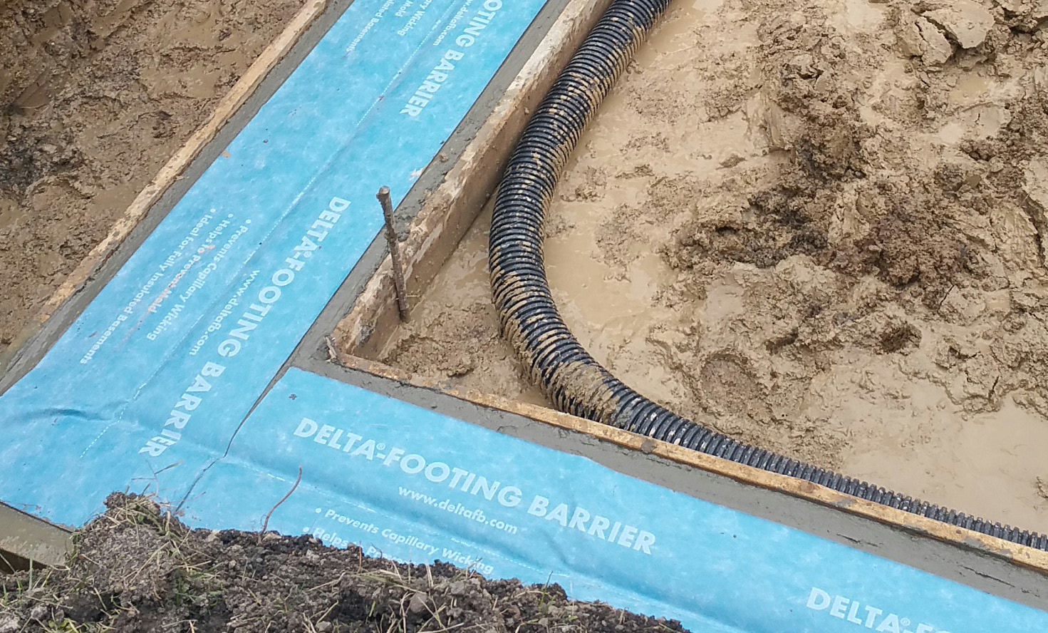
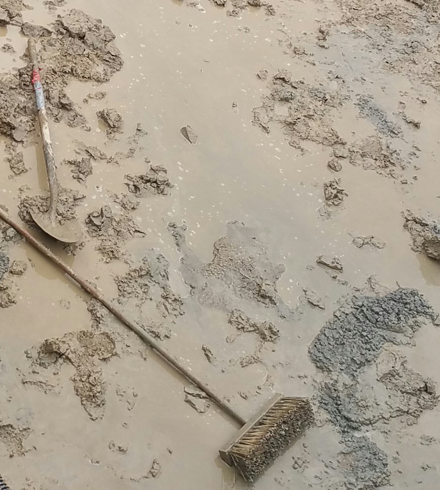
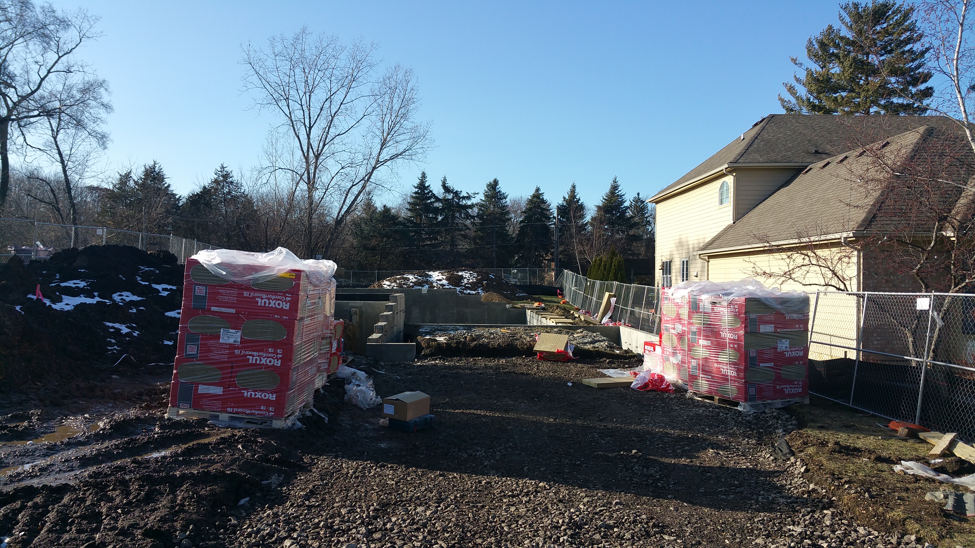
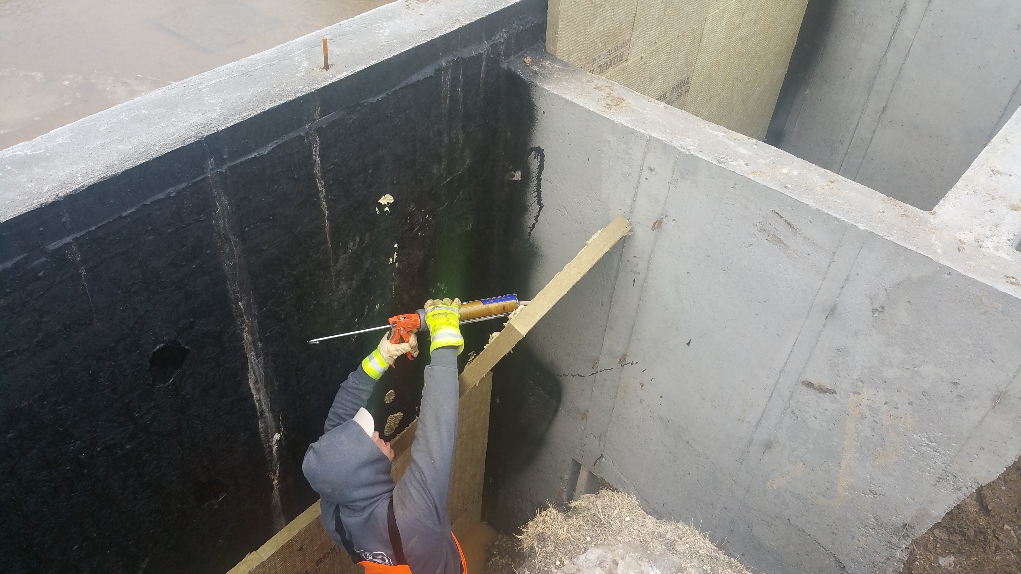
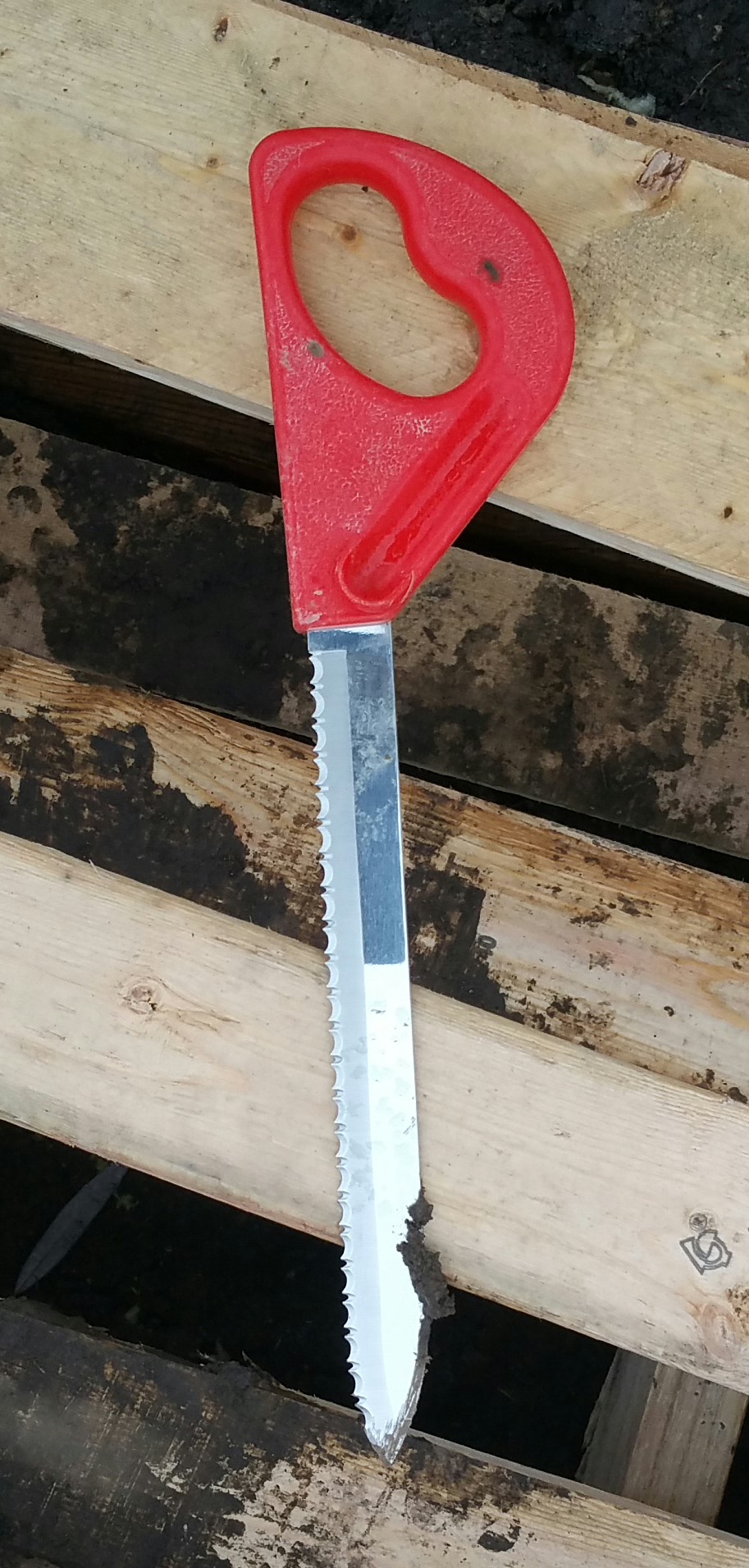
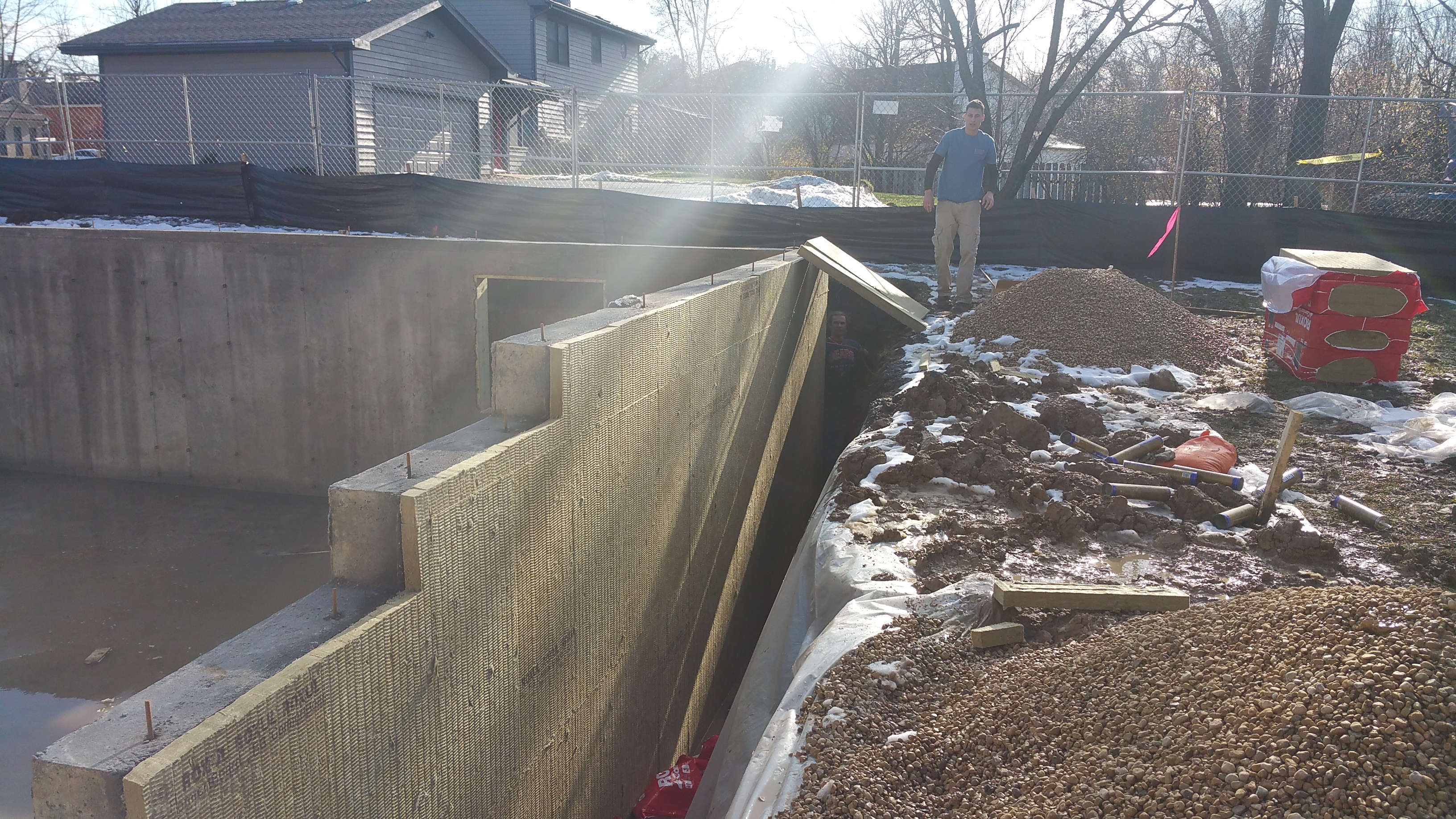
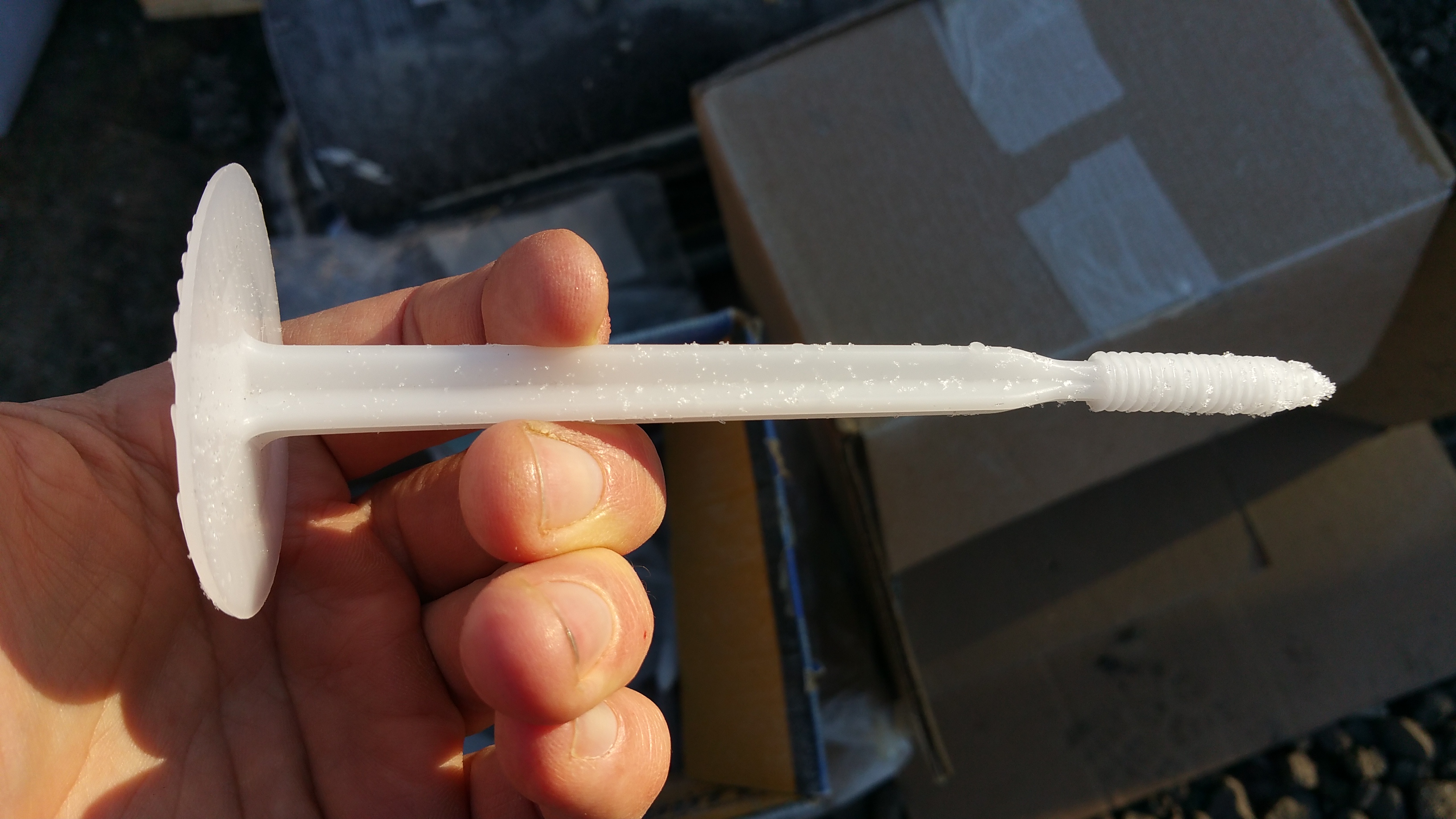
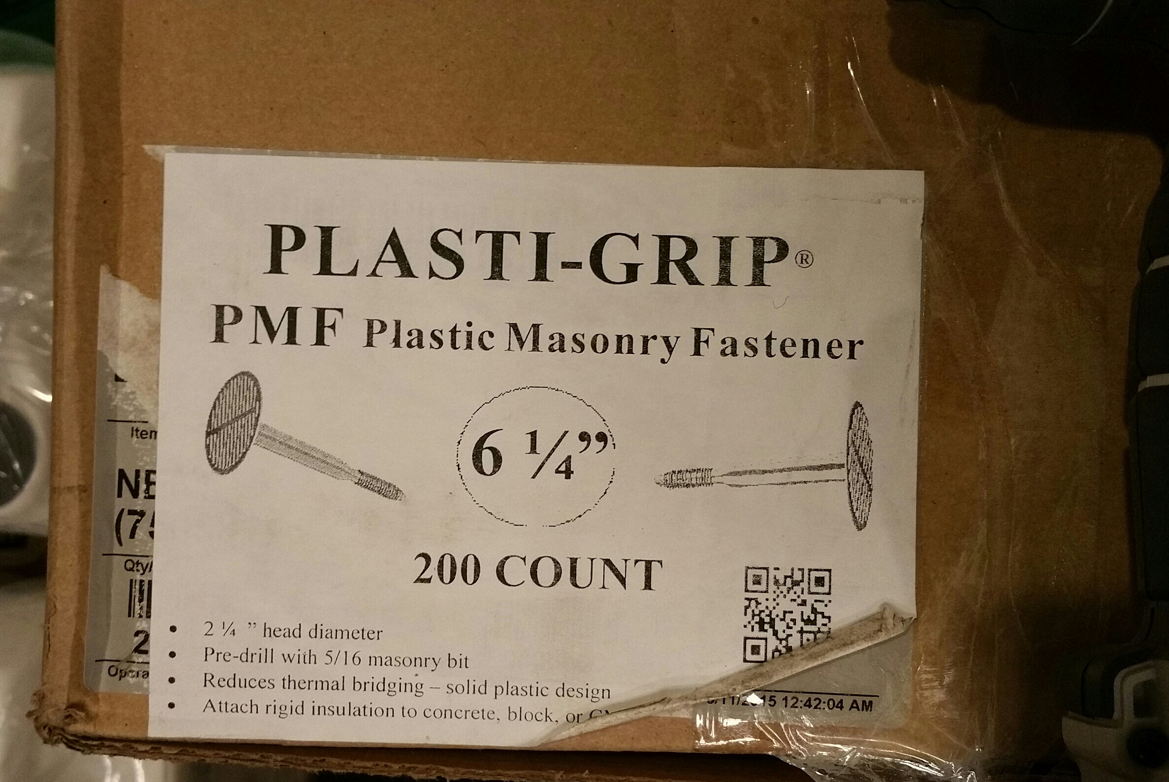
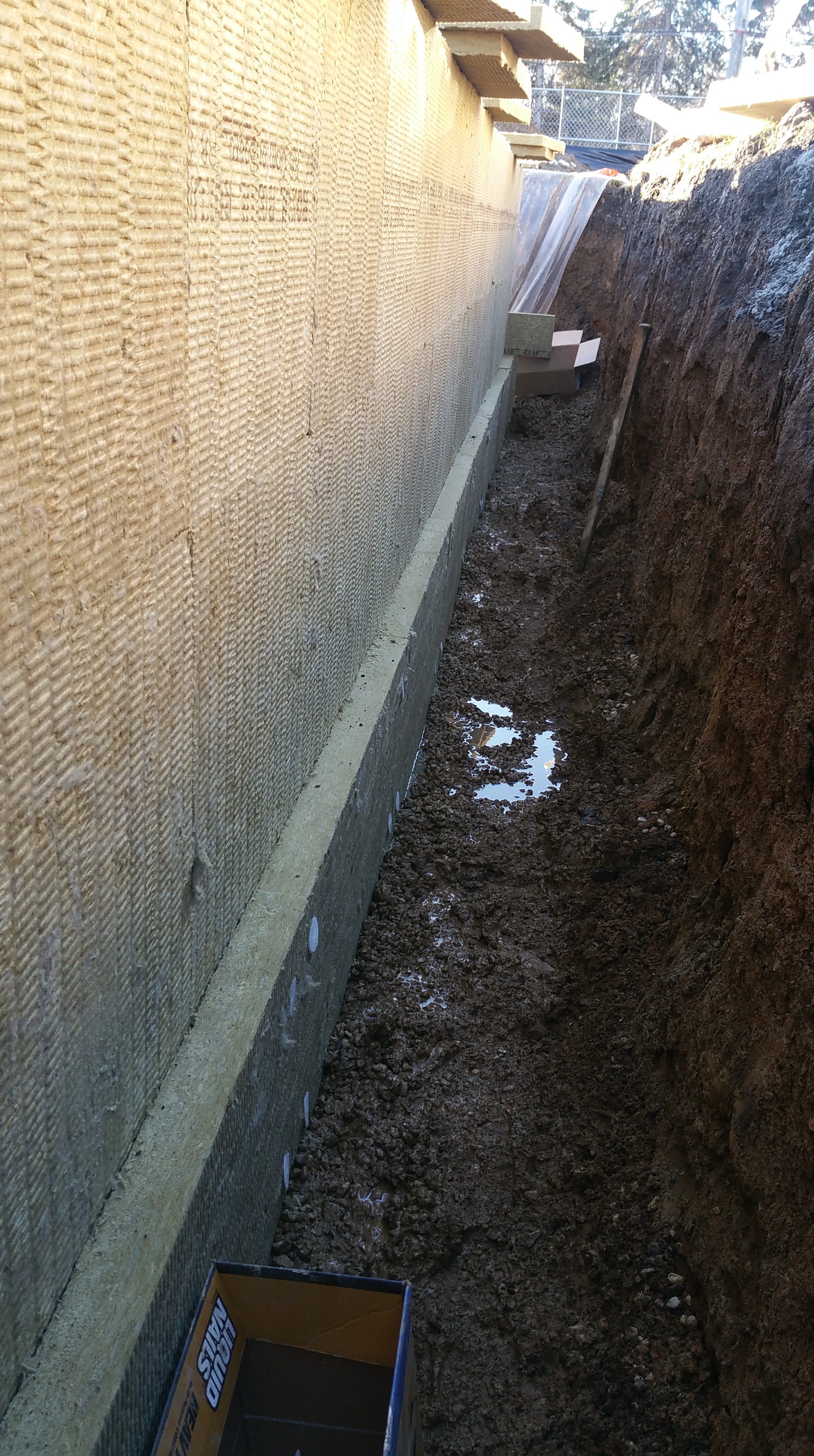
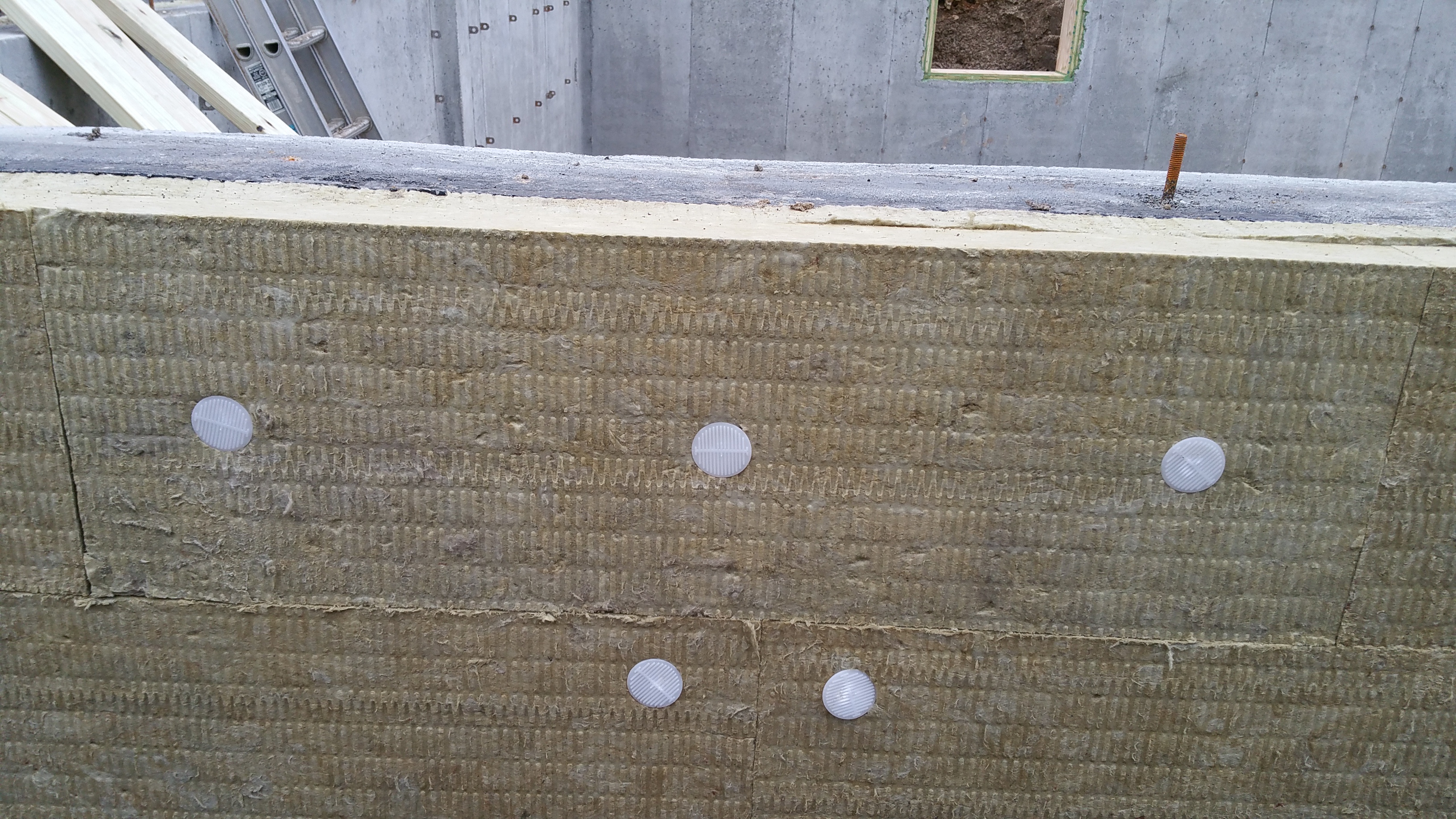

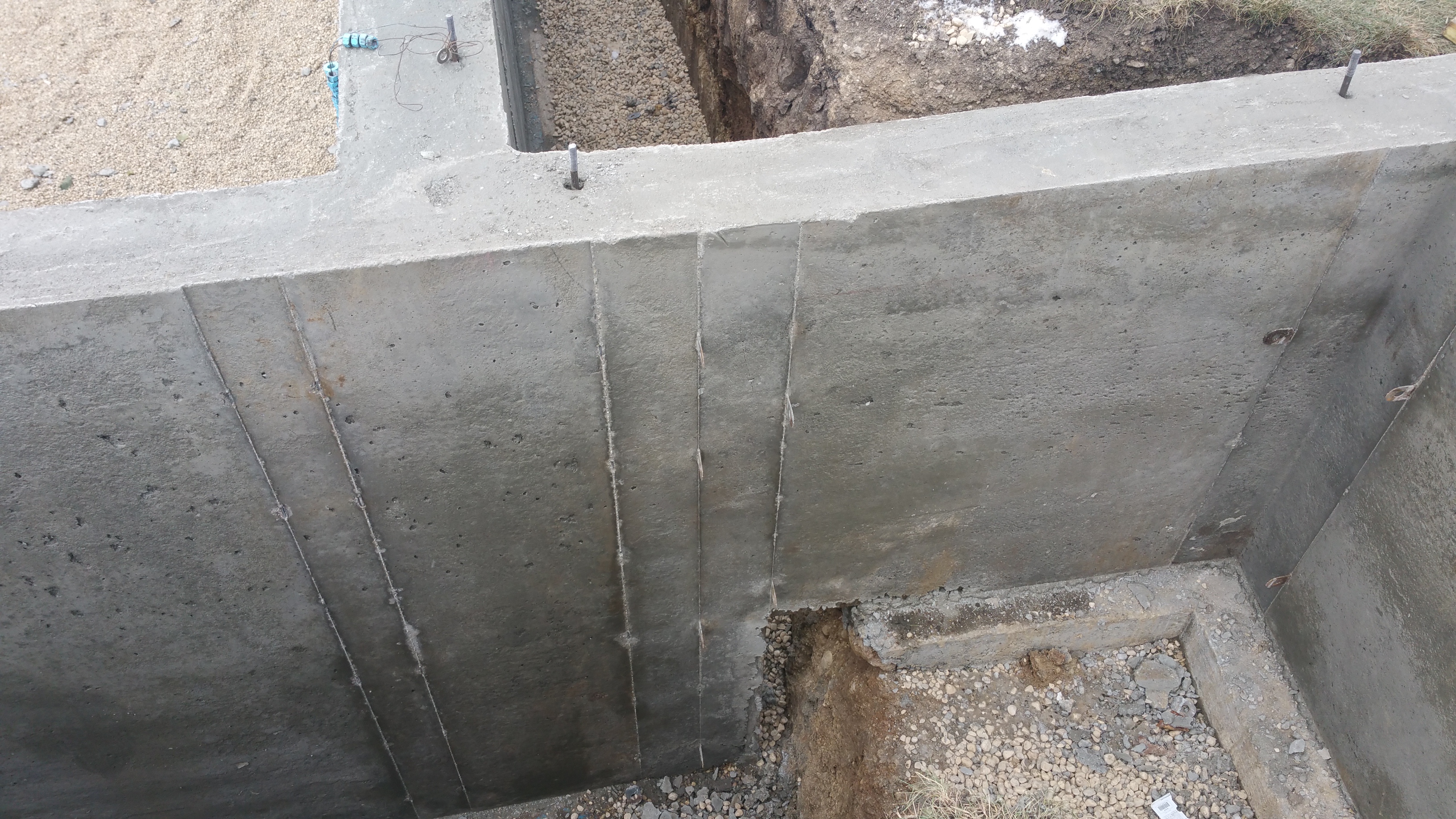
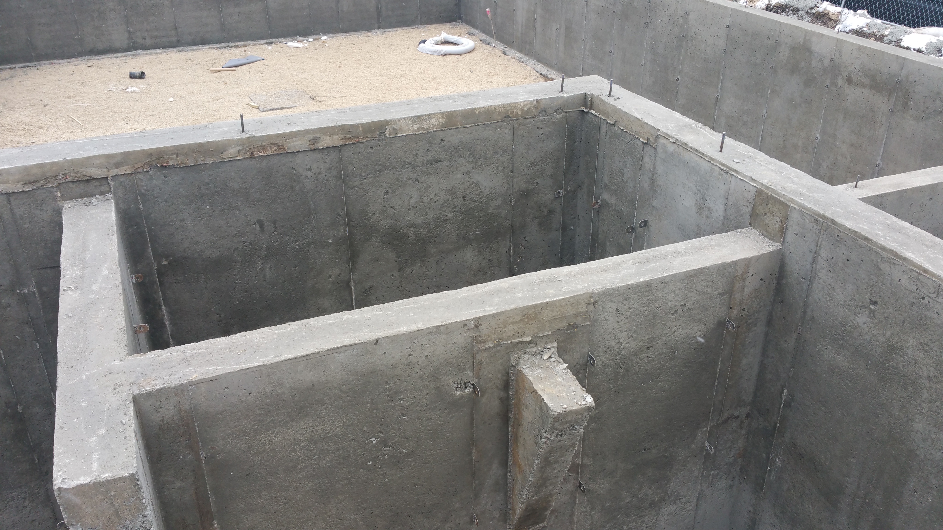
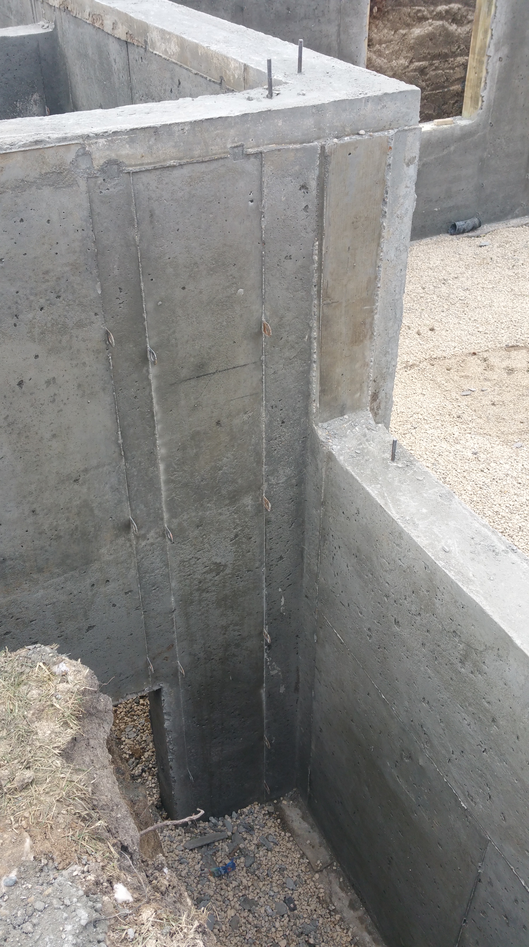
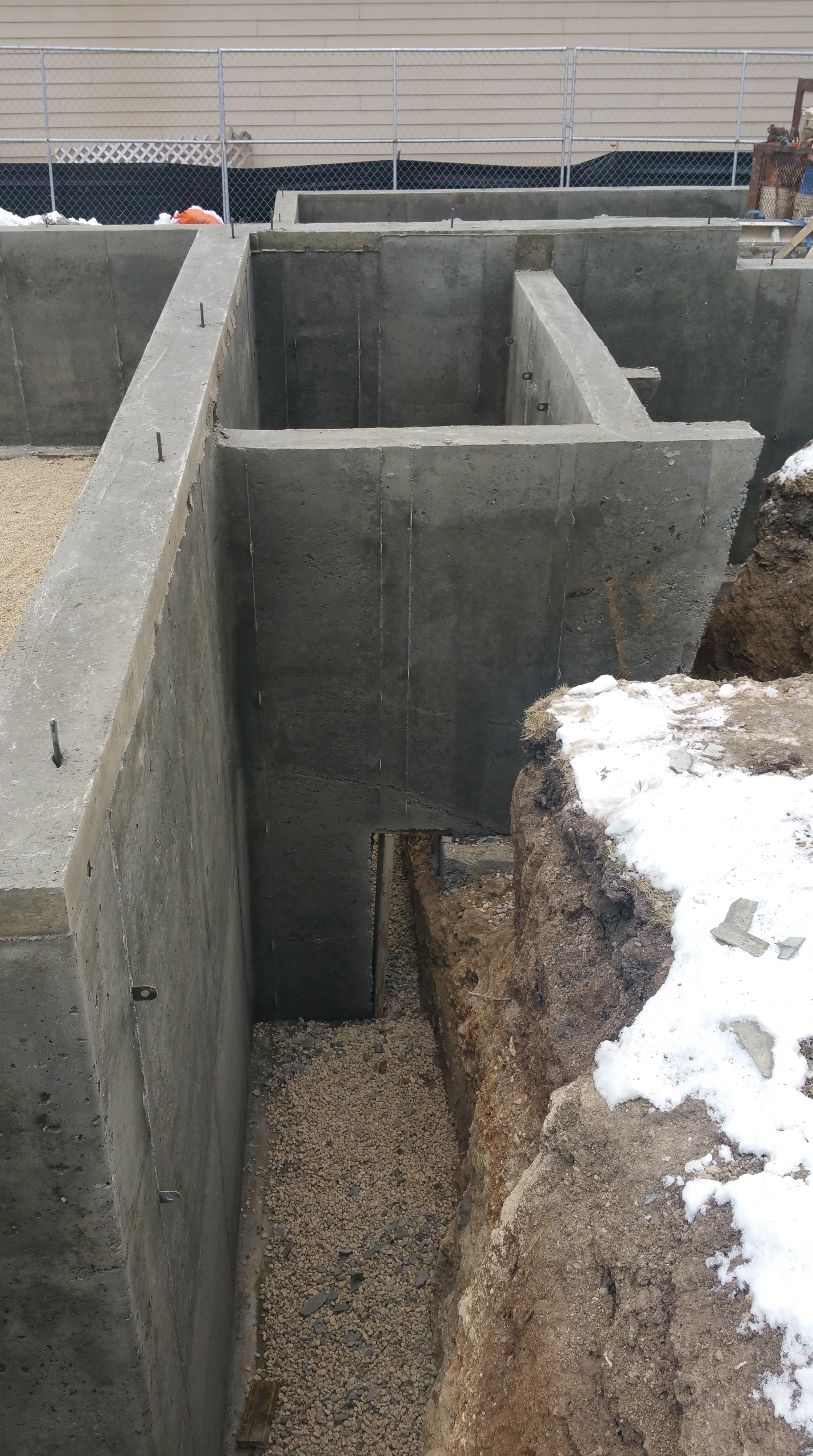
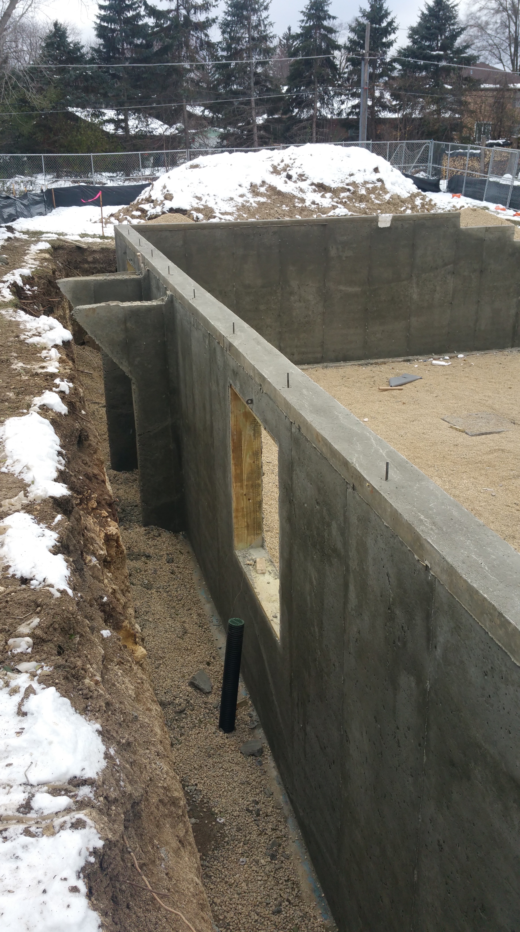
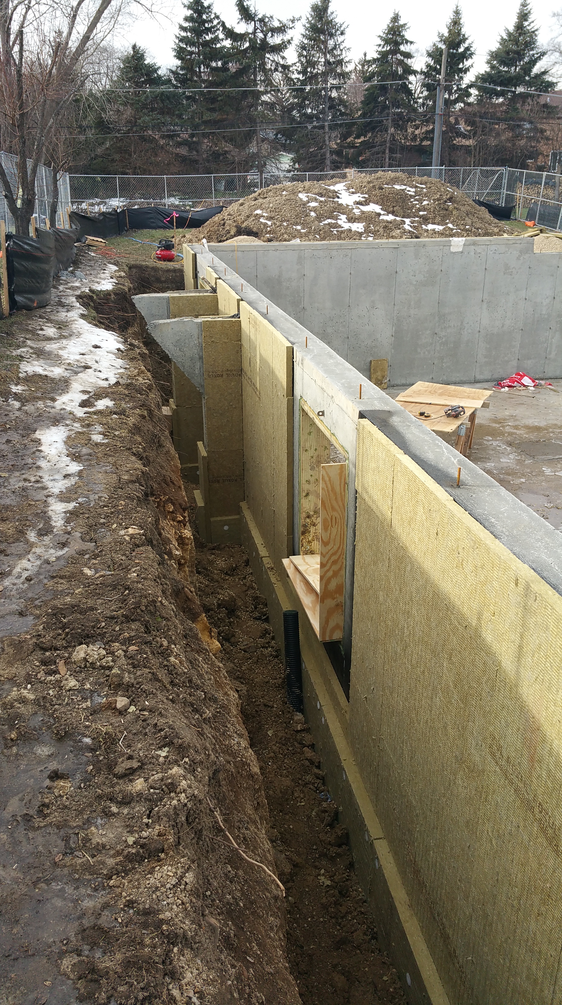
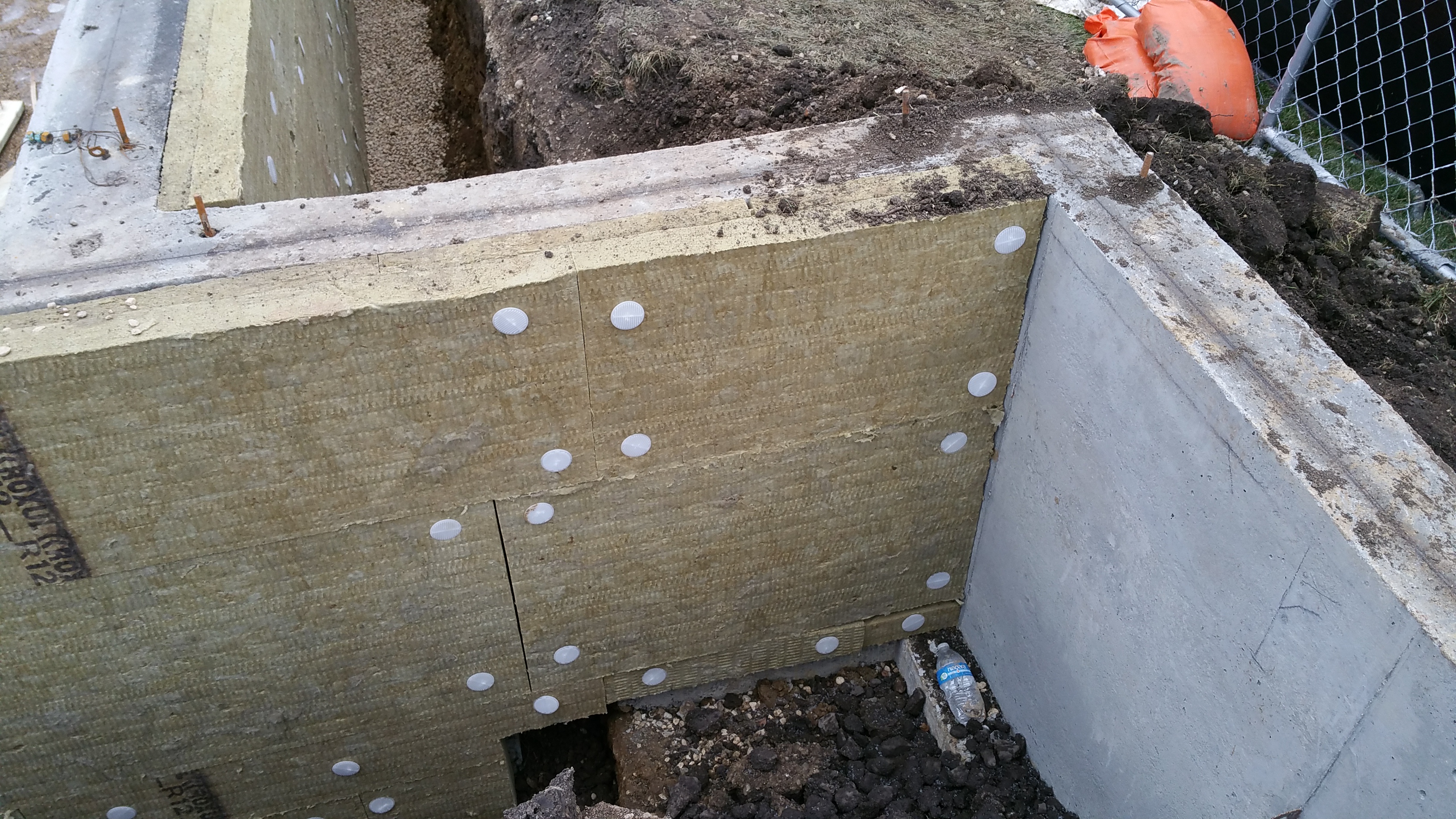
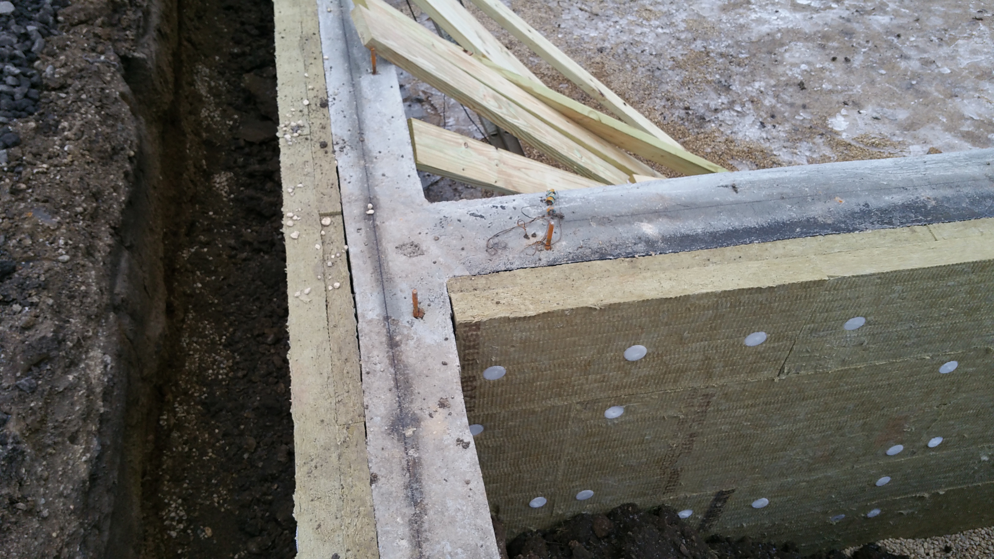
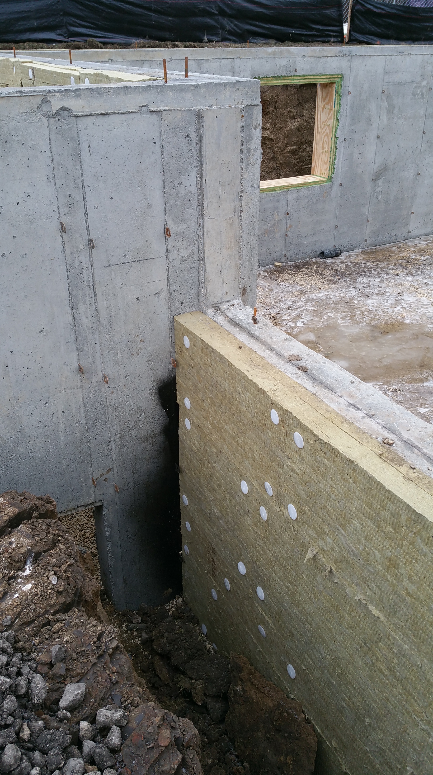

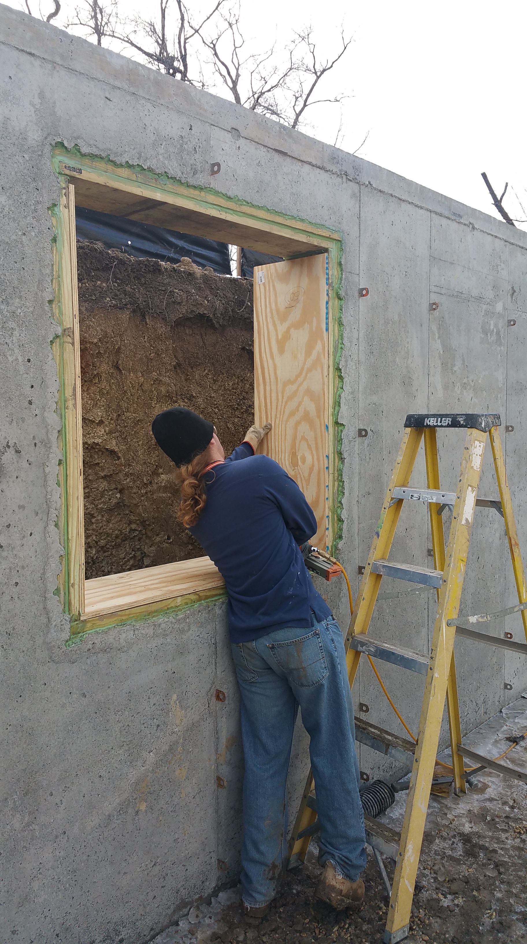
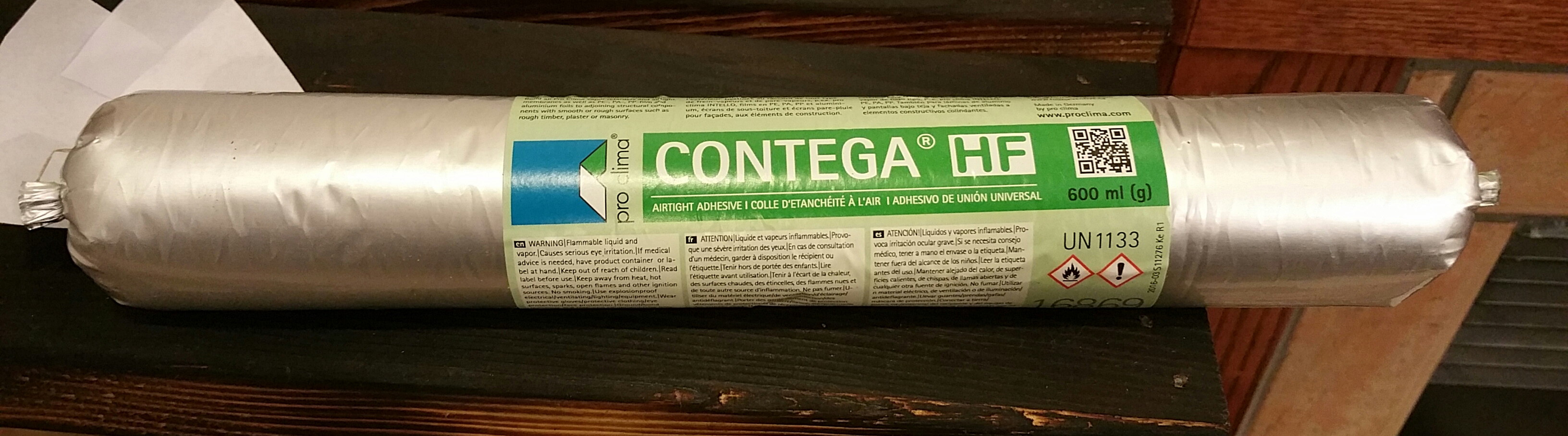
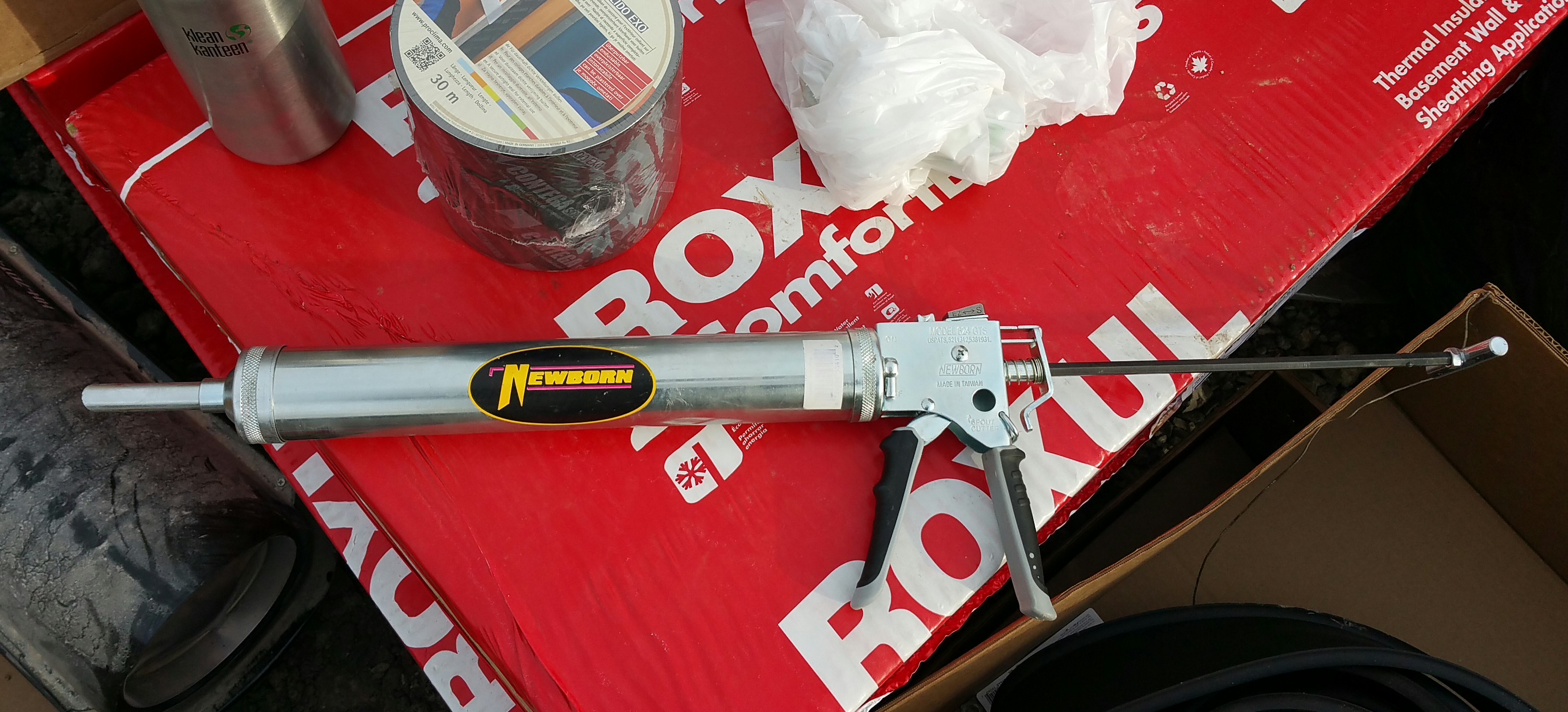
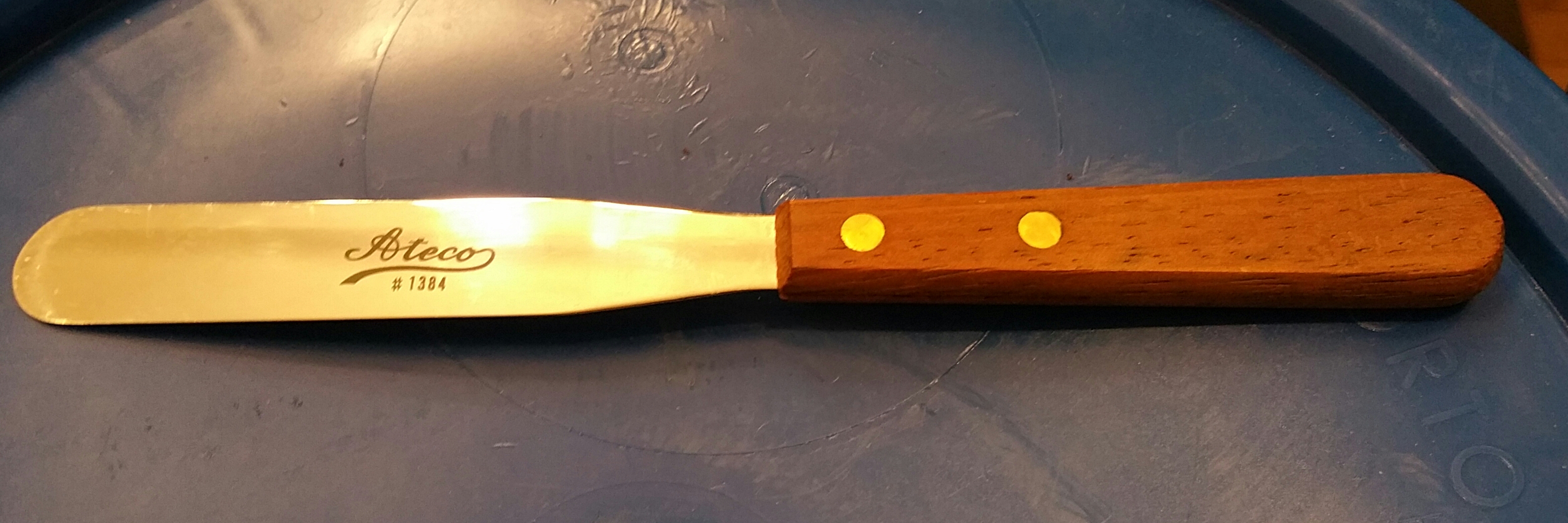

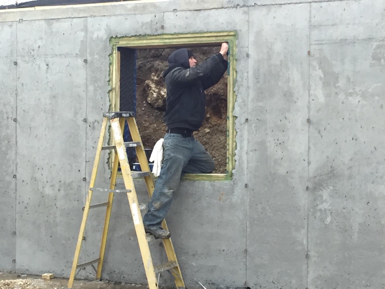
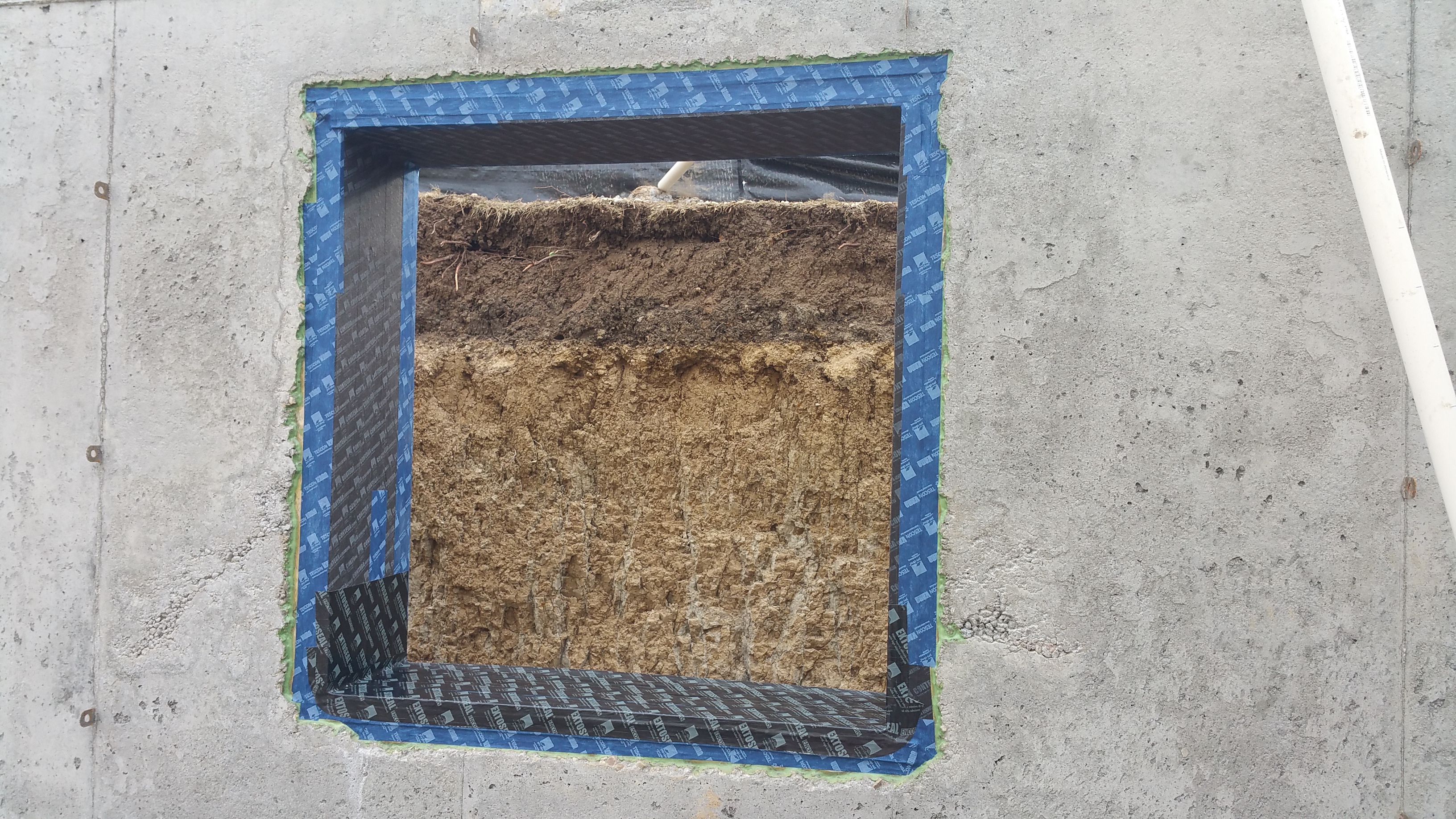

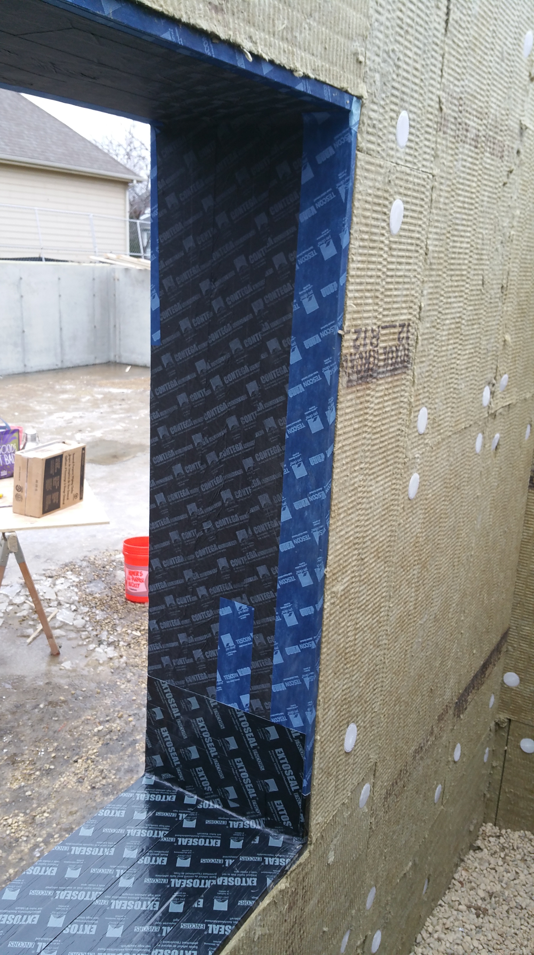
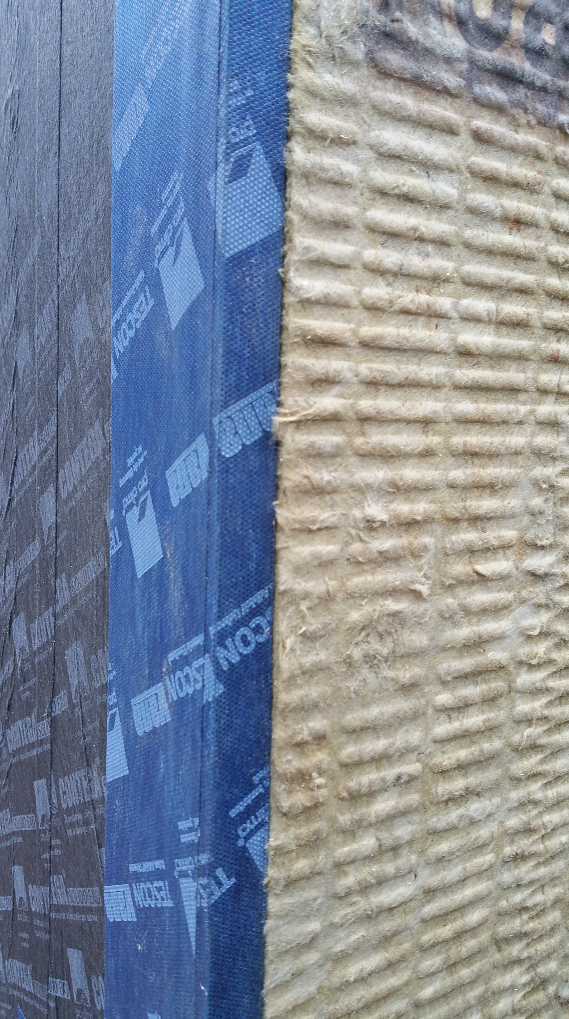
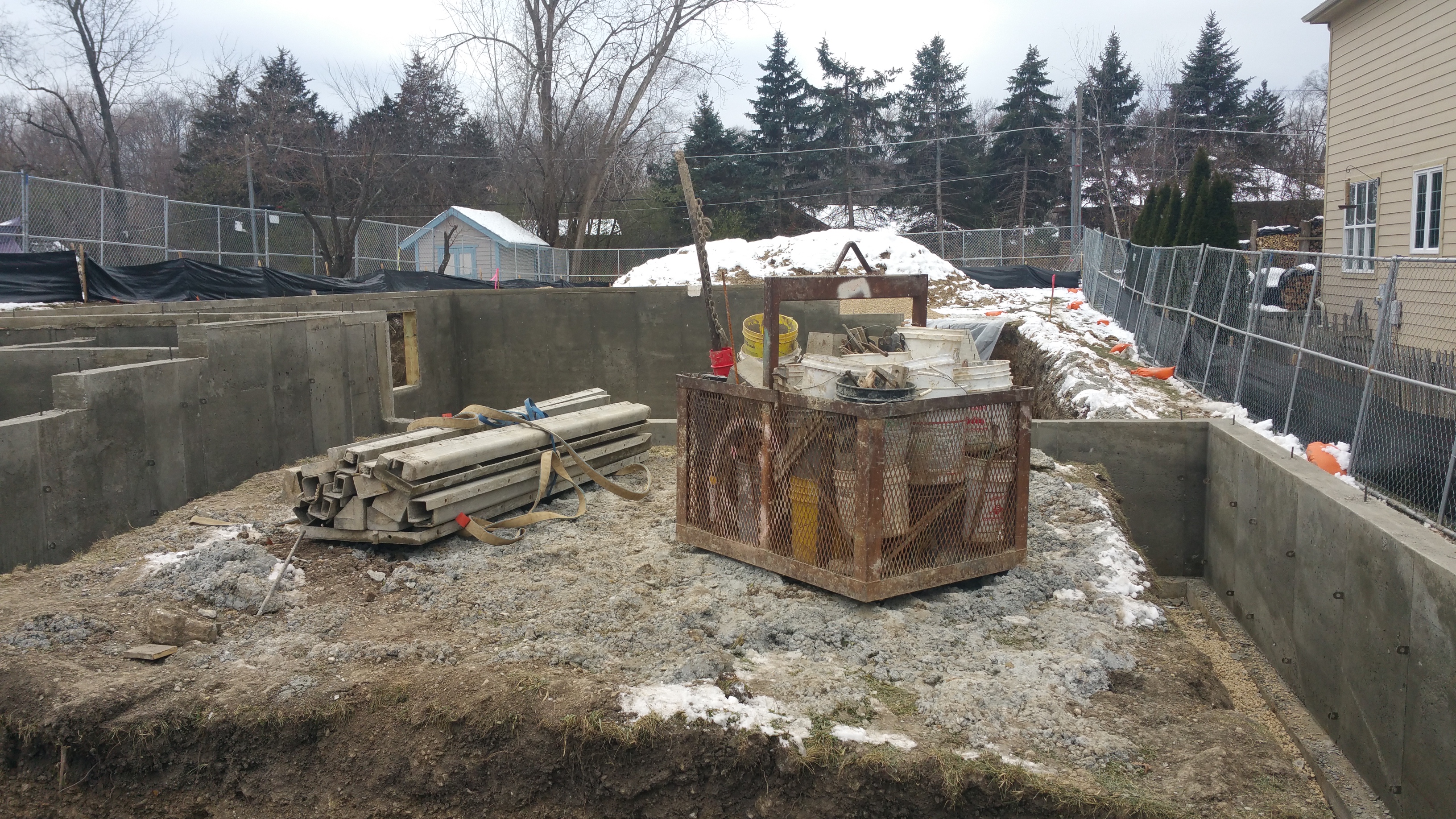


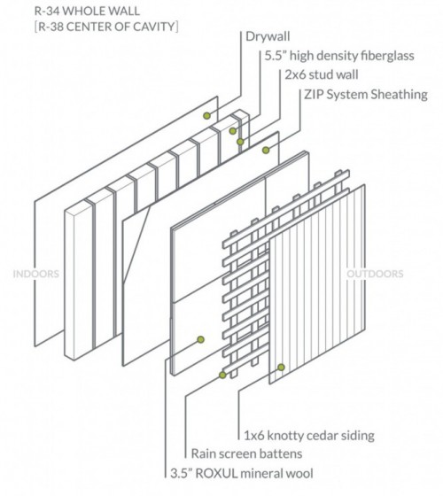
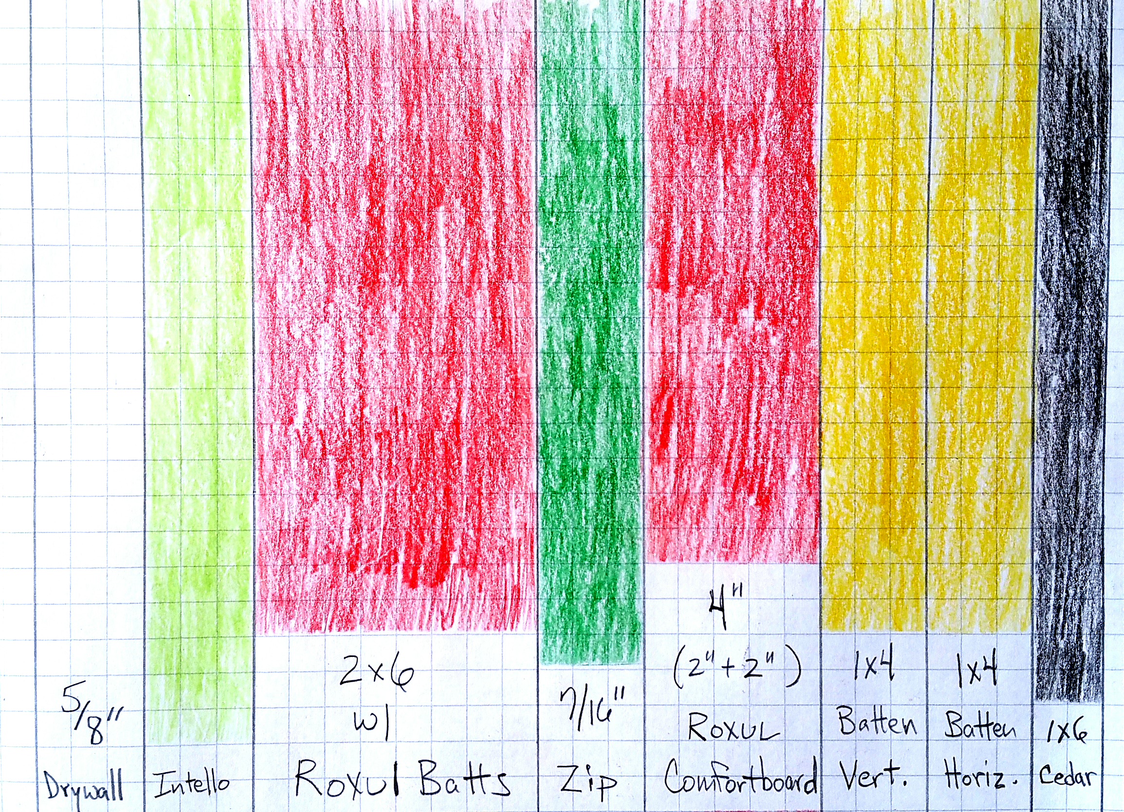


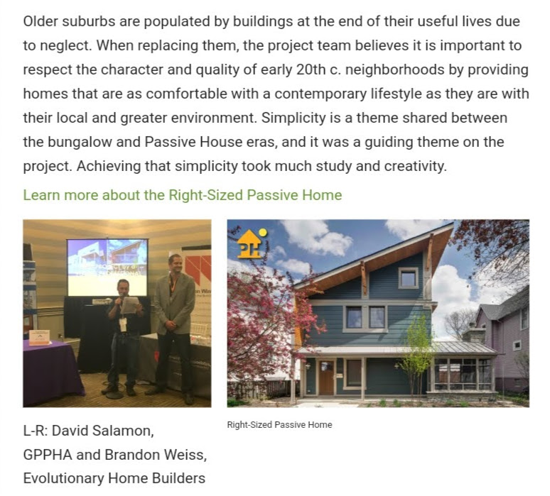


You must be logged in to post a comment.